
Neopixel Light Beam Clock
Print Profile(1)

Bill of Materials


Description
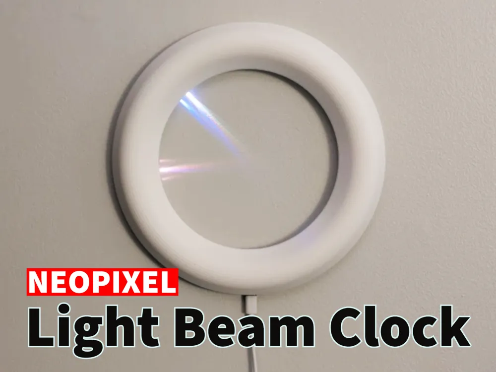

This minimalist clock uses light beams from an LED light strip to display the time on the wall, and is a personal adaptation inspired by a project found online. This clock connects to WiFi and sets the time automatically, casting the hour, minute, and seconds onto the wall in the center. The clock display is a WS2112B light strip (1m 96 IP30; $4.38), powered by a tiny ESP32C3 ($4.99), and is easy to build for anybody who is comfortable with basic soldering.
Boost Me (for free)
If you appreciate my work, please consider leaving a rating and a boost. If you don't like my work, boost someone else and don't let it go to waste! Constructive criticism is always welcome.
Assembly Instructions
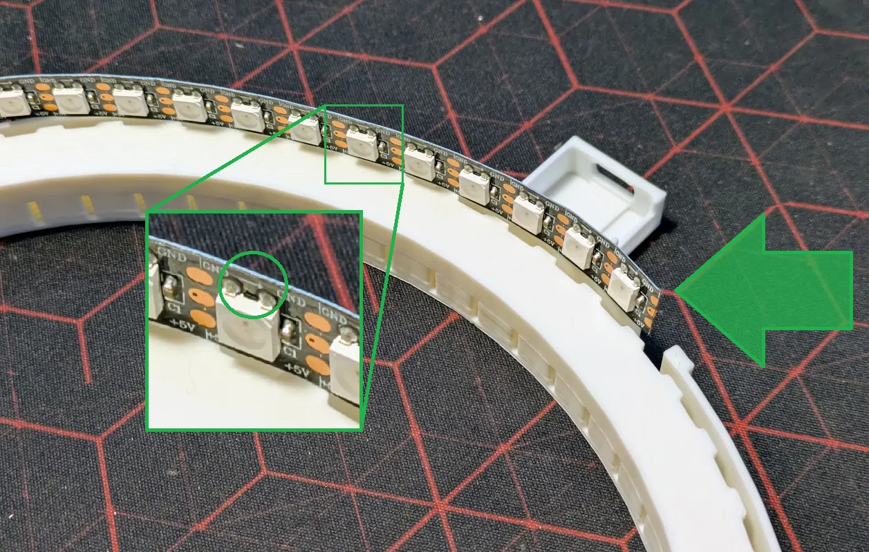
Important: Make sure you are using a strip that contains 96 LEDs per meter and without any silicone cover over the LEDs. In the link provided, this is indicated by the 1m 96 IP30 choice. You need exactly 60 LEDs, so carefully cut extra LEDs off the strip. (Take note of the arrows to make sure you cut the correct end.)

- While the parts are printing, grab the code and flash it to the ESP32C. (Don't forget to set your WiFi settings in wifi_credentials.h)
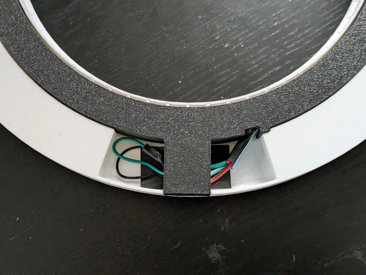
Carefully insert the LED strip into the inside part of the model. It is a firm fit, so be patient and gentle! The ends of the strip meet at the cutout as shown below. I find it easy to start with the last LED (green arrow) and work backwards around the circle. After the whole strip is lined up, gently start pushing the LEDs down.
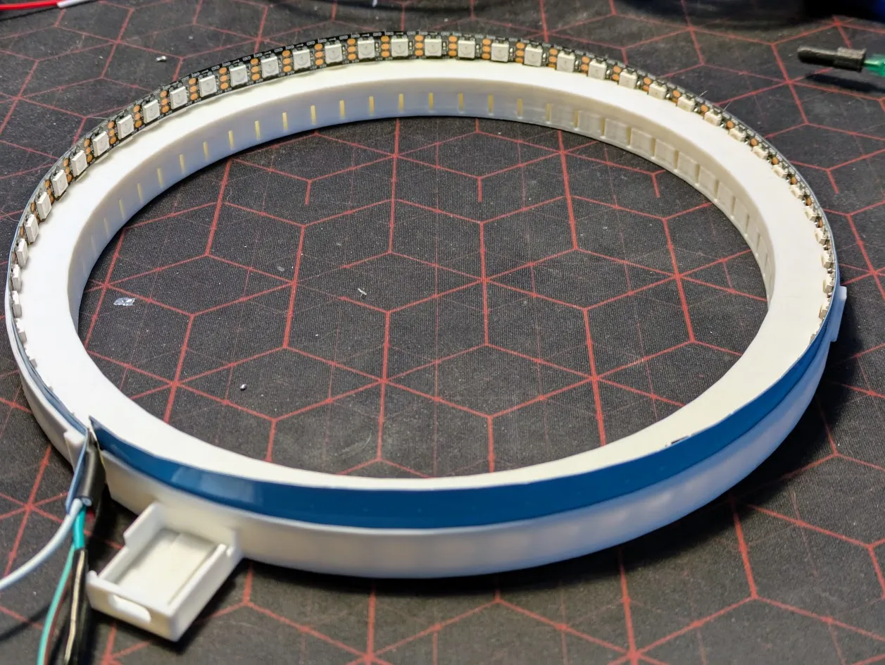
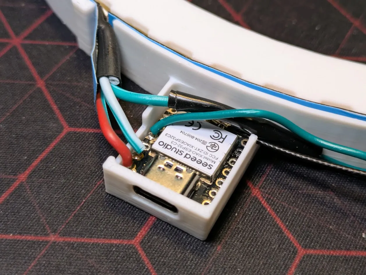
- Trim and connect the wires as follows:
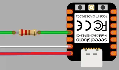
- Red (power): solder to ESP32C +5V
- White or Black (ground): solder to ESP32C ground
Green (signal): leaving a little extra to work with, solder a 330 ohm resistor and connect to GPIO 10. Wrap exposed wire.
- Remove other wires
Connect the WiFi antenna and push the ESP32C into place. It should fit somewhat firm, but if you want you can add some hot glue to hold it in place.
Turn the inside over and gently push it into the cover. Make sure the antenna and any extra wire are out of the way. The parts will fit together with a loose friction fit that hold them together but make it so you can take it apart without causing damage.
Hang it on the wall and plug it in!
Troubleshooting
Need help? Send me a DM or post a comment and I'll do my best to assist. A couple notes to start out:
- A WiFi connection is needed to set the time. Blue lights will show while it tries to connect and a red light will show if it times out.
- The code is AI-generated and is easy to customize or enhance.
License

You shall not share, sub-license, sell, rent, host, transfer, or distribute in any way the digital or 3D printed versions of this object, nor any other derivative work of this object in its digital or physical format (including - but not limited to - remixes of this object, and hosting on other digital platforms). The objects may not be used without permission in any way whatsoever in which you charge money, or collect fees.


Comment & Rating (25)