MX3.0 Connector Housing 4-Pin Custom Double-Ended Male-to-Male Reverse MX3.0 Cable 4p for BMCU Connection


Print Profile(1)

Description
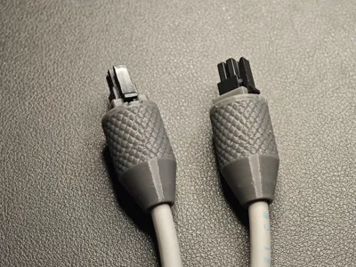
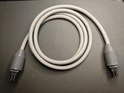
This print is a 4-pin MX3.0 connector housing, enabling the creation of a custom dual-headed, reverse-polarity MX3.0 BMCU cable. The finished product achieves a near-production aesthetic, allowing for custom wiring configurations for diverse applications. No screws are required for assembly. PETG filament is recommended; other parameters utilize default settings. Tree-like supports are necessary, facilitating easy removal. An organic tree support setting is suggested for optimal surface smoothness.
Cable Kit Materials: Two printed connector housings, 4-pin 0.3 sq mm wire (5.2 mm outer diameter), two MX3.0 male connector boots, and eight-pin terminal connectors. (Crimp the wires and insert the connectors into the boots before installation)
Tools: Wire crimping pliers are required. For those without crimping pliers, please consult this guide: 【How to crimp wire connectors without pliers - Bilibili】 https://b23.tv/bLDgCae
Compatibility is limited to wires with an outer diameter of approximately 5.2 mm. Thicker wires may prevent insertion or result in excessively tight clamping, while thinner wires may not be adequately secured. Some slightly thicker wires may be accommodated but require hole expansion through sanding.
Terminal crimping illustrated below

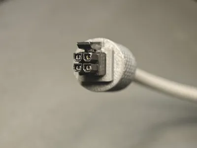
BMCU wiring diagram shown below. Identical wiring order for both ends. (Ensure correct 24V connections, and observe the insertion direction (refer to the image for the port orientation, noting the difference in rounded and square corners))


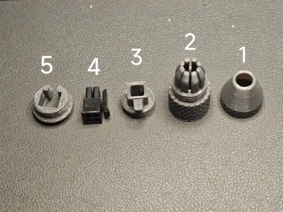
Installation sequence illustrated below (Note the orientation), (Crimp the wires and insert the connectors into the boots before installation)

License
You shall not share, sub-license, sell, rent, host, transfer, or distribute in any way the digital or 3D printed versions of this object, nor any other derivative work of this object in its digital or physical format (including - but not limited to - remixes of this object, and hosting on other digital platforms). The objects may not be used without permission in any way whatsoever in which you charge money, or collect fees.
Comment & Rating (4)