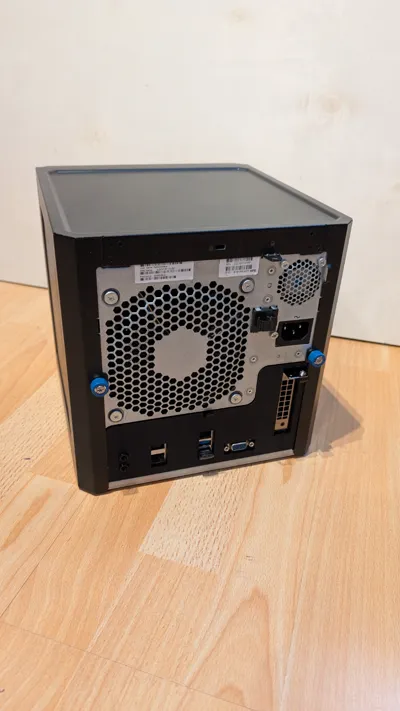
HP Microserver Gen8 mITX and MJ11-EC1 upgrade


Print Profile(2)


Bill of Materials


Description
Upgrade Tray for MiniTIX.
→ please make shure to se a low profile cooler
Upgrade Tray for the Gigabyte MJ11-EC1 ITX Board.
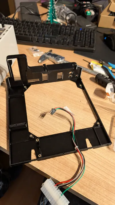
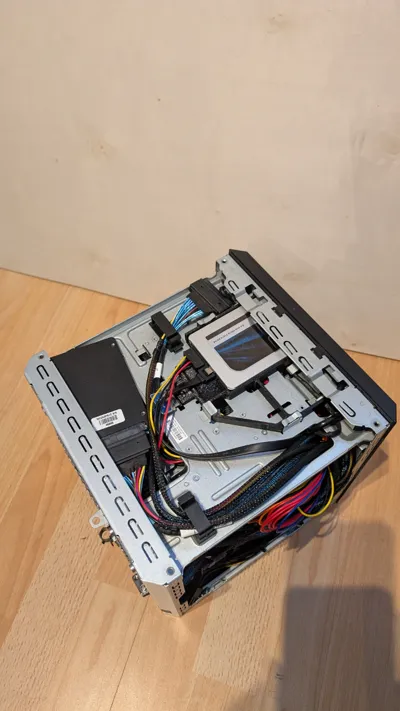
I have designed a complete solution to replace the old Motherboard Tray.
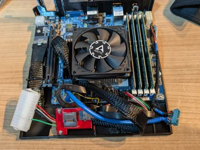
In my configuration i am using a Tesla P4, Sata SSD and U.2 SSD.
You will need the following Parts:
- Motherboard: Gigabyte MJ11-EC1 + RAM
- power supply: Inter-Tech Argus FA-250
- 80mm x 15mm Fan
- 120mm x 25mm Fan to replace original HP Fan
- SlimSAS4i to SFF-8087 adapter https://www.amazon.de/dp/B09W5CX6DM?ref=ppx_yo2ov_dt_b_fed_asin_title&th=1
- SlimSAS4i M2 Adapter https://www.amazon.de/dp/B09DGFG81F?ref=ppx_yo2ov_dt_b_fed_asin_title&th=1
- SlimSAS4i to PCIe x4 Adapter https://c-payne.com/products/slimsas-pcie-gen4-device-adapter-x4
- 2x Slim SAS4i cable https://www.amazon.de/dp/B0BYCWVJDK?ref=ppx_yo2ov_dt_b_fed_asin_title&th=1
- 1x SlimSAS8i to 2x U2 Cable (optional for U.2 SSD) https://www.amazon.de/dp/B0DN1BG7YQ?ref=ppx_yo2ov_dt_b_fed_asin_title
For more information you can read my posts on Hardwareluxx (german): https://www.hardwareluxx.de/community/threads/hp-microserver-gen8-mainboard-upgrade.1364026/
Assembling:
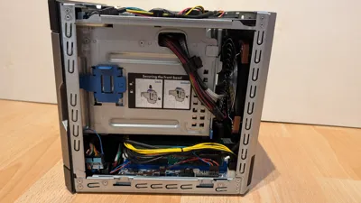
insert the brass insert in to the holes for the motherboard, the studs vor the SFF8087 adaptor and the sliding clips for PCIex4 adapter and slide in the PCIex4 adapter holders. Also install the treaded inserts in the Fan Adapter


Screw the chassis clip with the self taping screw on the Tray

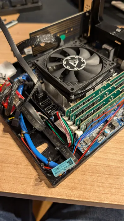
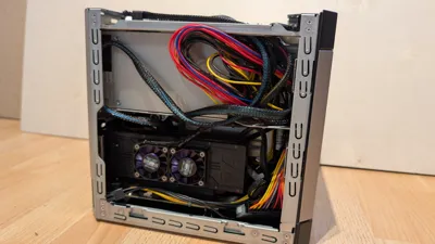
- Unscrew Original Fan. Screw the new Fan adapter with the M3x6 Screws on the studs. Then install the new Fan with the M3x8 Screws on the adapter
Install the PCIex4 Adapter, Motherboard and SFF8087 adapter board on the Tray using M3 Screws for computers. Also install the M2 to SLimSAS4i Adapter in the M2 Slot of the Motherboard.
Dont forget to stick in the reset button before installing the Motherboard.

You can install the powerbutton simply by stick it onto the power button of the MJ11-EC1
- Wire up your Adapter Boards and fix it with zip-ties.
(Optional) you can use a 3mm LED to use the front led bar as a power led. I have used a fan connector for the power LED.
You will need a 470Ohm resistor for using a fan connector or a 15 Ohm resistor for using the front IO pins on the mainboard.


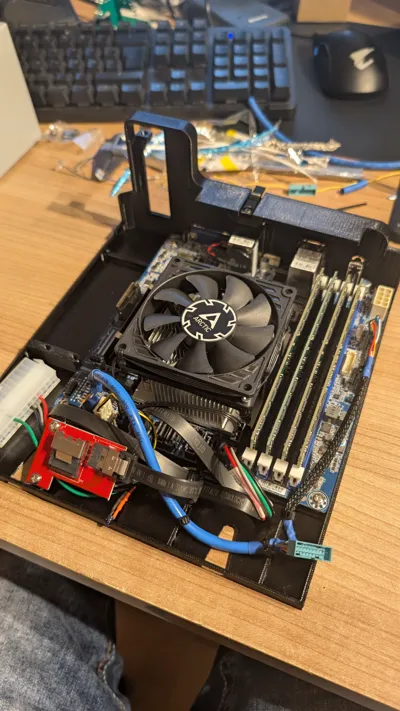
- Depending on your configuration yo can install an PCIe Card and slide in the Tray.
- When it is halfway in you can connect the remaining connectors. 8PIN ATX power, 24pin ATX, SFF8087, SATA, PCIe 6PIN für PCIe Adapter
- Slide in completely
Allshould be done. Time for power up your maschine
License
You shall not share, sub-license, sell, rent, host, transfer, or distribute in any way the digital or 3D printed versions of this object, nor any other derivative work of this object in its digital or physical format (including - but not limited to - remixes of this object, and hosting on other digital platforms). The objects may not be used without permission in any way whatsoever in which you charge money, or collect fees.
Comment & Rating (12)