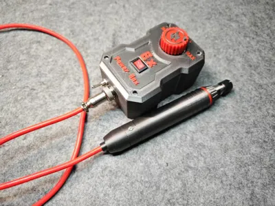
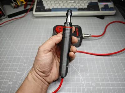
Miniature Brushless Electric Grinding Pen


Print Profile(2)

Description
For detailed installation instructions, please refer to the installation video
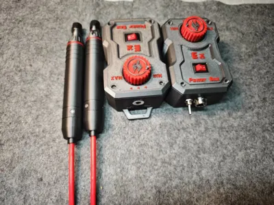
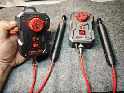
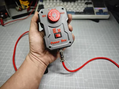
April 13th update: Added a detachable pen tail cap, compatible with GX12 female header. A new dinosaur head icon rotary cap has also been added

Connectors:Drive box screws: M2*14 self-tapping screws, pen tail fixing screws: M2*6 self-tapping screws. Motor fixing screws: M1.6*6 screws. Drive board fixing screws: M3*6 self-tapping screws
Parts List (Purchase screenshots are included in the assembly guide for reference):
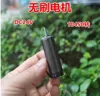
Small Brushless Motor (refer to the image)
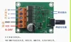
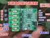
75W Brushless Motor Driver Board (Both green and orange versions are usable; the mounting screw positions differ, so select the drive box print that matches your chosen screws)
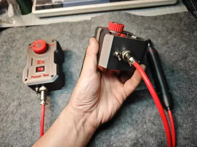
DC5521 High-Current Metal Female Header (power input)
Miniature Push Button Switch (forward/reverse switching)
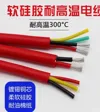
3-pin 0.3mm Soft Silicone Wire
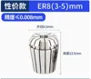
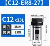
ER8 Drill Chuck
ER8 Collet 3MM (Choose according to your preferred grinding head; I use 3MM shank heads most often, so I purchased a 3MM collet)
KCD11 Rocker Switch (power switch)
GX12 3-pin Aviation Female Connector (connects the electric grinder pen and the drive box)
10K Potentiometer (three-pin) to replace the original circuit potentiometer
Installing the orange driver board requires removing the potentiometer. Forward/reverse switching can be achieved by connecting the two solder points next to the potentiometer to the two wires of the push-button switch
If using the green driver board, the potentiometer does not need to be removed. There are three solder points (5V, 0-5V, GND) where an external potentiometer can be connected for forward/reverse control, but the internal potentiometer needs to be set to maximum for the external one to function correctly. To save space, I removed the potentiometer in my own build. For the green driver board, forward/reverse switching is achieved by connecting a push-button switch to the CW/CCW solder points, with the other switch wire connected to the main ground.


Documentation (10)


License
You shall not share, sub-license, sell, rent, host, transfer, or distribute in any way the digital or 3D printed versions of this object, nor any other derivative work of this object in its digital or physical format (including - but not limited to - remixes of this object, and hosting on other digital platforms). The objects may not be used without permission in any way whatsoever in which you charge money, or collect fees.
Comment & Rating (0)