
Electron Microscope—Ultra-Low-Cost Electron Focusing Version v1
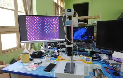
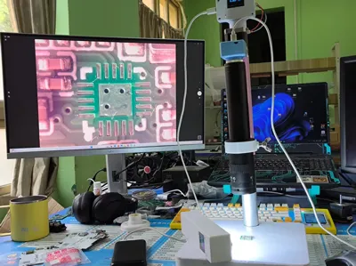
Print Profile(1)

Description
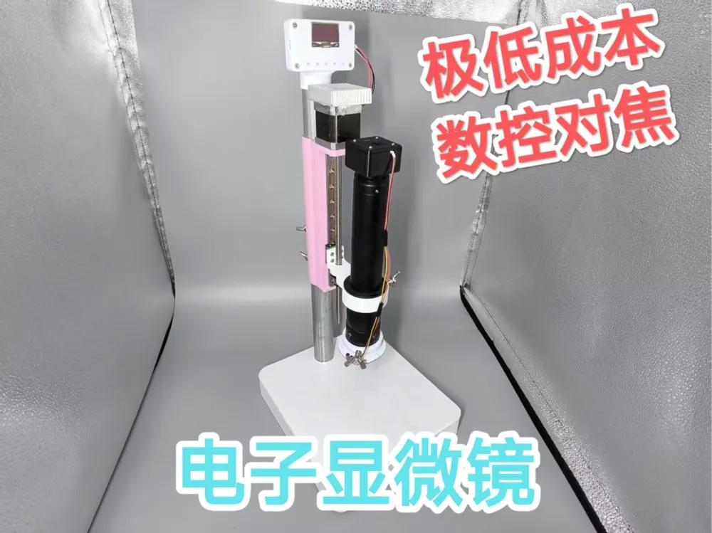
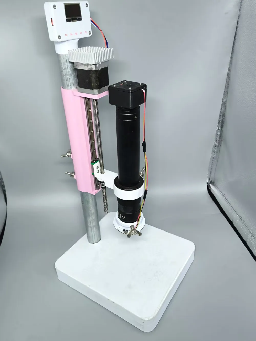
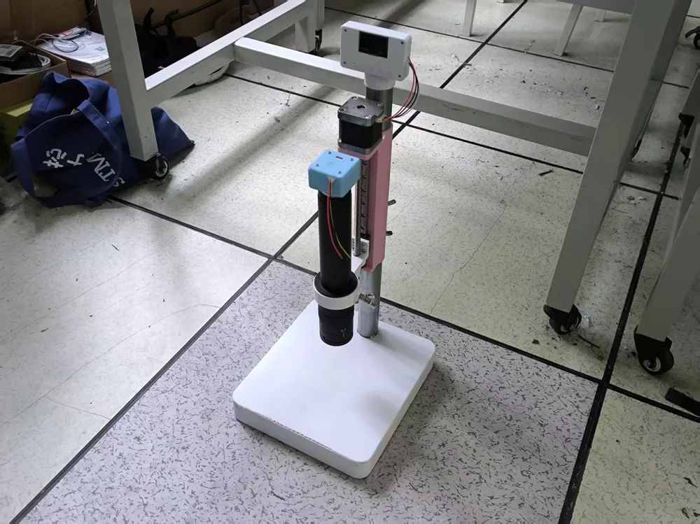
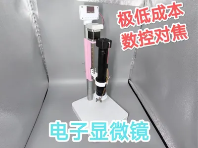
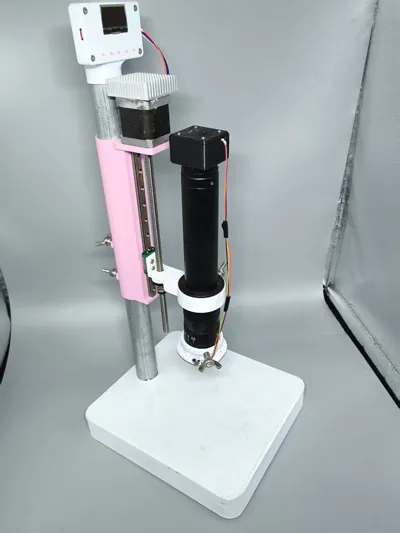
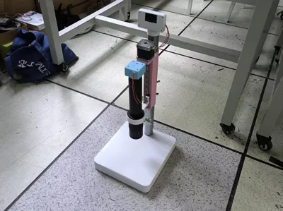
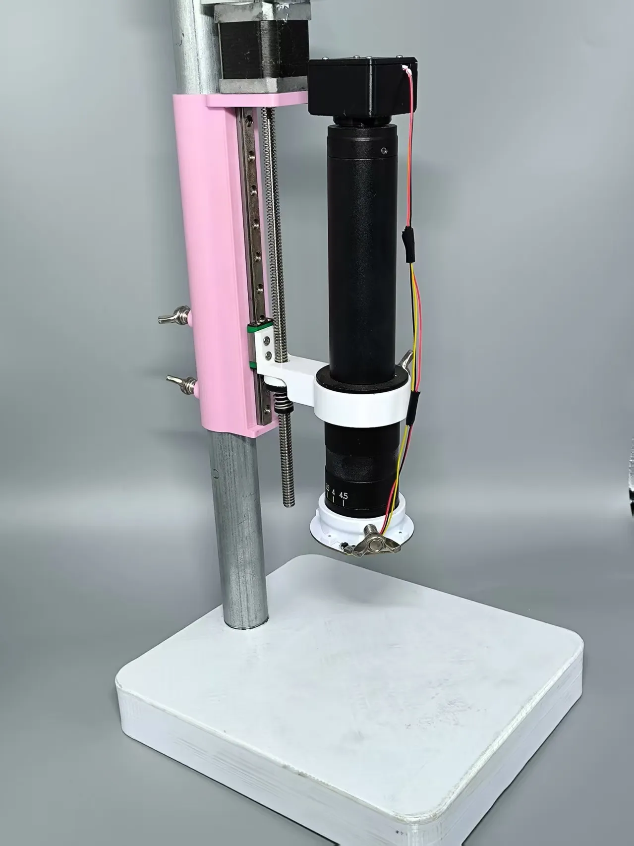
This is an electronic microscope, that's right, it eliminates the manual focusing of traditional electronic microscopes, replacing it with an extremely advanced stepper motor control that can increase lens movement accuracy to 0.001mm, while maintaining very low costs with a fully 3D Printed structural design, common hardware, and no expensive CNC parts.
Due to base size limitations, A1 mini cannot print this, but other models can
Key features:
- Total weight 3.9kg, not easy to tip over
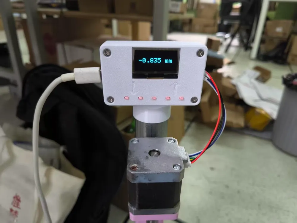
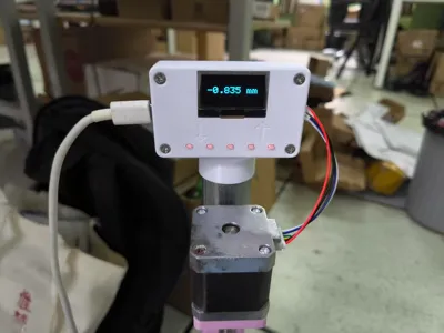
- Electrically controlled travel 20mm, accuracy 0.001mm
- Lens (replaceable) 0745 1x eyepiece 0.7-4.5x continuous zoom objective
- CMOS (replaceable) IMX298 1/2.8-inch 16MP
- Type-C PD 20V input (motor)
- Type-C USB input (camera/light)
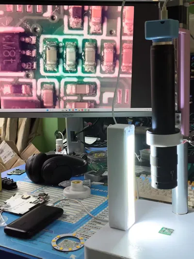
- Touchless dimming LED
All mechanical parts are low-cost off-the-shelf components, requiring only 1kg of PETG filament, with approximate costs as follows:
Mechanical structure (including filament) 50.2¥
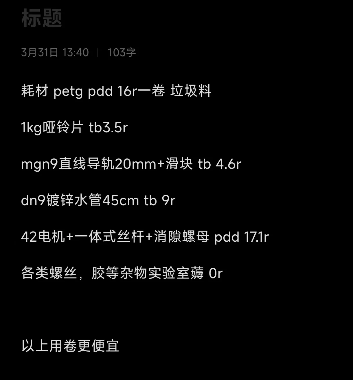
0745 0.7x-4.5x continuous zoom lens 75¥
USB camera board (IMX298 16 megapixel) 180¥
Electronic control (2*PCBA + manual soldering) approximately 30¥
Does not include screws, copper pillars, thermal adhesive, and other small items
Additional notes on cost:
The items listed are not absolute models, especially the lens and CMOS board, which can be replaced by yourself. These are the main cost drivers and directly determine the final imaging and shooting effects
This project is not sponsored in any way, all materials were purchased by me, and there is no intentional inflation of material costs
If you still find it unreasonable after reading, it is recommended to directly buy the so-called "10 million 1600x magnification with screen" for 130 with free shipping from pdd and close this page, fitting the stereotype
-----
New product preview: Upcoming release v2 high-performance microscope, equipped with a 1-inch large sensor CMOS + VESA screen mount, it is recommended to use a 4k screen for best results, expect higher costs (electronic materials >1k, requires BGA mounting/reballing capability)
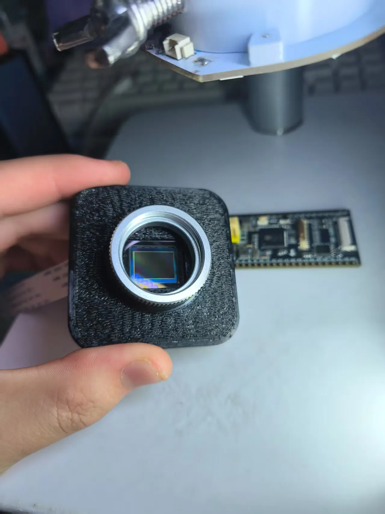
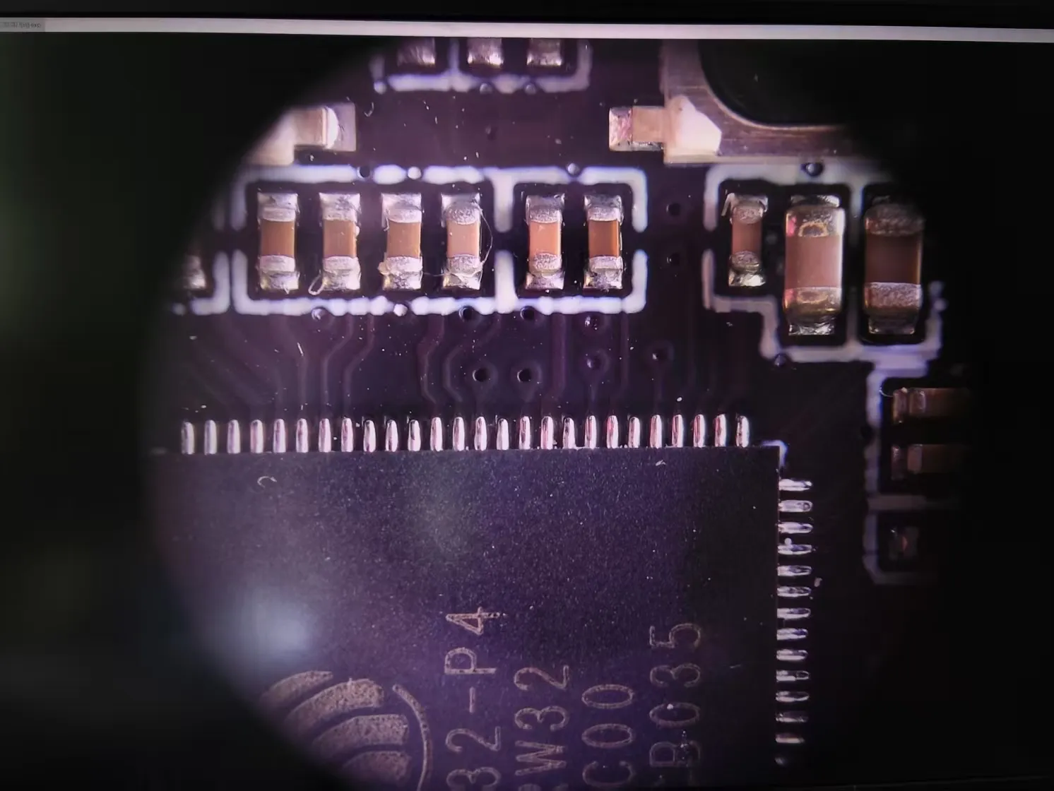
(too lazy to screenshot, screen manually photographed, 4k30)
Also, V2 lite is in preparation, 1/1.8-inch CMOS, lower-cost solution (4-500¥), currently being tuned
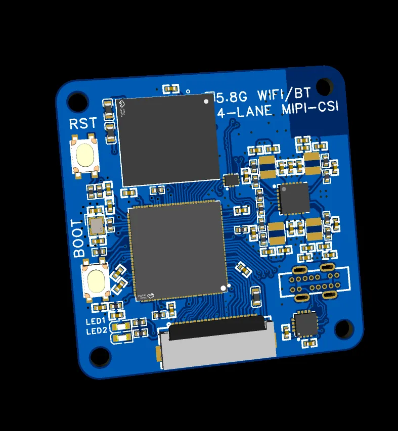
V2 lite CMOS+ISP motherboard
------
Schematic/PCB/Code/HEX firmware details can be found on LCSC Open Source Platform https://oshwhub.com/lir001/usb-electron-microscope-very-low All PCBs are 2-layer, within 10*10cm, can be obtained for free from JLC, some with colored silkscreen, allowing for regular PCB printing without extra cost
Regarding future project updates:
Version 1 was hastily put together in a short time and is very rough, but this project will continue to be updated. The direction and progress for v2 are as follows
CMOS aspect:
Currently, USB CMOS boards on the market are very small and expensive. To address this, we specifically developed two models, imx347 (1/1.8-inch) and imx283 (1-inch), with a cost (from disassembled units) of approximately 40¥ and 200¥ respectively, corresponding to retail finished products at 400¥ and 2600¥. We strive to make this project capable of shooting comparable to mirrorless cameras
(Since there are no open-source alternatives like 347 available online, we are considering selling only finished products in the future, but we promise not to make exorbitant profits)
Both hardware models are now complete. The 347 driver is finished under Linux, and the 283 is still being tuned 25.04.19
Electronic control aspect:
Using Rockchip RV1106, adapted for imx347+7-inch 720P LCD screen low-cost solution. The early development board is open source on a larger scale Rockchip RV1106 Development Board - LCSC Open Source Hardware Platform The board has arrived but I haven't had time to solder it yet. 25.04.10
Using Raspberry Pi CM4, adapted for imx283+13-inch 2K LCD screen solution, with 1*HDMI1.2 reserved for dual-screen setup. The hardware is currently working, and the 283 driver is being tuned. 25.04.19
Motor control considers using GUI + wireless mouse clicking. In v1, pressing buttons with a high magnification lens causes overall vibration, blurring the focus. Low magnification is unaffected
Structural aspect:
Optimized base design, increased side shock resistance for steel tubes, and added extended support for 7-13.3 inch side screens. Work has not yet begun. 25.04.10
Warning, please ensure you read the assembly and printing instructions completely before printing. Printing takes a long time, so pay attention to safety.
Physical display:
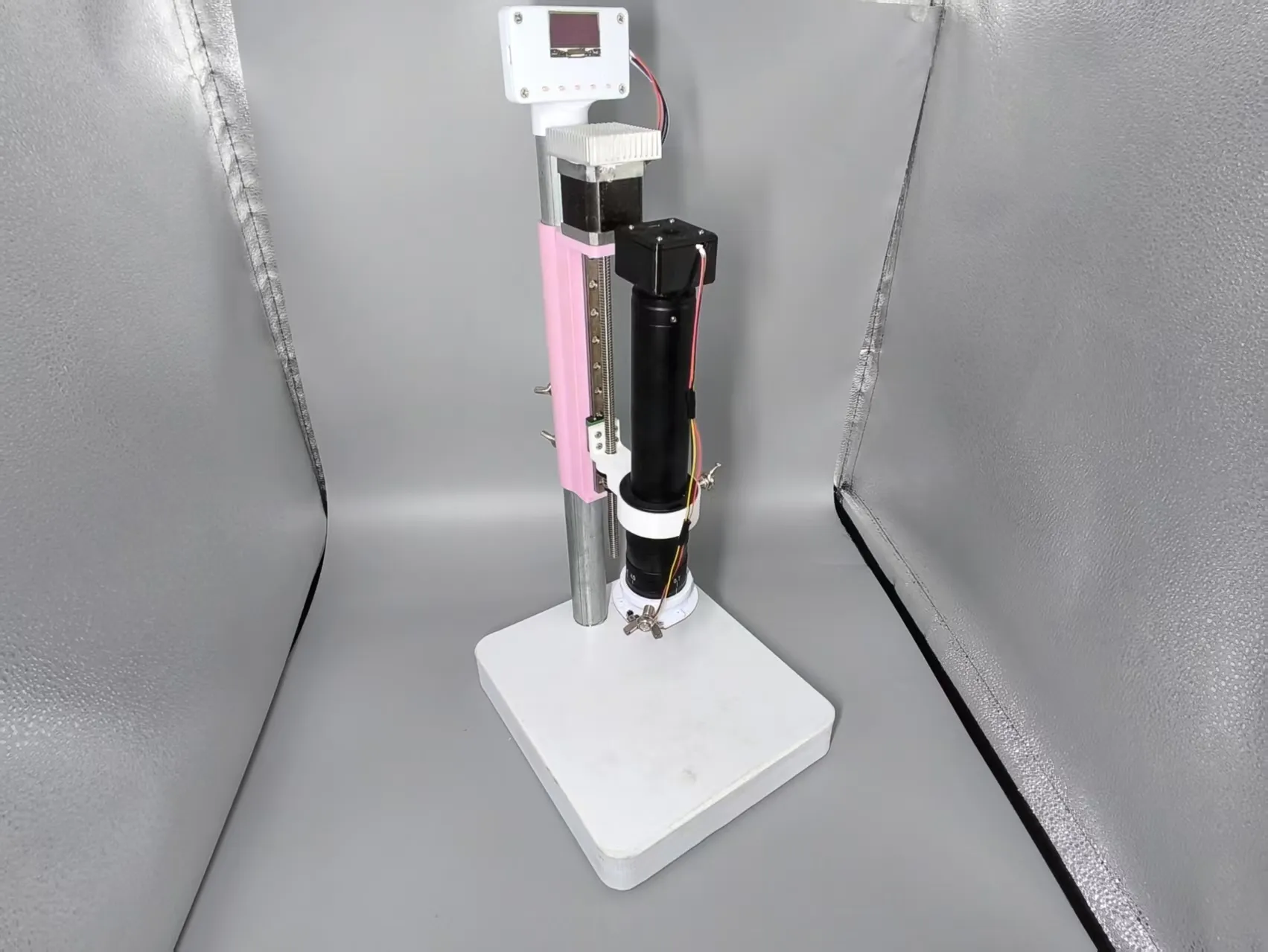
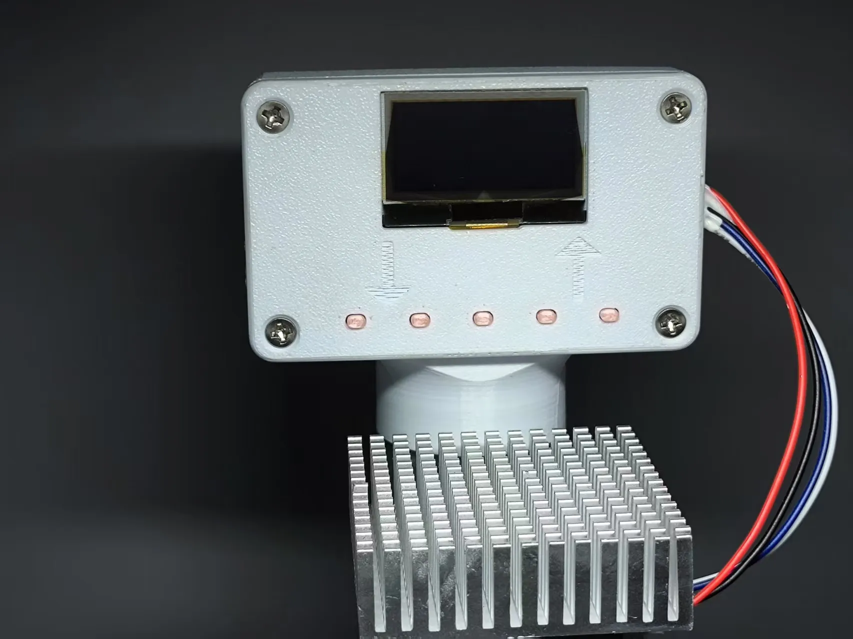
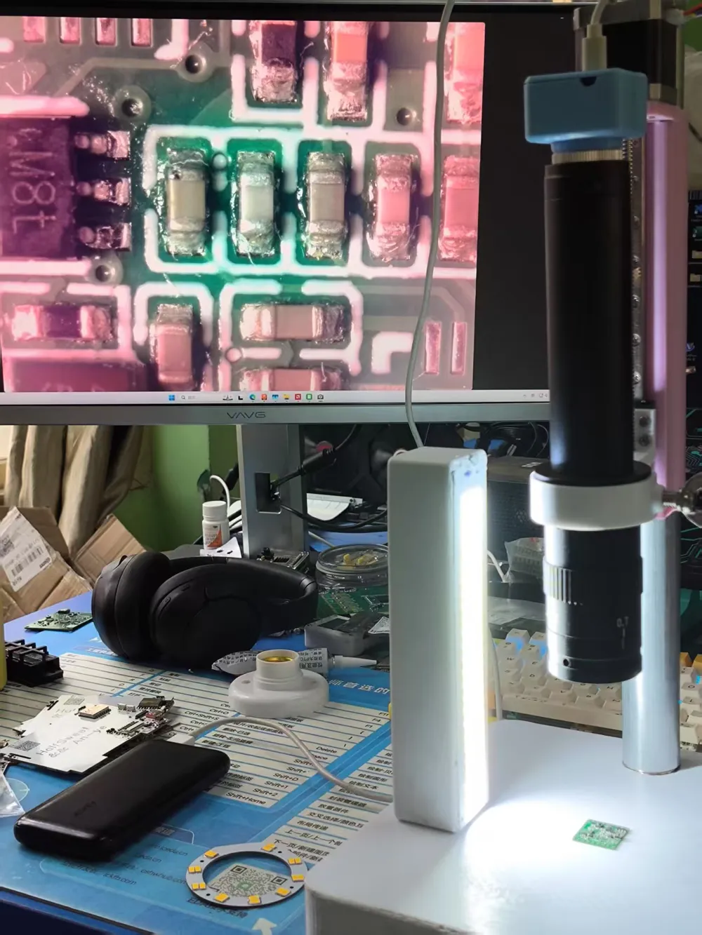
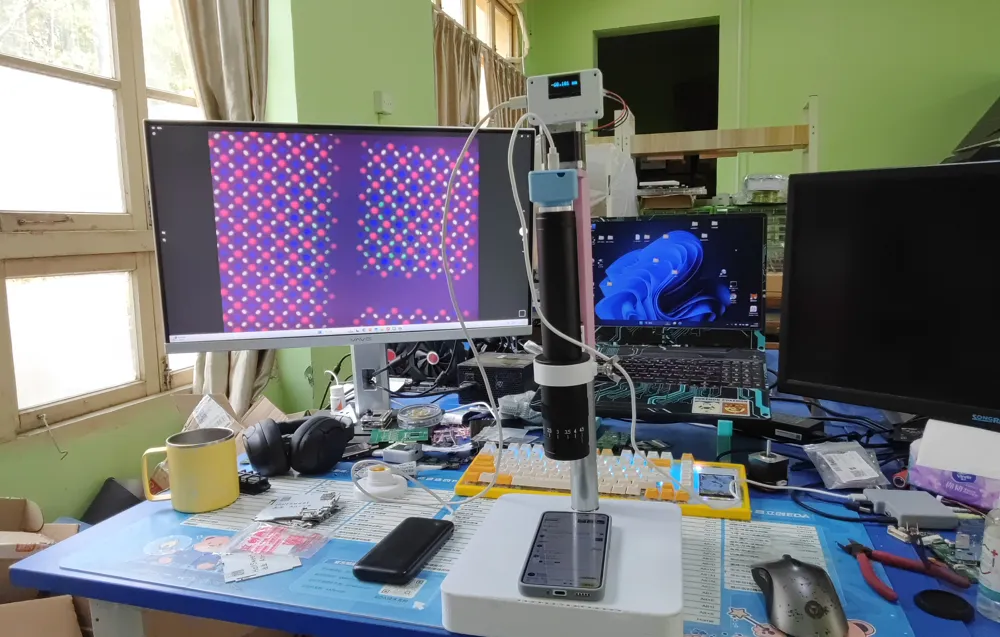
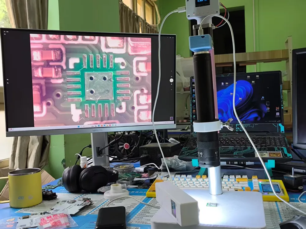
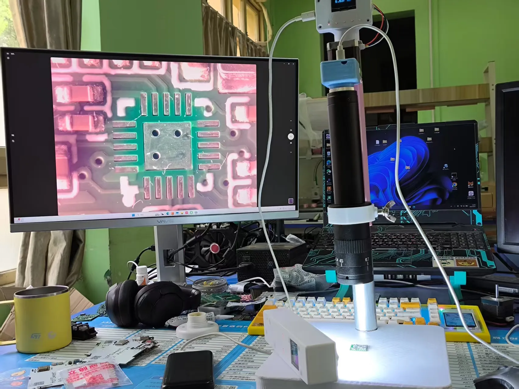
Let's look at the actual usage effect (note that the CMOS area needs to be printed in black to avoid light leakage, and try not to remove the IR cut filter, otherwise the corners of the image will appear red):
1x eyepiece 0.7x objective observed object: a PCBA with a large number of 0402 resistors and capacitors
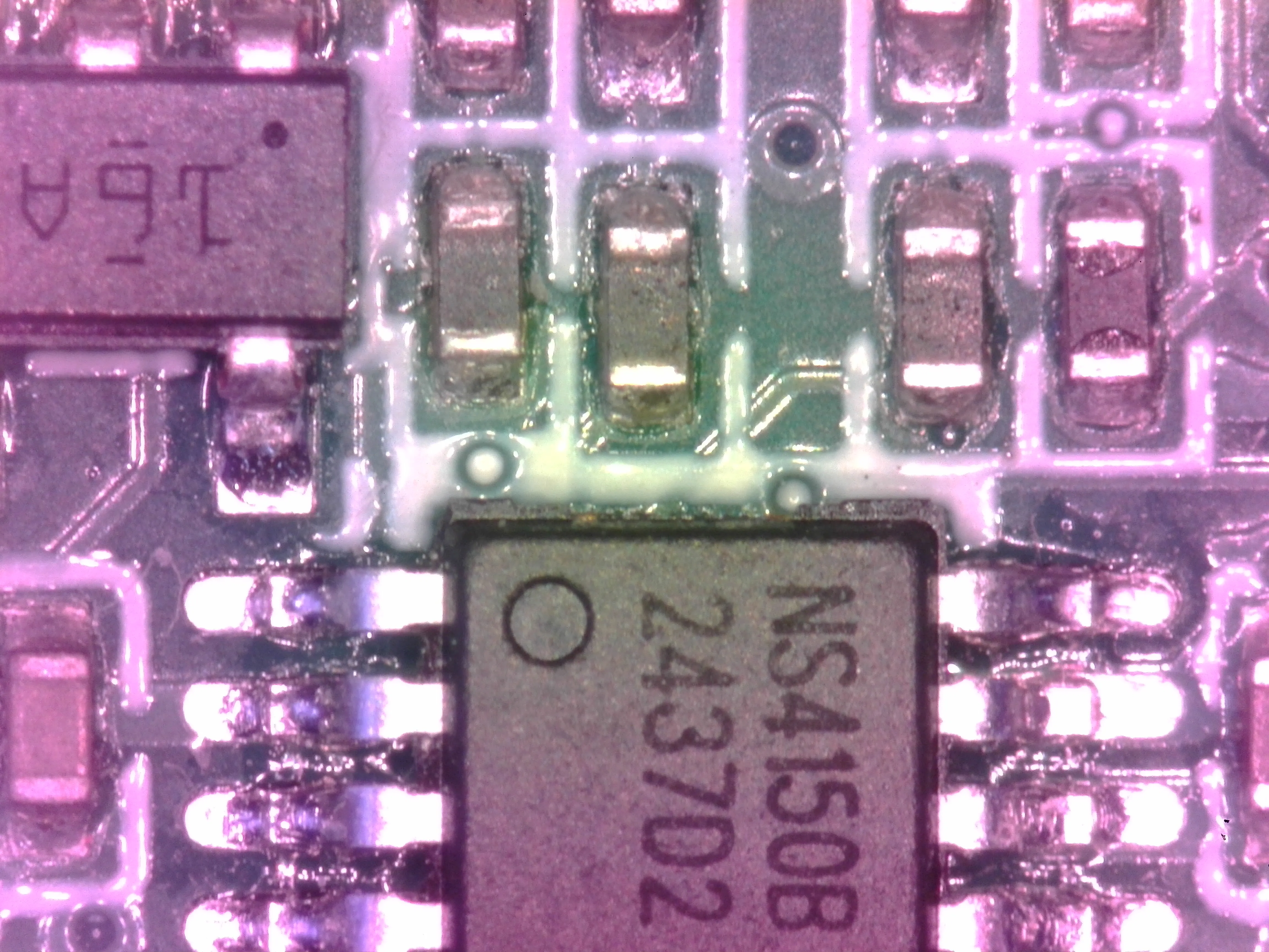
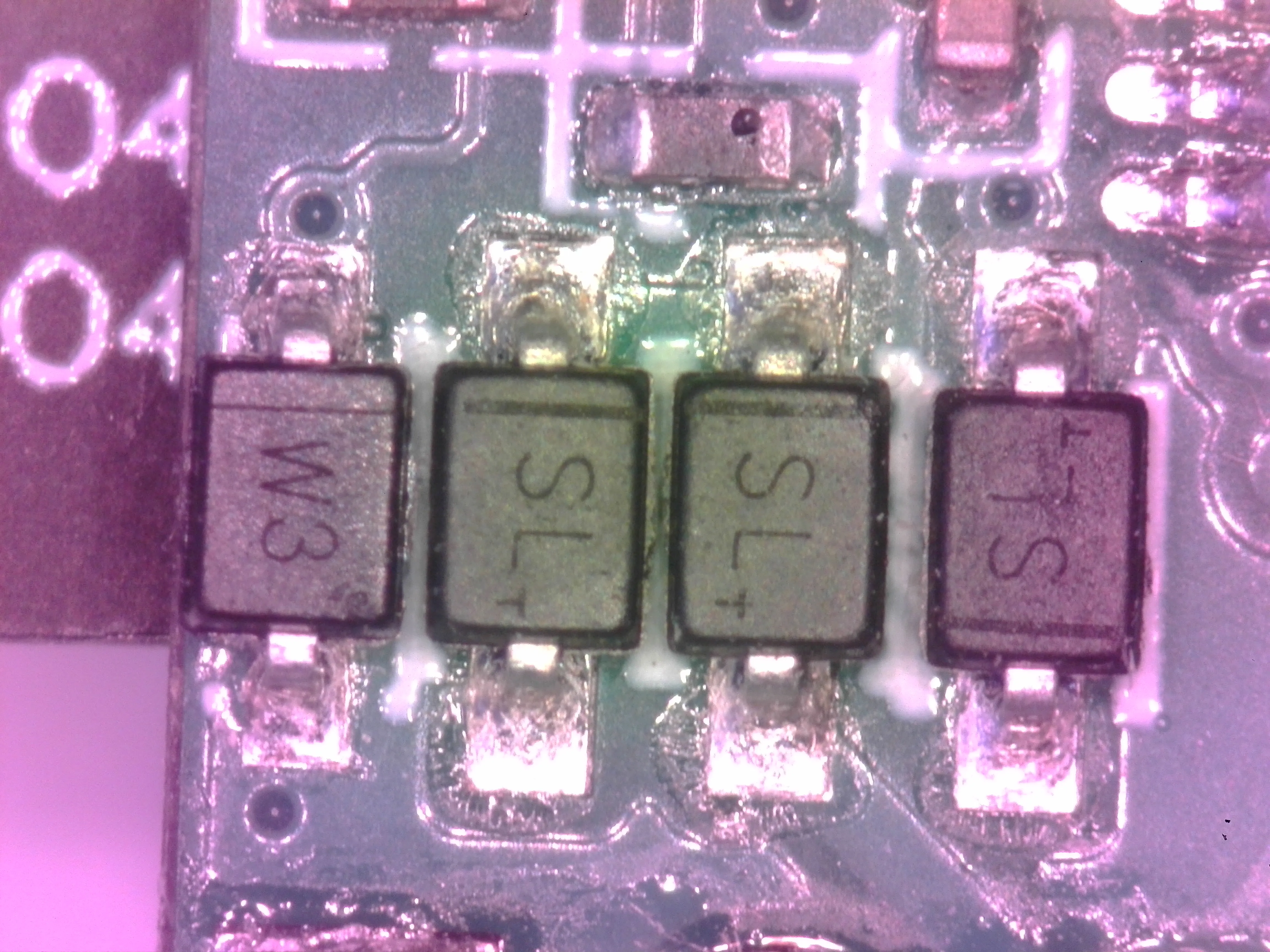
1x eyepiece 1x objective observed object: 4.2-inch tri-color e-ink screen
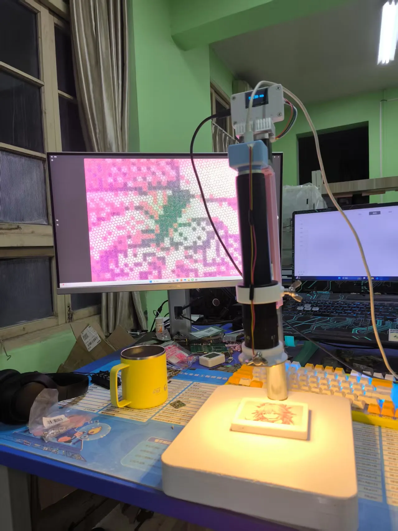
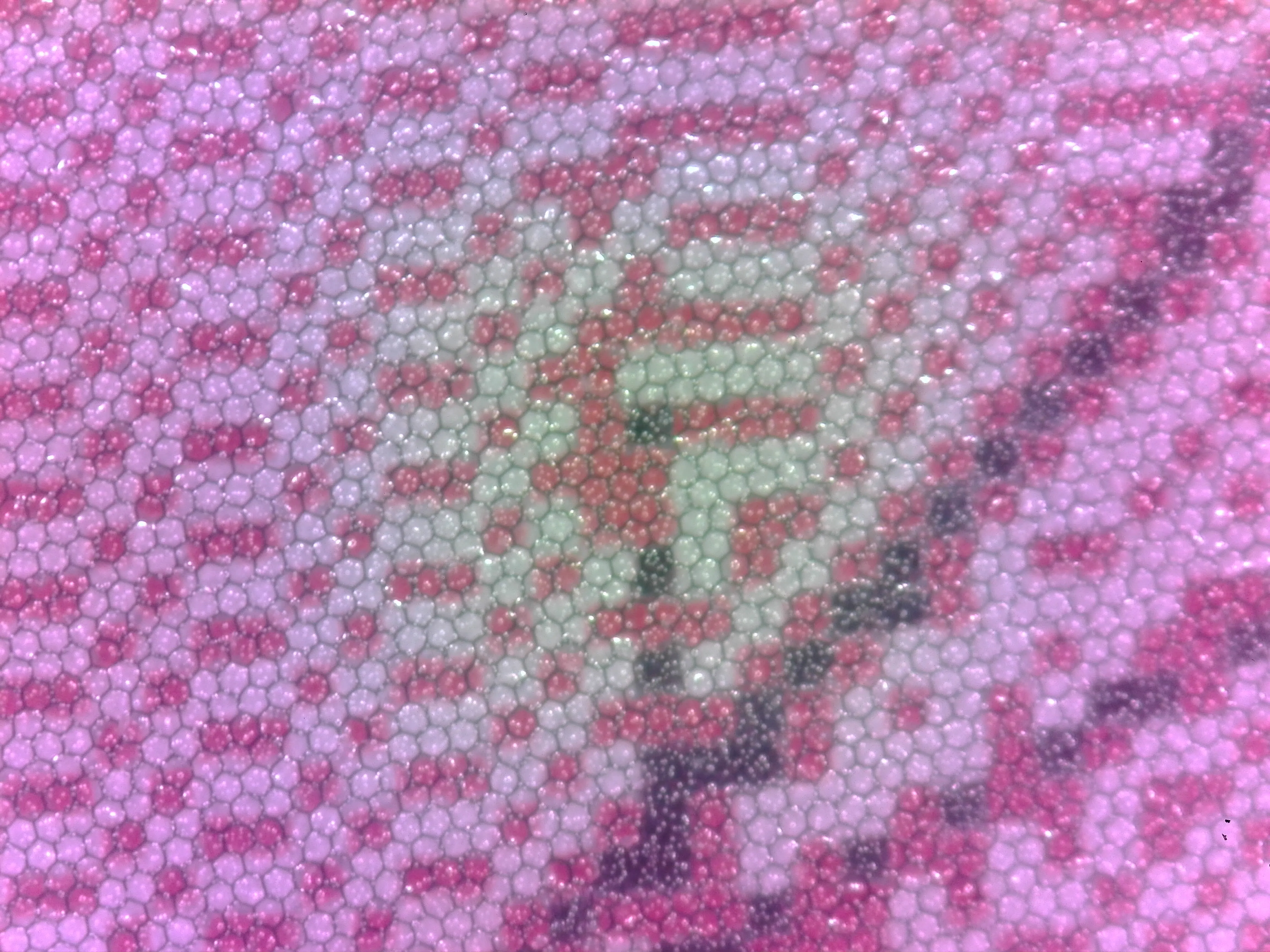
1x eyepiece 4.5x objective (highest magnification) observed object: Xiaomi 5 LCD screen
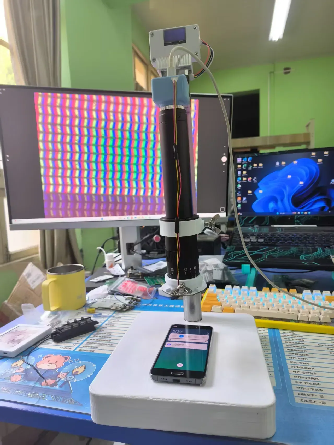
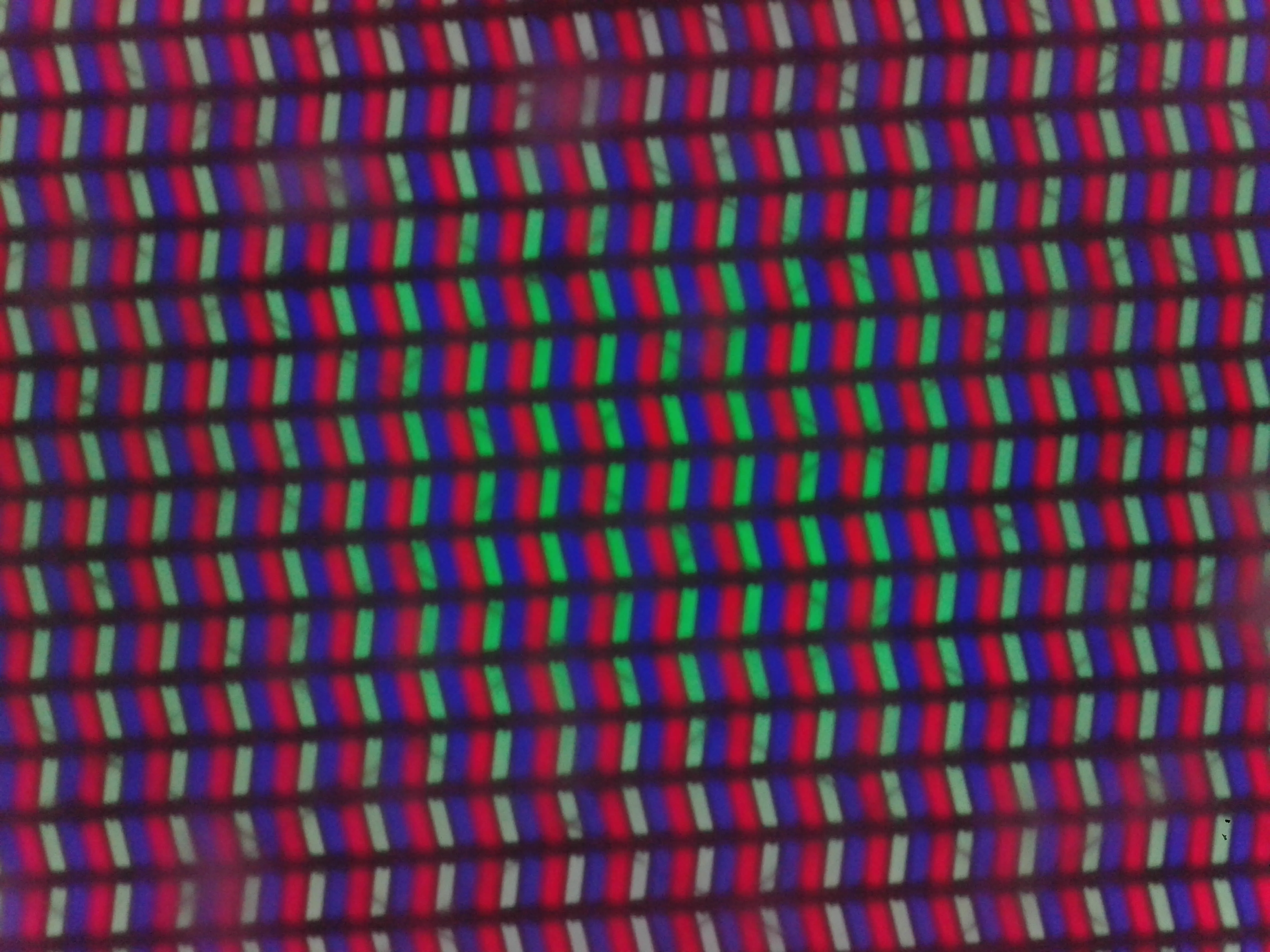
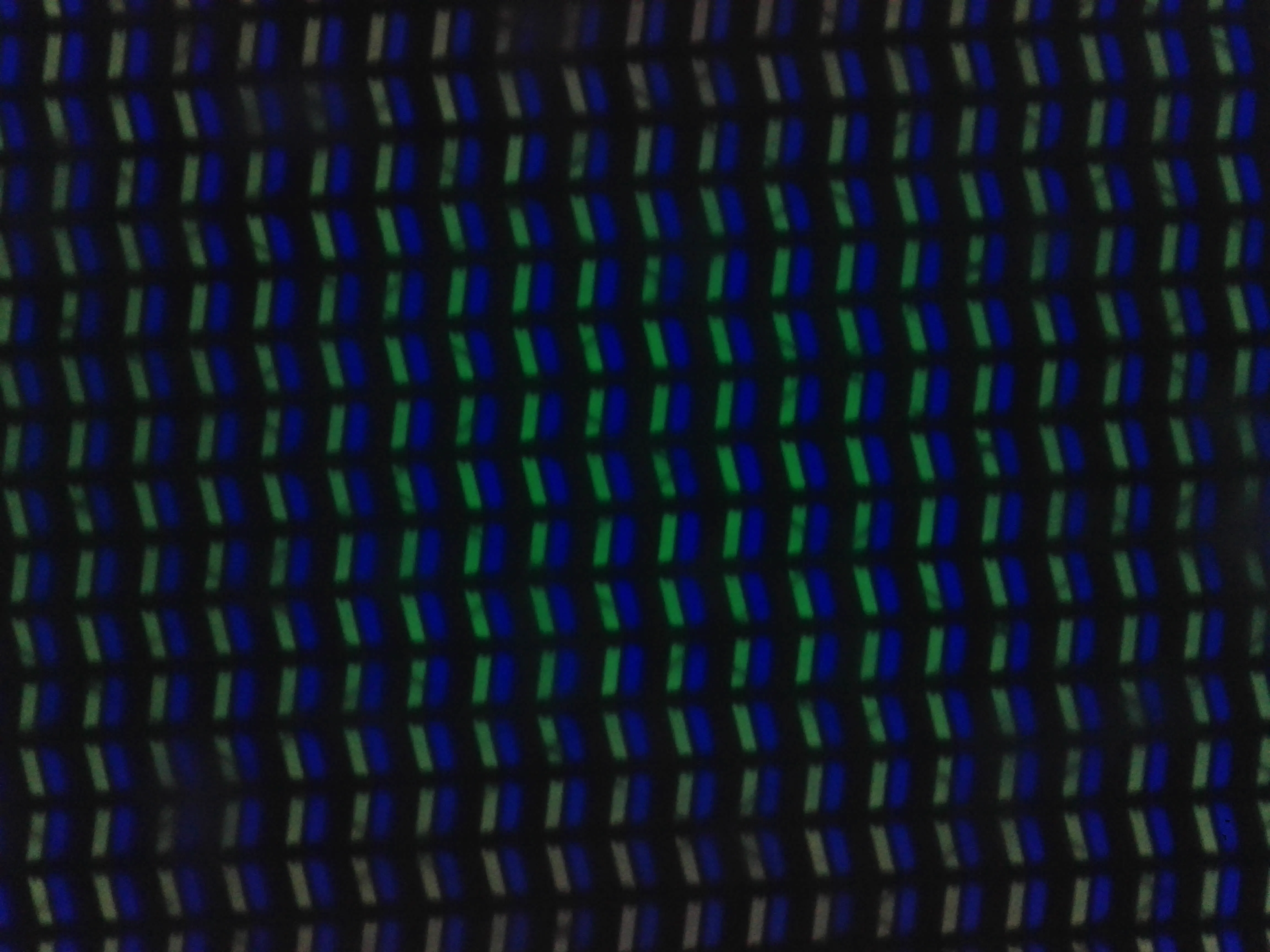
PS: Can clearly see a layer of capacitive touch layer on the screen? The texture caused the Mi 5 display effect to be not very good
1x eyepiece 4.5x objective (highest magnification) observed object: CSOT 2712*1220 6.67-inch AMOLED screen
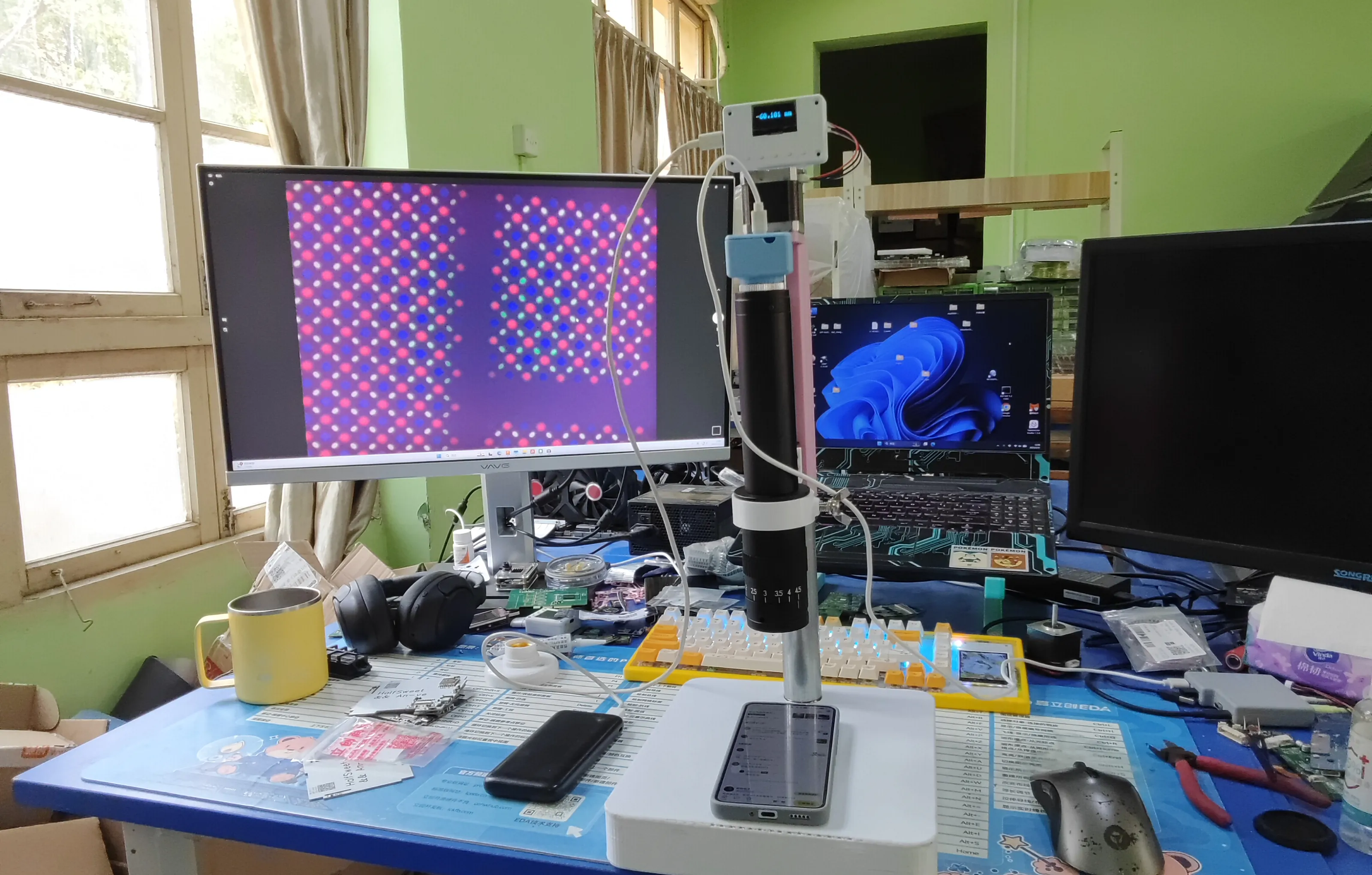
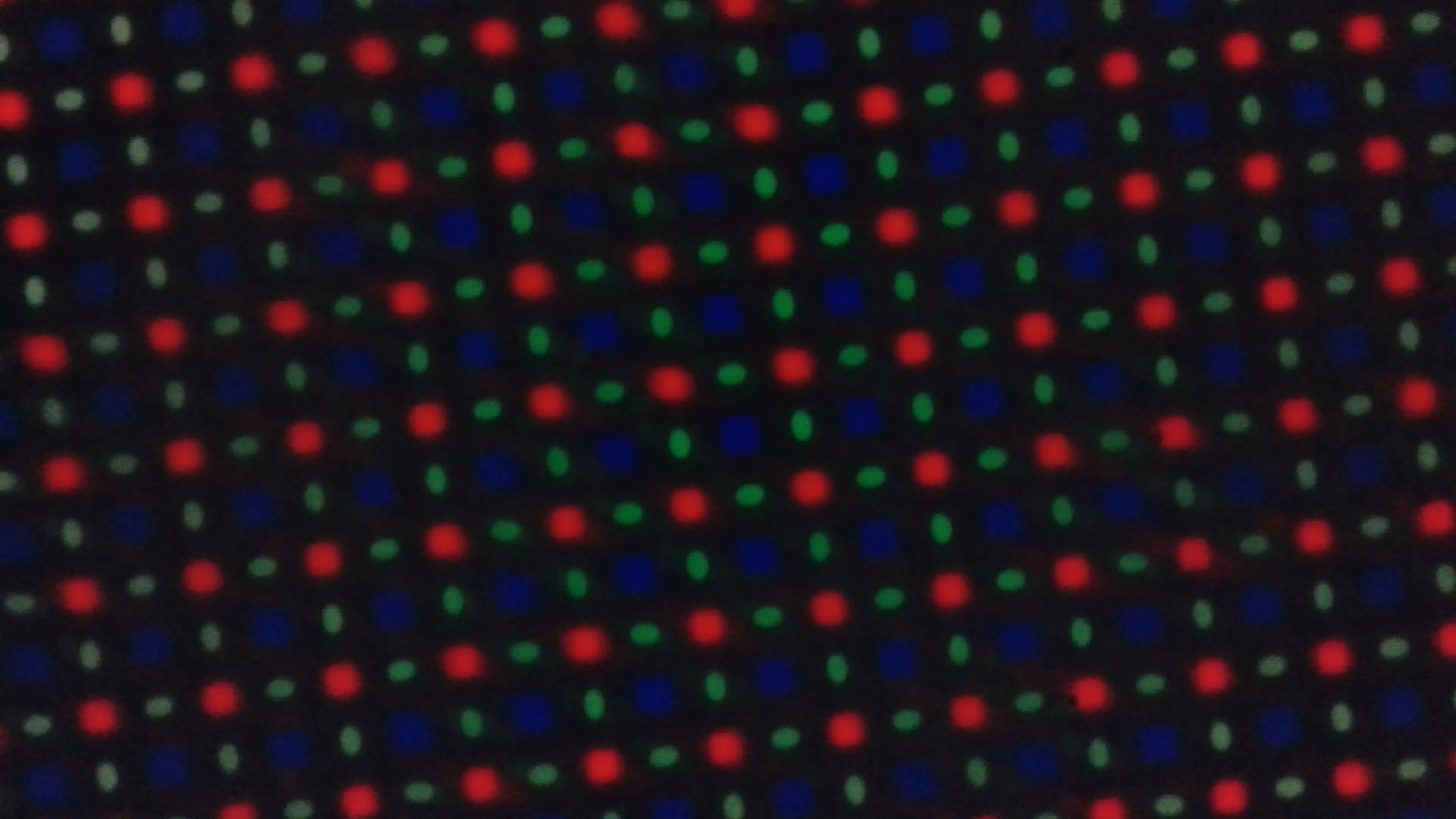
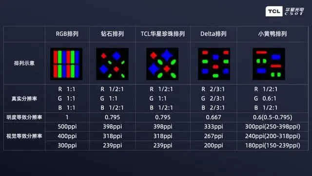
PS: Typical TCL pearl arrangement
Assembly instructions:
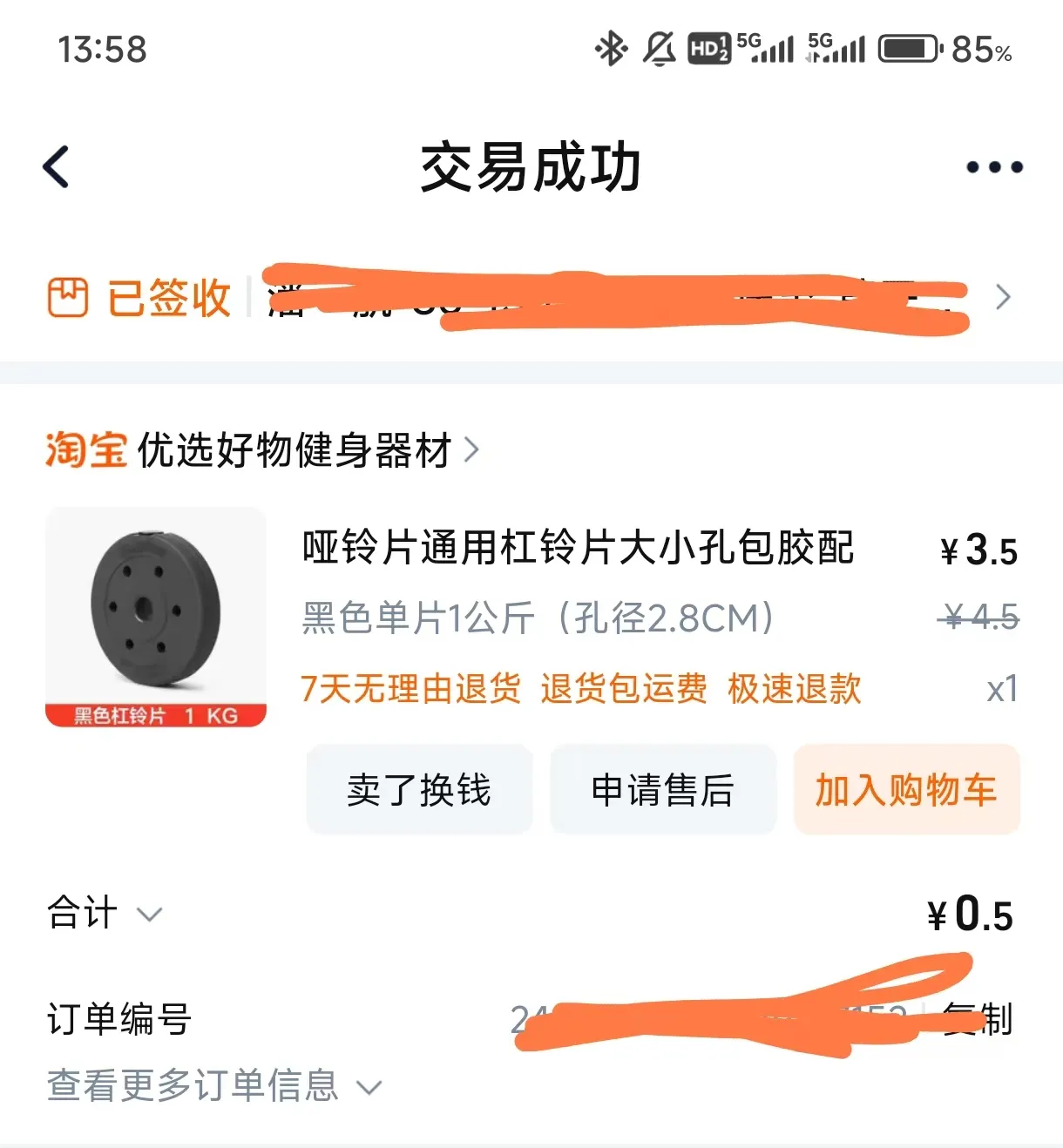
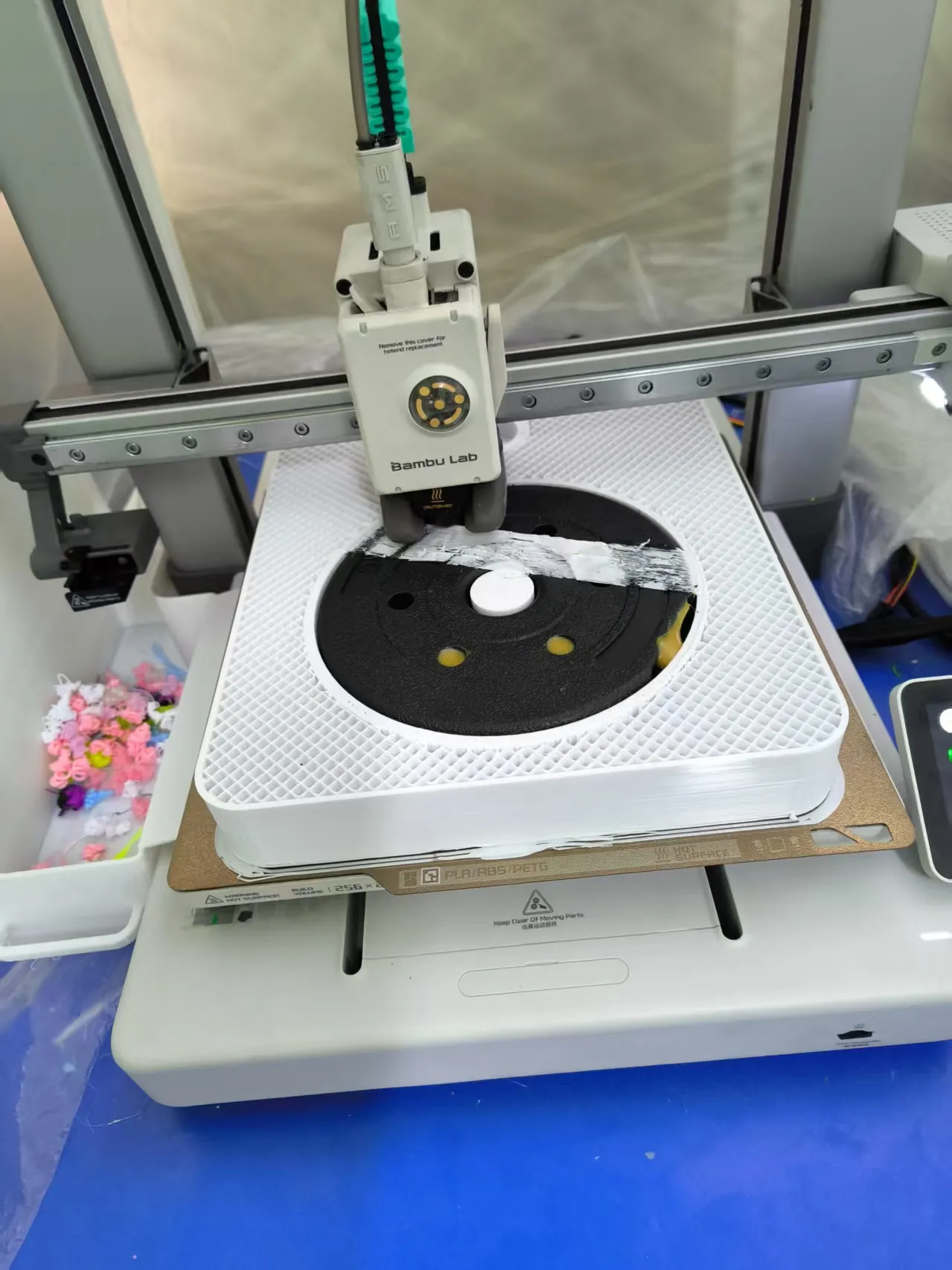
1. Print the base using white PETG. You need to purchase a 1kg dumbbell in advance and insert it during the pause layer. Special note: some vendors' dumbbells may have size deviations, so measure with calipers before printing to ensure it fits into the printed part. The dumbbell surface is a rubber-like material, which can be manually heated and trimmed. It should fit snugly into the printed part without shaking and needs to be glued in place, using industrial adhesive here
!! This is crucial. Thoroughly clean the build plate before printing. During ironing, you need to monitor to prevent over-extrusion. Manually intervene in printing if necessary (pause, cut, sand). The base requires 30h+ for printing and ironing, and consumes 800g+ of filament. Failure is very wasteful.
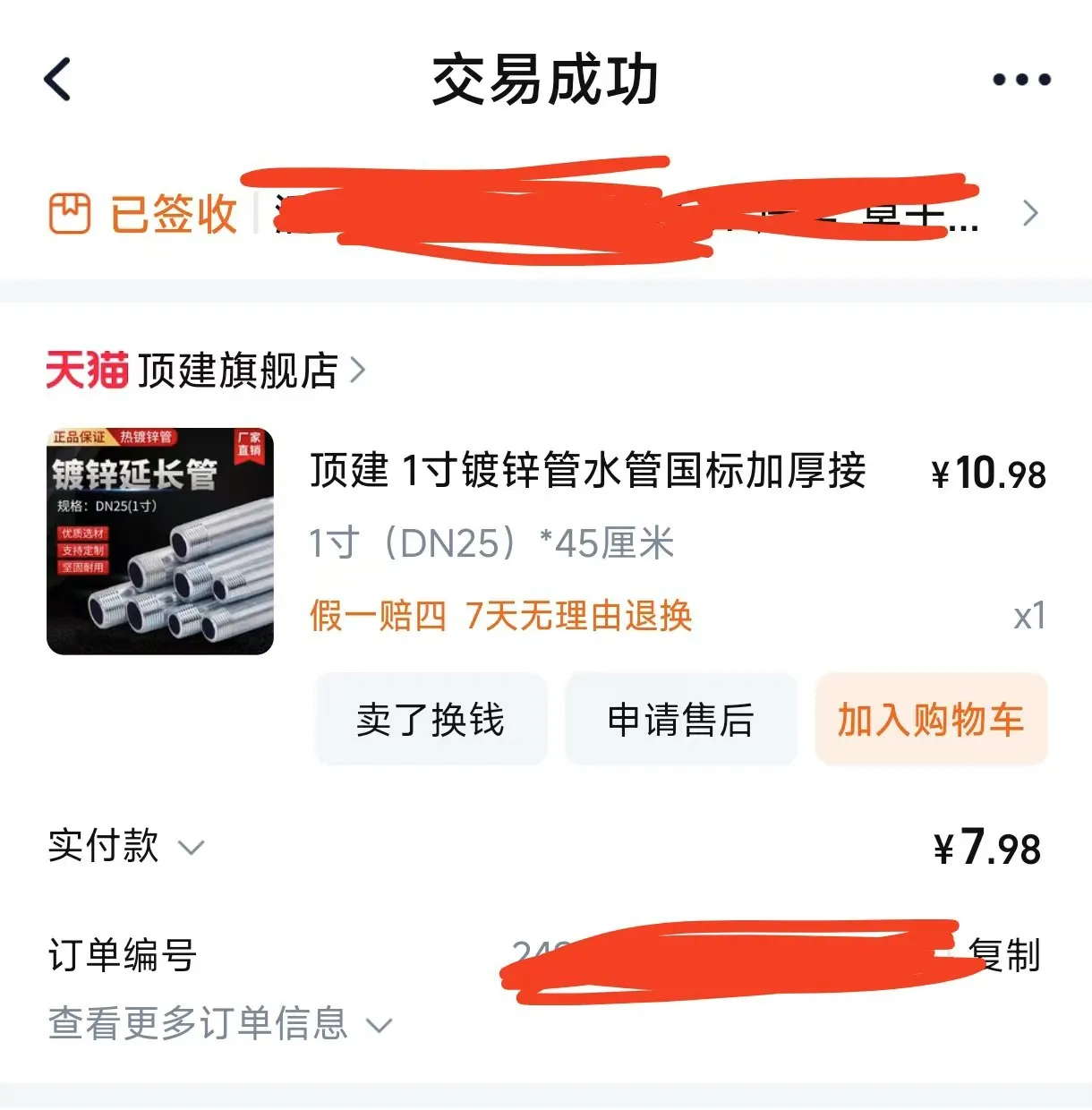
2. Purchase 1 steel pipe, with the same specifications as shown, screw it into the base, apply glue, and tighten
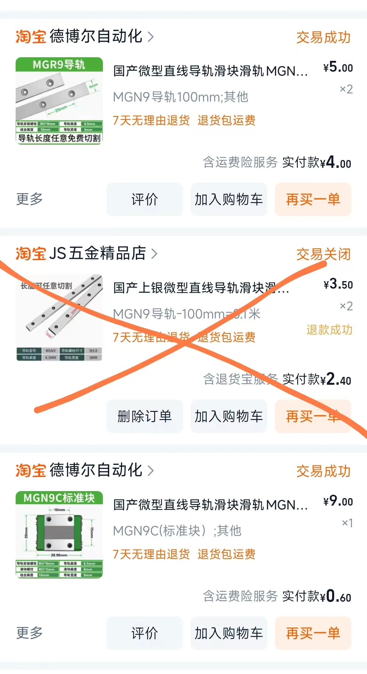
3. Print the remaining plate. First, snap the linear rail into the mounting groove, screw in all m3*8 screws, and tighten them. Remove the anti-backlash nut from the lead screw, reinstall it in reverse, and then install the lens movement bracket
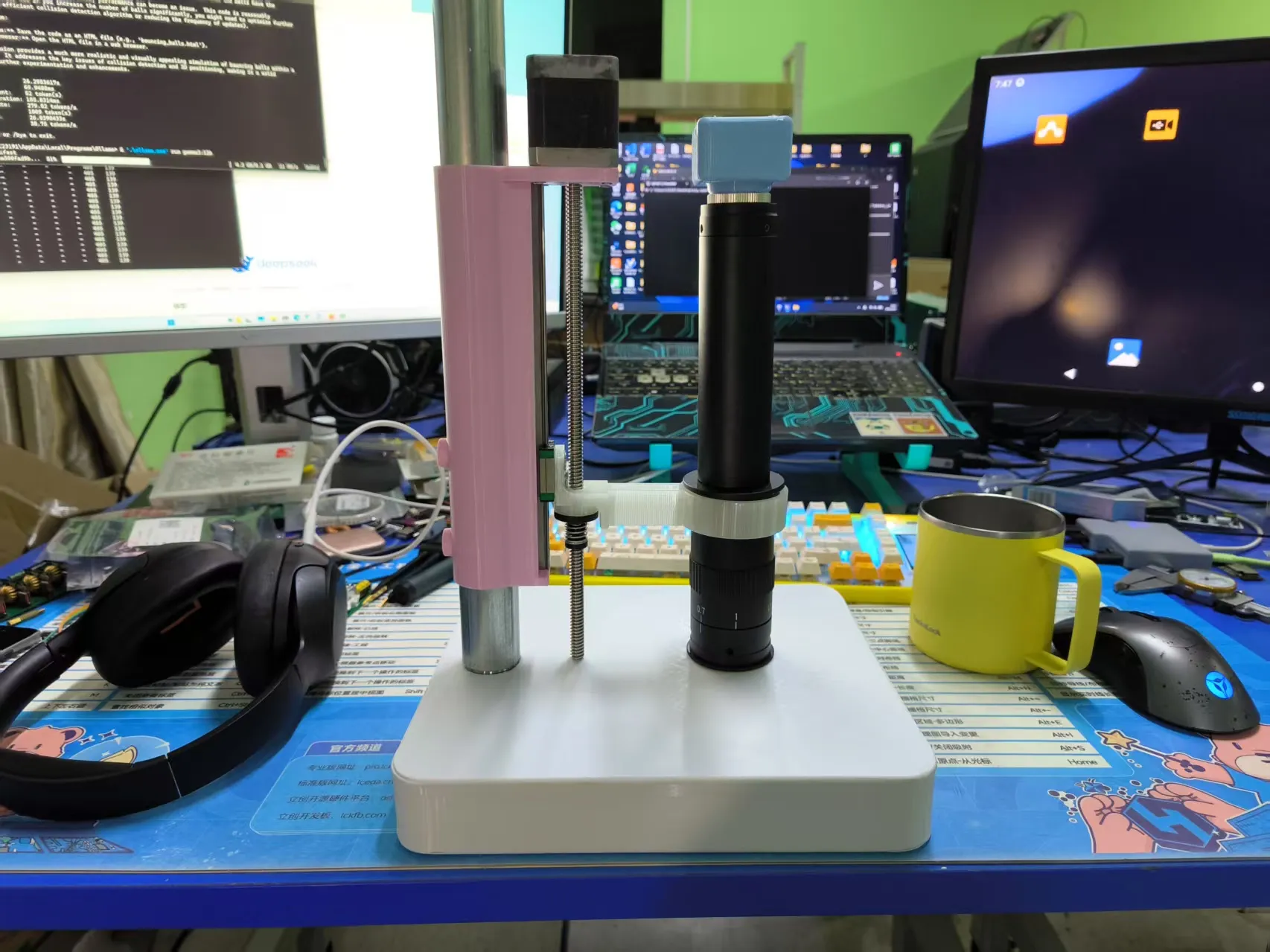
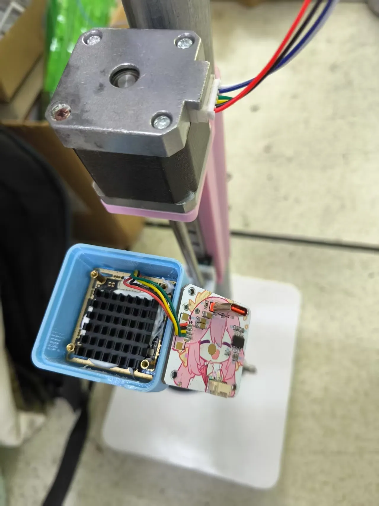
4. Install the camera board base, secure the CMOS board with m2*8+3 copper pillar screws (requires m2 standoffs), connect the LED adapter board, and apply thermal adhesive to secure the heatsink
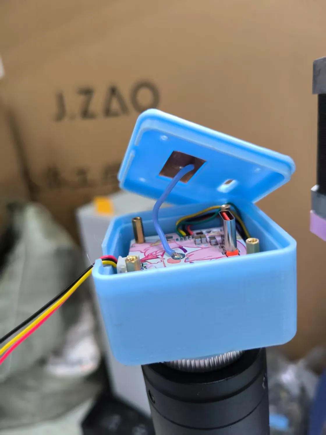
Connect the 3-pin cable of the LED board, solder the top cover touch, and secure the adapter board with m2*8+3 copper pillar screws
5. Connect the lens: You can buy a C/CS adapter or screw it directly. Be careful not to let dust enter the CMOS
6. Prepare the motor control board. After flashing the firmware, remove the pin headers, solder the ribbon cable provided with the stepper motor, and a 28*28*5.6 heatsink (LCSC part number C286194) can be fixed to the TMC2209 position on the back of the PCB with thermal adhesive
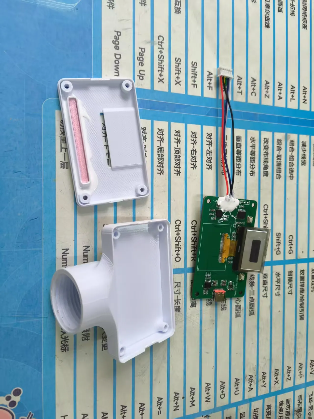
7. Installation and power-on (The motor driver board requires PD 20V power supply, with integrated decoy on the board, a power bank is recommended)
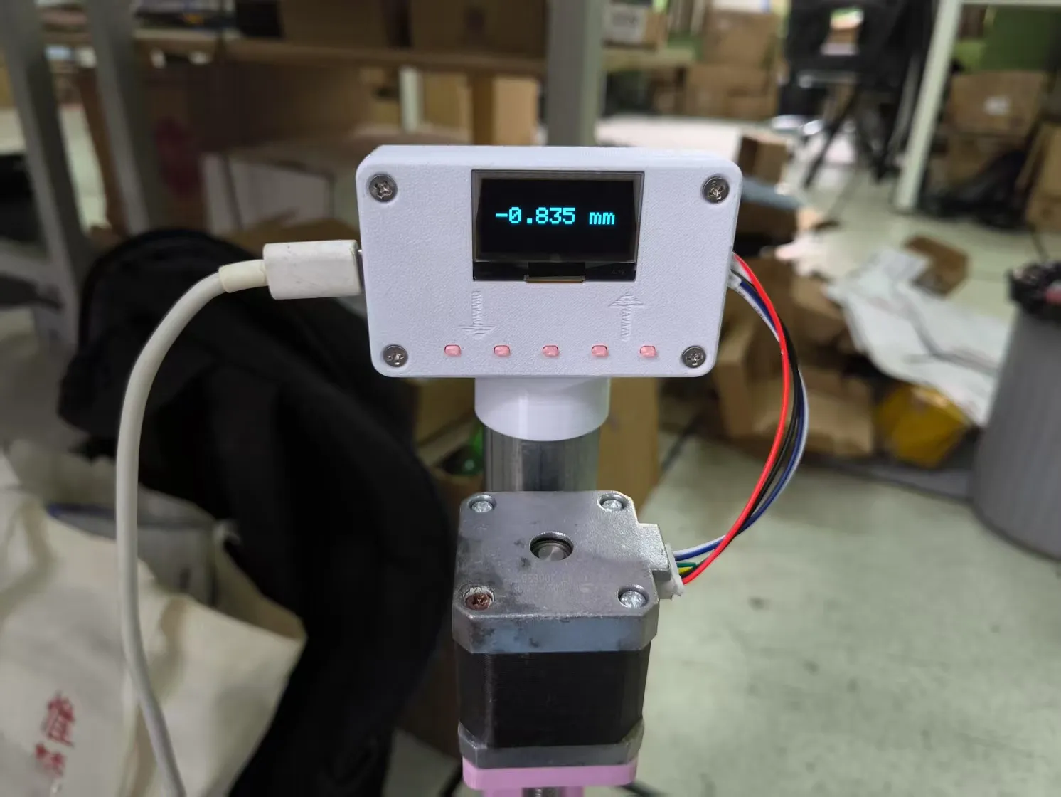
Button functions are: Fast Down - Down - (Hold BOOT on power-up to enter flashing mode) - Up - Fast Up
8. Install the lighting board, requiring a 30mm MX1.25 same-direction connector cable, or splice wires yourself. Connect the adapter board to the light board, install the lamp beads facing downwards, secure with 4 m2*6 screws from the bottom, and fix the lighting mounting part with m8*15 knurled screws
License

You shall not share, sub-license, sell, rent, host, transfer, or distribute in any way the digital or 3D printed versions of this object, nor any other derivative work of this object in its digital or physical format (including - but not limited to - remixes of this object, and hosting on other digital platforms). The objects may not be used without permission in any way whatsoever in which you charge money, or collect fees.


Comment & Rating (0)