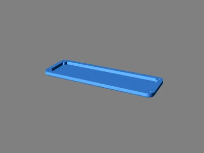
32 x 8 Led Matrix Case with MCU


Print Profile(1)
Description
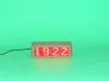
This is a case for a 32 x 8 LED matrix and an ESP8266 MCU. It runs on 5V (USB). I've made a connected clock with it. Its purpose is obviously a matter of the software running on the MCU.
You'll need to compile, upload a program to the ESP8266 and solder the connection between the MCU and the LED matrix. You'll need some basic tools such as pliers, a soldering iron and screwdrivers. Some CA glue, 2 - M3 x 6 mm screws, 4 - M3 x 8 mm screws, 5 - 6 cm wires, a small zip tie and a USB type A cable are required.
The LED matrix display is made of 4 - 8 x 8 matrices mounted on a single PCB. They're often sold with some headers already installed on the input pins. It is preferable to remove them and solder the connection to the MCU using the header holes in the PCB.
Here are some assembly instructions. They'll have to be adapted depending on the hardware you have.
- Support that touches the build plate is recommended.
- 20% infill is recommended, except for the lens.
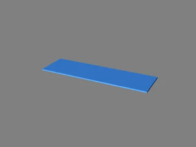
- The front lens is printed using transparent PETG. I suggest you to use the same colour as the colour of the LED. Print it at the highest quality on a smooth plate with 100% infill.
- Remove the support in the screw hole of the back cover (BackCover.stl).
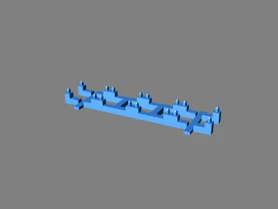
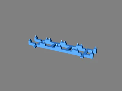
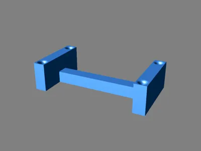
- Glue LedMatrixHolderBrace.stl to the LedMatrixHolder_WWmmxHHmmxMDmm.stl. There are two versions of it. WW is the distance across the mounting holes of an 8 x 8 matrix, HH is the distance of the mounting hole on the top and the bottom, and MD is the distance between the mounting holes of two adjacent matrices. The distance is measured from the centre of the mounting holes. The braces must be glued in the opposite direction of the pins that hold the display on the holder. They are glued in the groves of the LED matrix holder.
- Remove the input headers of the display module if they were installed.
- Connect the ESP8266 to the LED matrix module: Module DIN to MCU D7, module CS to MCU D6, module CLK to MCU D5, Module VCC to MCU Vin, Module GND to MCU GND, USB GND to MCU GND, and USB VCC to MCU VCC. These connections may be changed as long as the software is updated accordingly. INSERT THE USB CABLE IN THE HOLE OF THE CASE BODY BEFORE SOLDERING IT.
- Install the clock software on the MCU and test if everything works fine before continuing the assembly. You might have to rotate the display using the variable ROTATE in the max7219.h source file. John Rogers' software is available at https://github.com/K1WIZ/ESP8266-8x32-Matrix-clock along with some instructions.
- Install the MCU to the MCU holder (ESP8266Holder.stl) using two M3 x 6mm screws.
- Insert the matrix module on the LED Matrix Holder and glue the MCU assembly on the same side of the braces. Make sure that the USB connector of the MCU is away from the connection of the LED matrix. You will need space to connect a USB cable to the MCU if you need to reprogram it.
- Insert the lens (Lens_1.5mm.stl) in the case main body.
- Insert the electronic module in the case main body until the display touches the lens.
- Put a few drops of glue to on the braces to hold the electronic display tight on the lens. Hot glue is a good choice since it can be easily removed. You can also use the ElectronicModuleHolder.stl.
- Use a zip tie as a strain relief on the USB cable.
- Close the back cover with 4 - M3 x 8mm screws.
This object's main web page is:
http://www.ctheroux.com/32-x-8-led-matrix-case-with-mcu/.
This object was designed using Solid Edge Community Edition.
You can request the source files on the page listed above.
Comment & Rating (2)