Mechanical Flower


Print Profile(1)

Bill of Materials


Description
Bring motion to life with this vibrant 3D printed mechanical flower! Featuring bold red petals and a gear-driven core, it gracefully rotate through an elegant system of linkages. Requires additional Maker’s Supply parts like a Power Distribution Board, N20 Reduction Gear Motor, and Potentiometer Board — check the BOM for full details.
Assembly Guide:
- All Parts

2. Connect the Self-locking Button Switch to the SW0 (main switch) port on the Power Distribution Board.

3. Detailed close-up photo
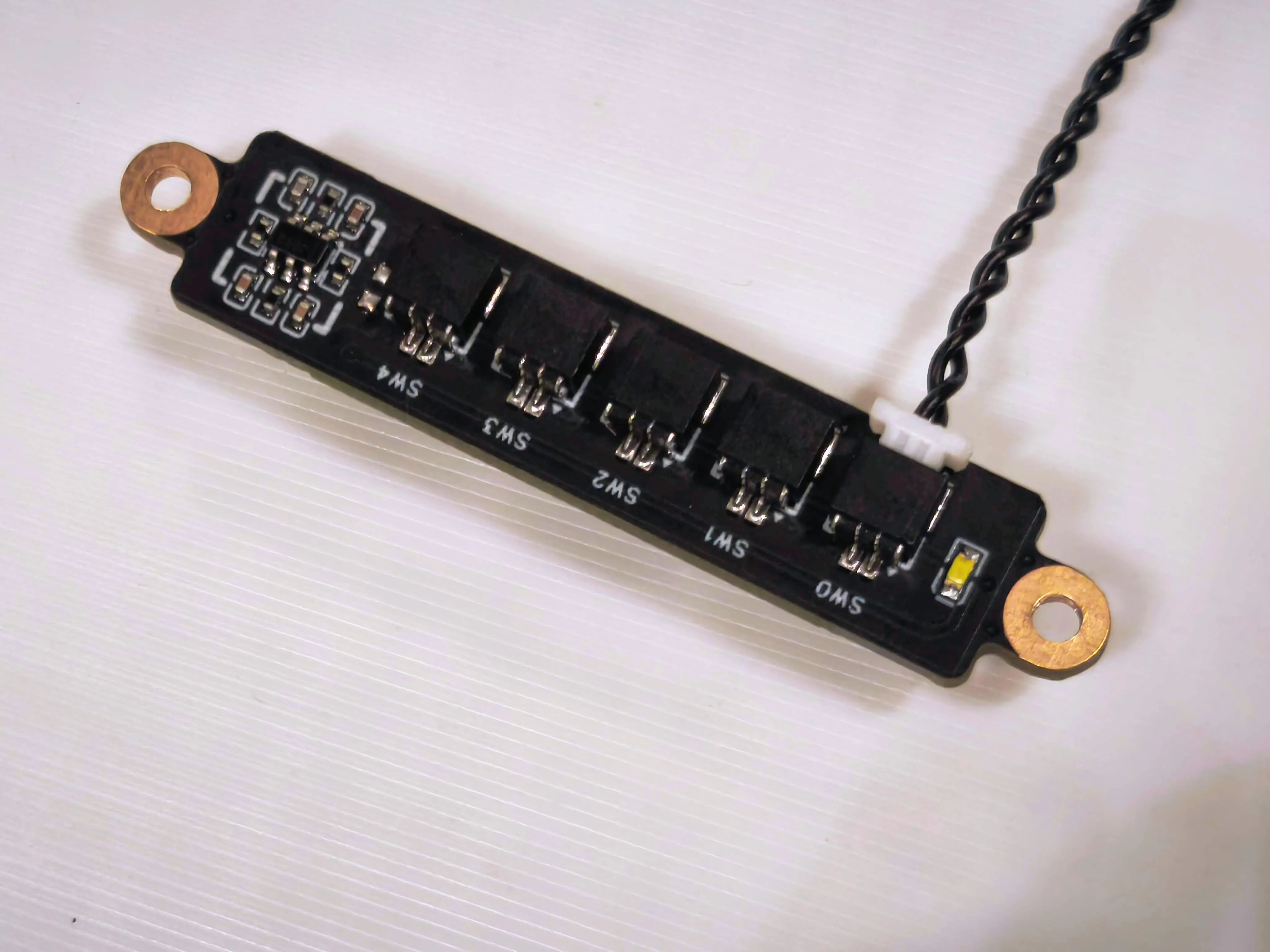
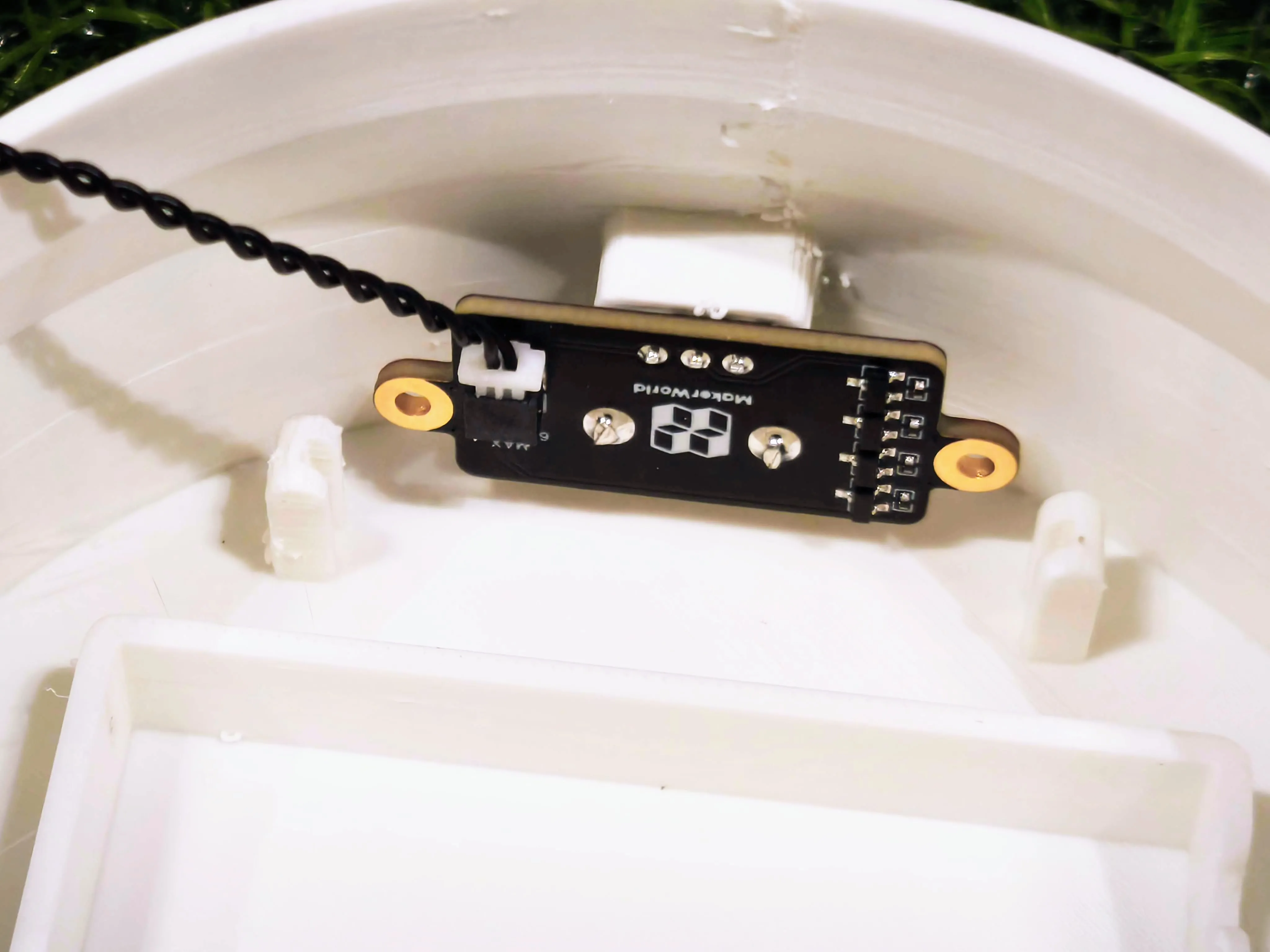
4. Connect Potentiometer to the SW4 port on the Power Distribution Board.

5. Detailed close-up photo

6. Connect the jumper cable to the SW1, SW2, and SW3 ports as appropriate

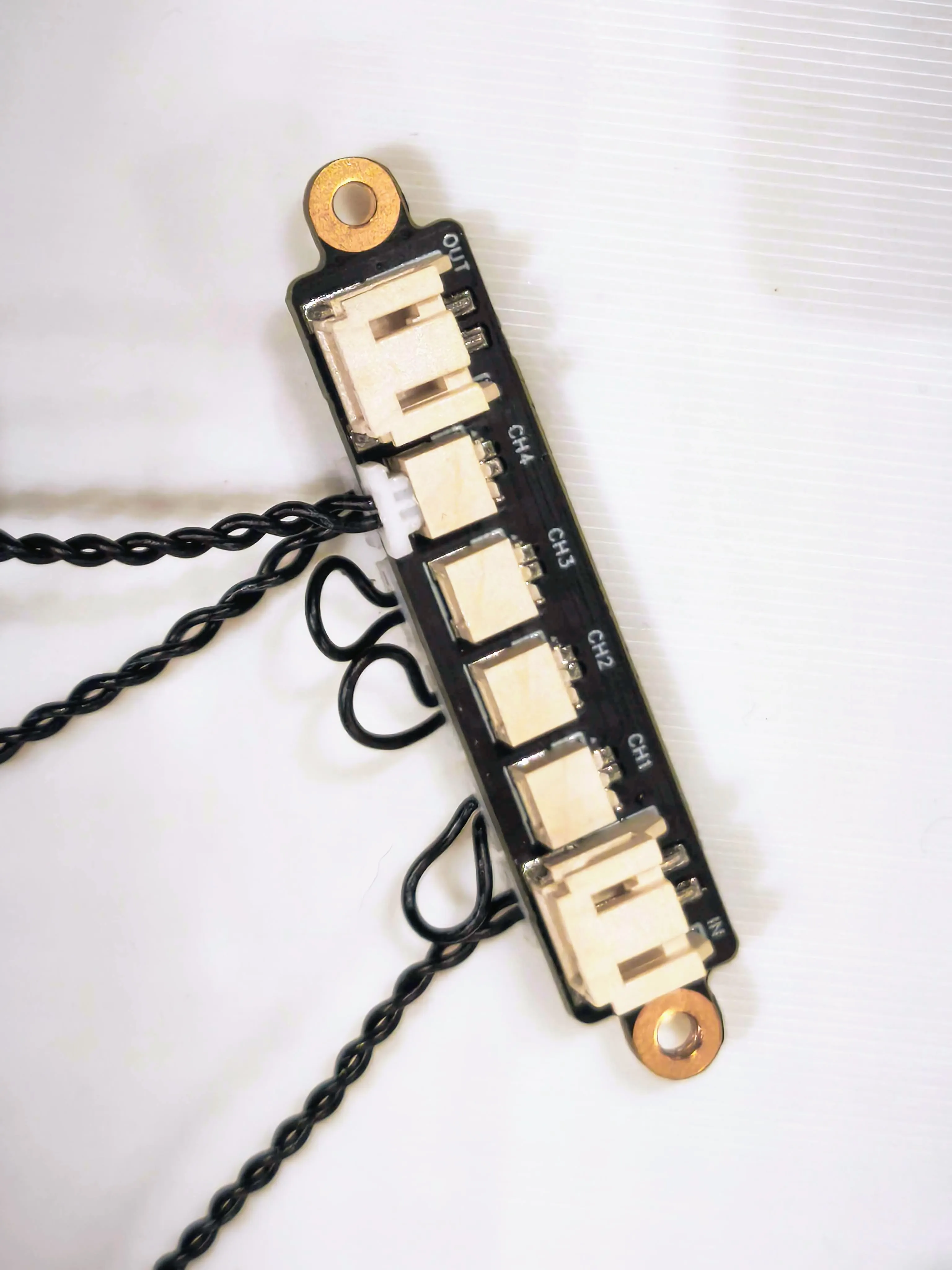
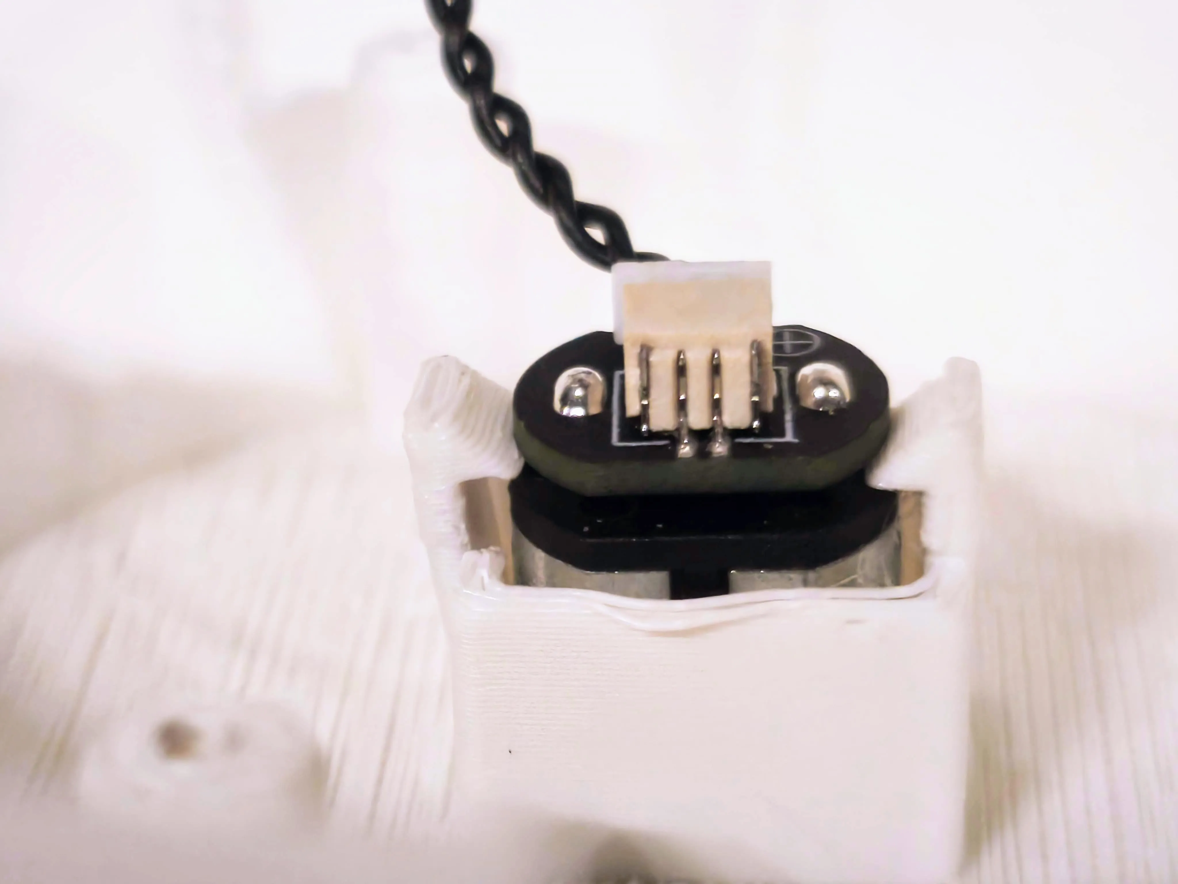
7. Connect the N20 Reduction Gear Motor to the CH4 port on the Power Distribution Board.

8. Detailed close-up photo
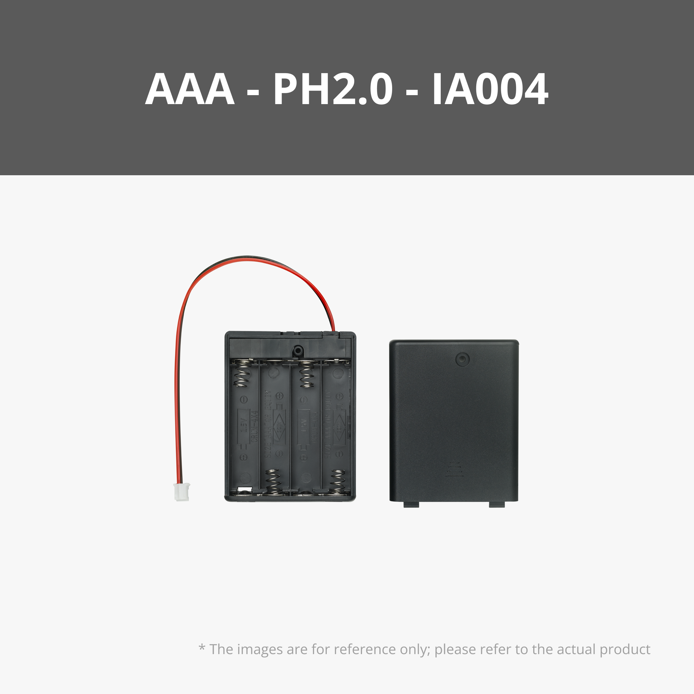
9. Connect the AAA Battery Case to the “IN” port on the Power Distribution Box

10. Detailed close-up photo

11. Insert 4 x AAA batteries into the battery case, then press the switch button. Check if the LED lights on the Power Distribution Board turn on and if the motor is rotating.

12. Carefully insert the gear motor into the frame, aligning it with the snap lock on the top casing. Gently pull back the snap lock pins to allow the motor to slide securely into place.

13. Insert the gear motor all the way in until it reaches the gap, as shown in the photo.
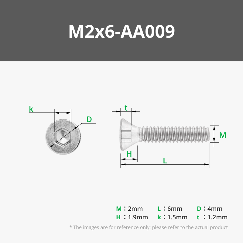
14. Secure the Power Distribution Board to the mounting posts on the top casing using two M2x6 screws.

15. Insert the potentiometer into the designated slot in the frame on the bottom casing.
16. Slide the panel behind the potentiometer to hold it securely in place.

17. Insert the Self-locking Button Switch into the designated slot in the frame on the bottom casing.

18. Slide the panel behind the button switch to hold it securely in place.

19. Place the AAA battery holder into the designated slot on the bottom casing.

20. Mount the white core onto the gear motor on the top casing. Then, snap the top casing onto the bottom casing to secure it in place.

21. Mount the spirals onto the five inner ring posts surrounding the central core post.

22. There are A and B pedals, with five of each.

23. There are A and B pedals, with five of each. Mount them onto the outer ring posts one by one in alternating order: A, B, A, B, and so on.

24. Avoid placing two petals too close to each other, as this may cause them to collide and stop the spinning.

25. Press the switch to enjoy your mechanical flower in motion!

License
You shall not share, sub-license, sell, rent, host, transfer, or distribute in any way the digital or 3D printed versions of this object, nor any other derivative work of this object in its digital or physical format (including - but not limited to - remixes of this object, and hosting on other digital platforms). The objects may not be used without permission in any way whatsoever in which you charge money, or collect fees.
Comment & Rating (6)