
RC electric glider fuselage
Print Profile(1)

Description
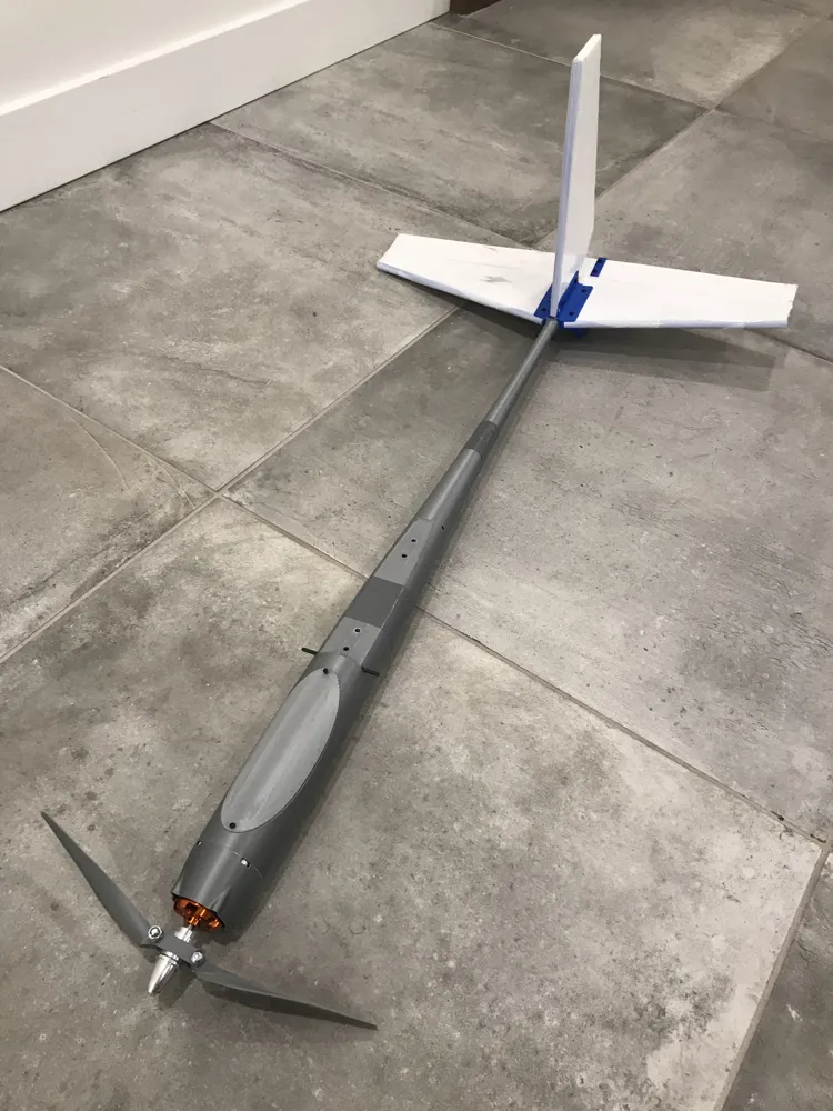
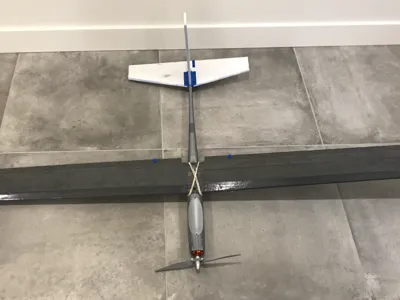
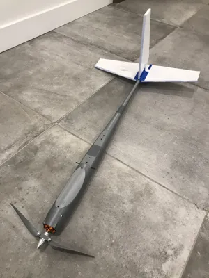
This is a modular fuselage for a simple but very capable RC electric glider. You can attach any type of wing and tail you want after.
Needed to build the fuselage:
- 4x M4 nuts
- 4x M3 screws
- 2x M2 screws
- 42mm motor backplate mount
- Superglue
Assembly steps:
- Take the Front and Mid fuselage sections and glue two M4 nuts in each on the inside mounting holes. These are theoretically optional but allow for more mounting options for the wing you will choose.
- Glue three of the connectors halfway into the holes at the rear of the Front fuselage.
- Do the same at the rear of the Mid fuselage.
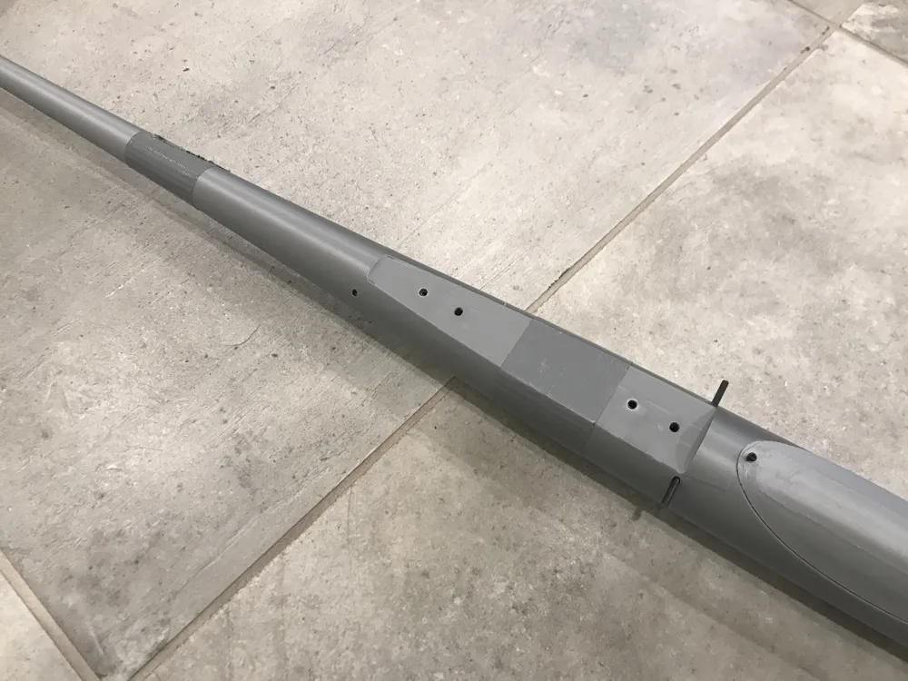
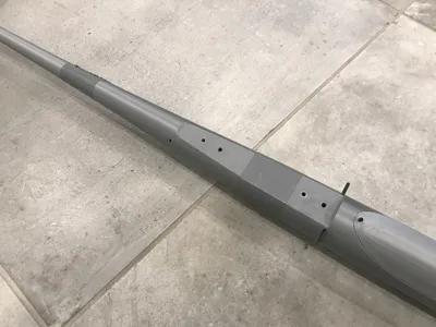
- Add glue on the remaining parts of the connectors sticking out of the Front fuselage and slide in the Mid fuselage. You can also add glue to the seam for added strength.
- Do the same with the Mid and Tail fuselage. Make sure the two holes at the other end of the Tail fuselage are oriented horizontally while doing so (this serves to mount the tail, wouldn't want it 120 degrees off).
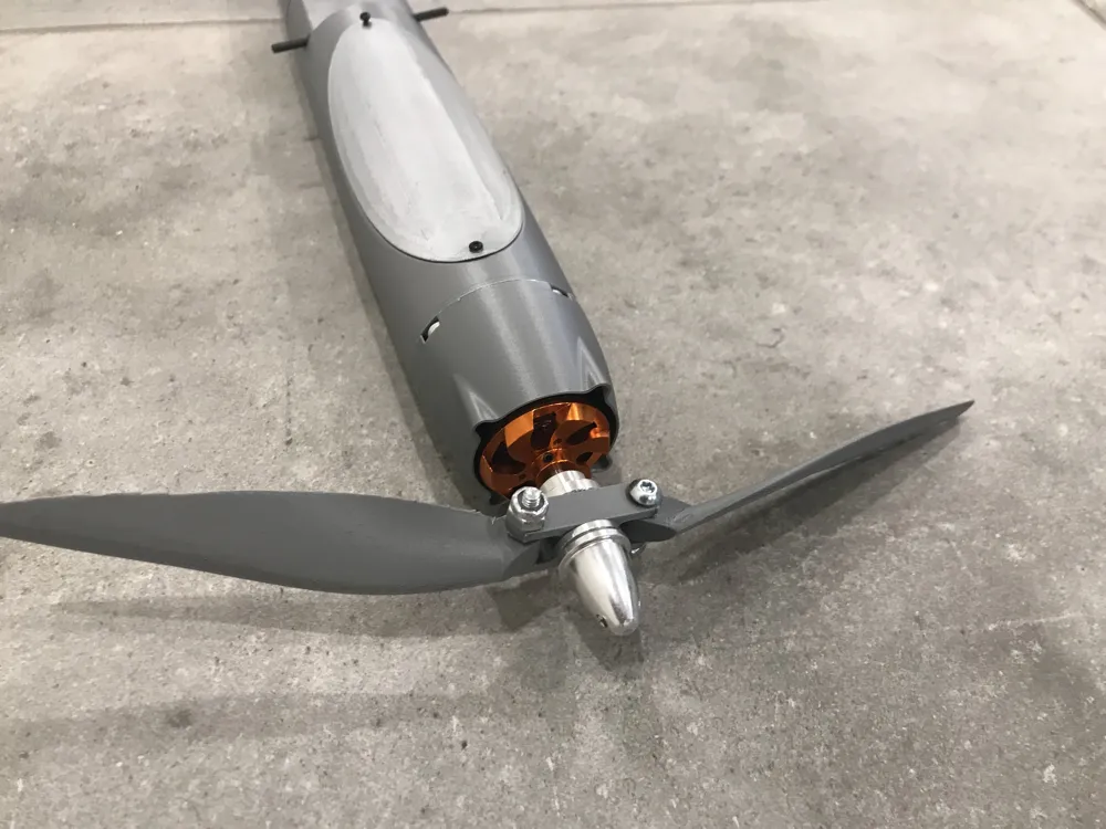
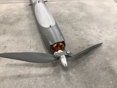
- Mount your motor backplate with its motor to the nose with the M3 screws. If you decide to add the cowling, you must first put the motor/backplate in place, then the cowling, and finally the screws to create a cowling - motor - fuselage “sandwich”.
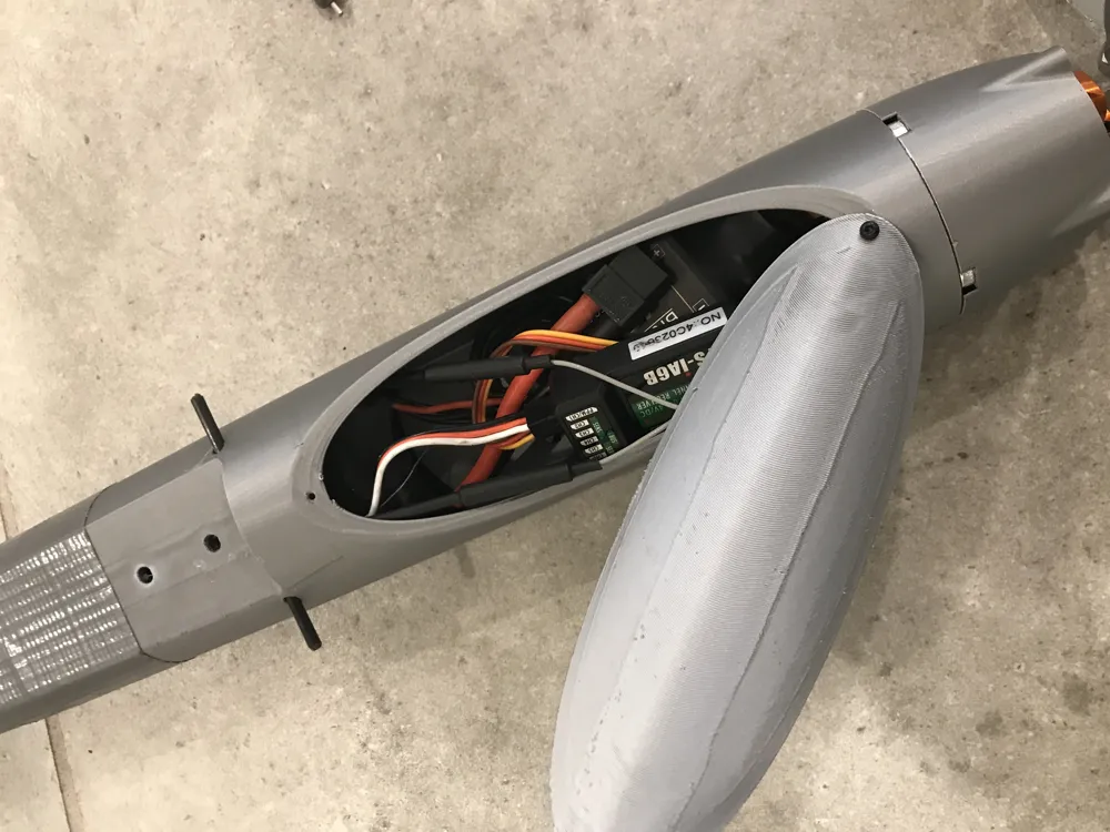
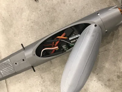
- Screw in the canopy with the two M2 screws. By only undoing one and swiveling the canopy, you can easily access the electronics inside.
Your fuselage is now done. You can now either figure out a way to attach wings and a tail you may have (or build them yourself first), or loosely follow what I have done. Please note that these are not comprehensive instructions.
For a the tail and wings, you will need the following:
- 3x servos (I recommend the Miuzei MG90S metal geared servos).
- 2x M4 screws
- 2x M3 screws
- 2x M2 screws
Servo extensions
Tail:
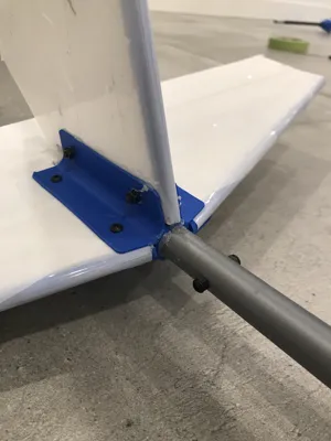
- Build a tail out of two layers of 4mm foam board using the tape-covering method (something like this).
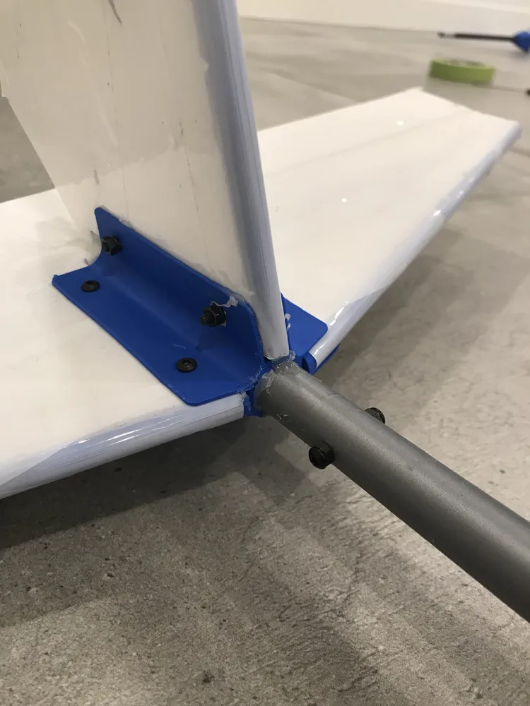
- Insert it (glue or screws) into the optional Tail connector in the files.
- Screw one of the servos in the mount below the connector with the M2 screws and install your pushrod system (note: the tail I have designed and use does not have a rudder).
- Run the servo wire into the rear of the connector and out the front (rectangle bit).
- Plug in the extension and feed the whole wiring through the fuselage into the front section (where the electronics go).
- Push the Tail connector into the rear of the fuselage, align the holes and secure it with the two M3 screws.
Wing:
- Construct an armin wing (like this) and insert the other two servos for your ailerons.
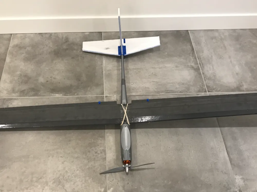
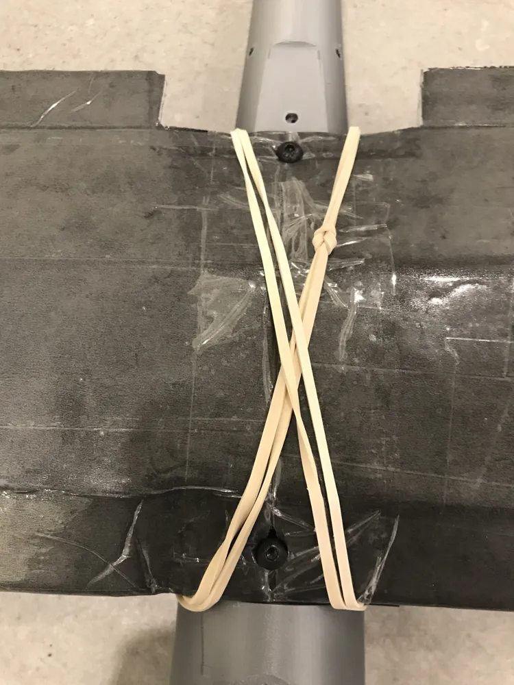
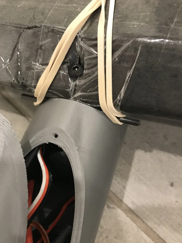
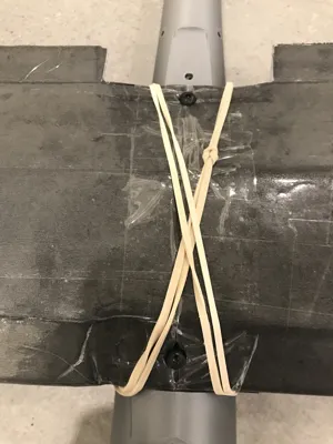
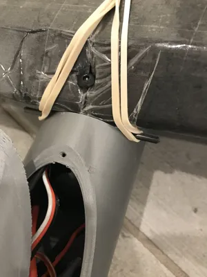
- To secure it to the fuselage, you can either use M4 screws to bolt it into the M4 nuts embedded in the fuselage, or use the rubber-band technique that is common in RC by passing 3mm rods (wood, metal, carbon, etc.) into the small holes in the sides of the fuselage to create anchors. Doing both is recommended, as the rubber bands take the load and the screws prevent any movement or misalignment (see pictures).
That's it! The goal of this fuselage is to create a starting point for your build, on which you can add your own wings and tail. Don't be afraid to experiment! You can of course print more parts or modify my design (hence why I have made the STL files available).
License

You shall not share, sub-license, sell, rent, host, transfer, or distribute in any way the digital or 3D printed versions of this object, nor any other derivative work of this object in its digital or physical format (including - but not limited to - remixes of this object, and hosting on other digital platforms). The objects may not be used without permission in any way whatsoever in which you charge money, or collect fees.


Comment & Rating (30)