
Mobile Box with Fold-Down Table




Print Profile(6)


Bill of Materials




Description
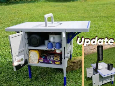
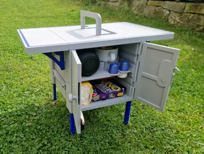
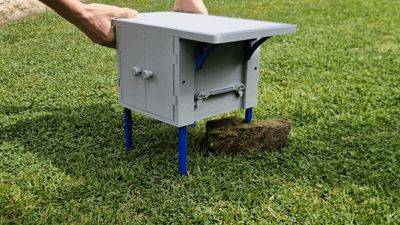
Mobile Box with Folding Table
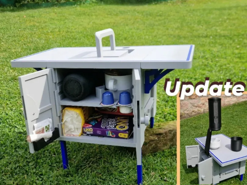
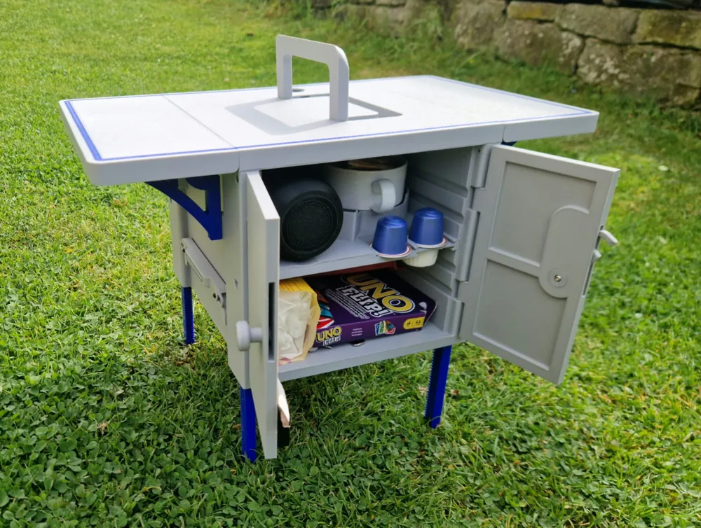
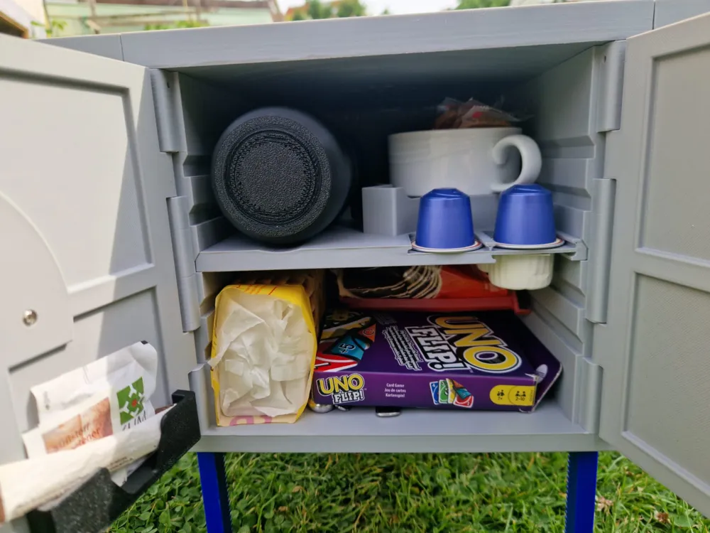
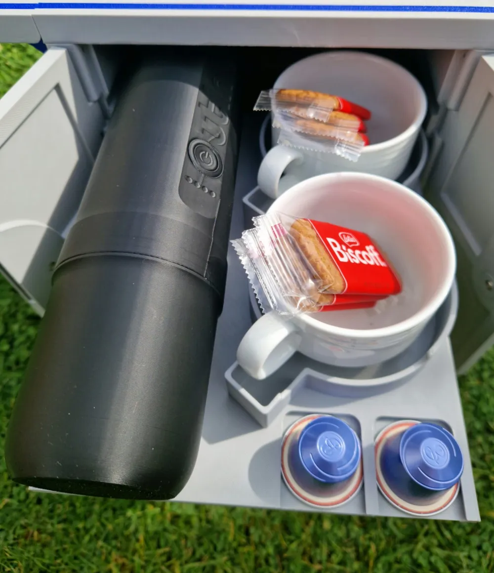
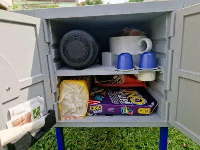
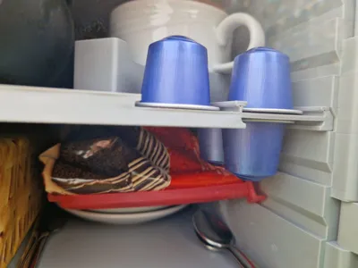
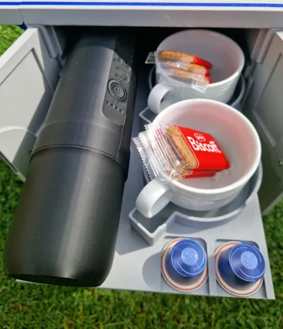
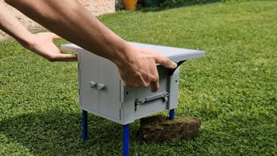
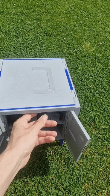
Everything shown in the pictures is fully stored inside the box
This box was specially developed for the “Coffee Goes Places – The Outing Challenge” competition. It is compact, robust, and functionally designed. All dimensions and components are directly matched to the competition model of the OUTIN coffee machine
It can also be used for any other purpose such as a beverage case, tool case, etc
All components were deliberately designed so that nothing needs to be stored loosely or separately.

Every function – whether folding table, holder, mechanism, or handle – is firmly integrated into the case and remains attached to the device even when open.
Everything can be unfolded, used, folded back, and stored securely – without individual parts being lost or forgotten.
Ideal for on the go, on uneven ground, or for frequent setup and dismantling

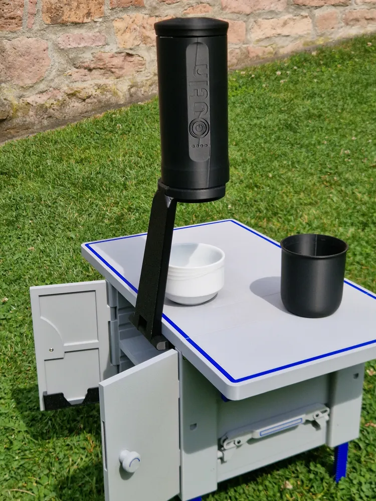
Update: v1.001.00
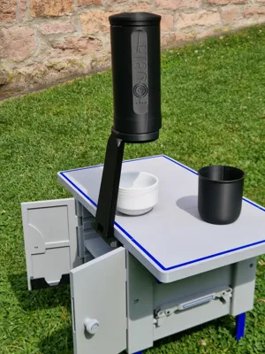
Extendable Holder for OUTIN Coffee Machine

This update adds a front-extendable, foldable holder to the box, into which the OutIn coffee machine can be securely placed. The holder is fully stowed inside and folds out when needed – stable, functional, and without external accessories
I made sure that:
- the part is cleanly printable
- the mechanism comes fully pre-assembled from the printer
the system securely supports the machine's weight (approx. 700g)
→ tested with 1kg weight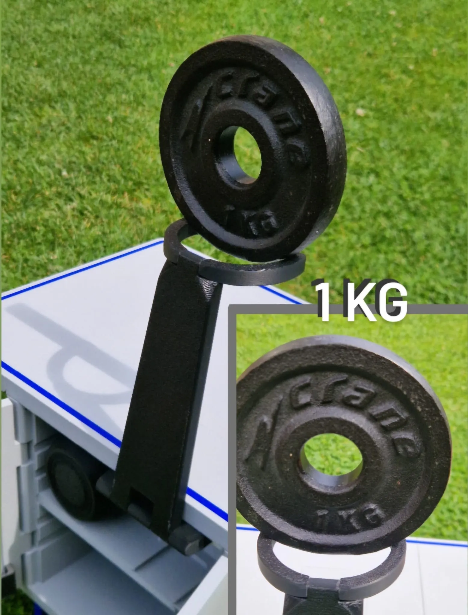
The holder is printed in one piece and is ready for immediate use after printing by gently moving it back and forth (carefully breaking the intended connections). No screws needed
Mounting Options:
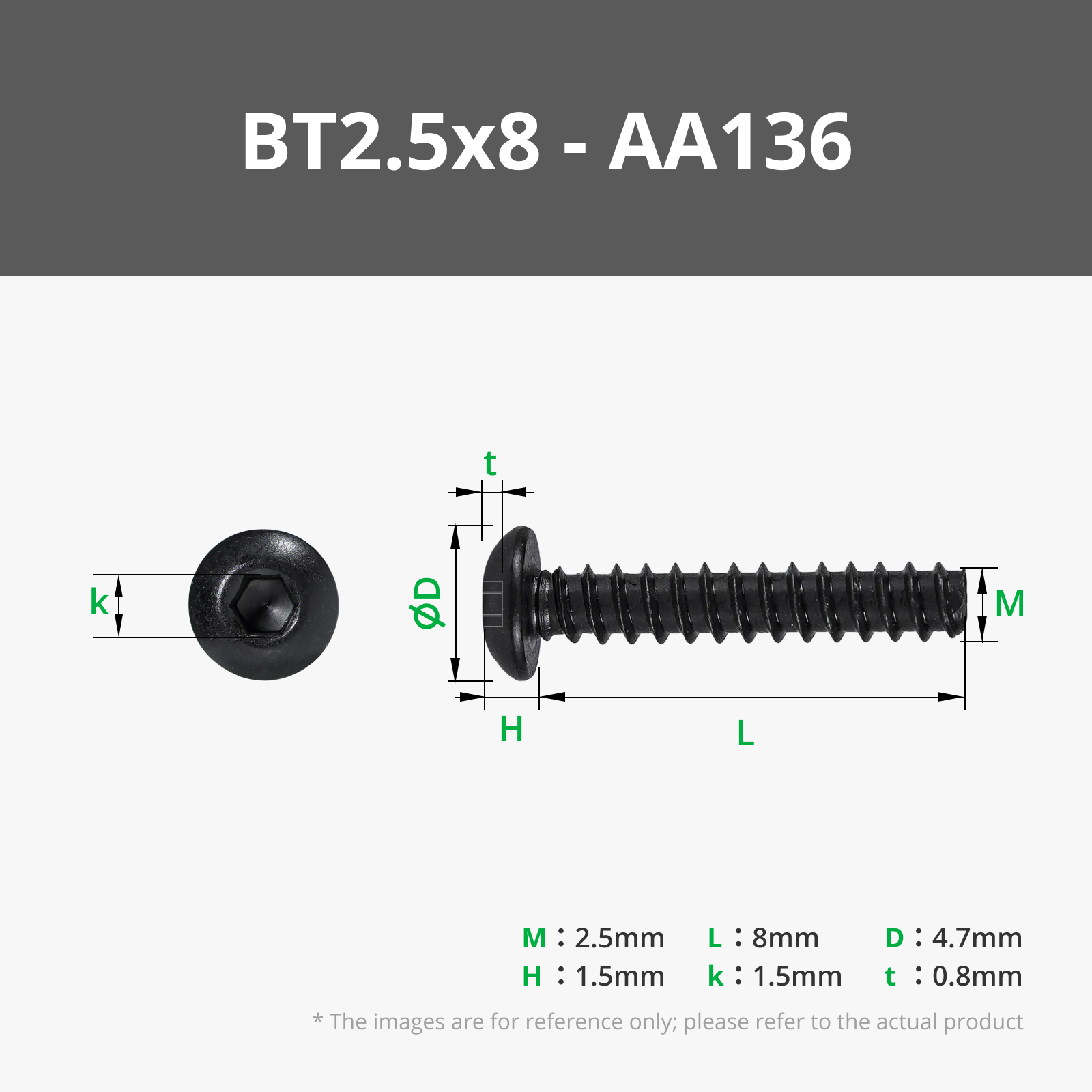
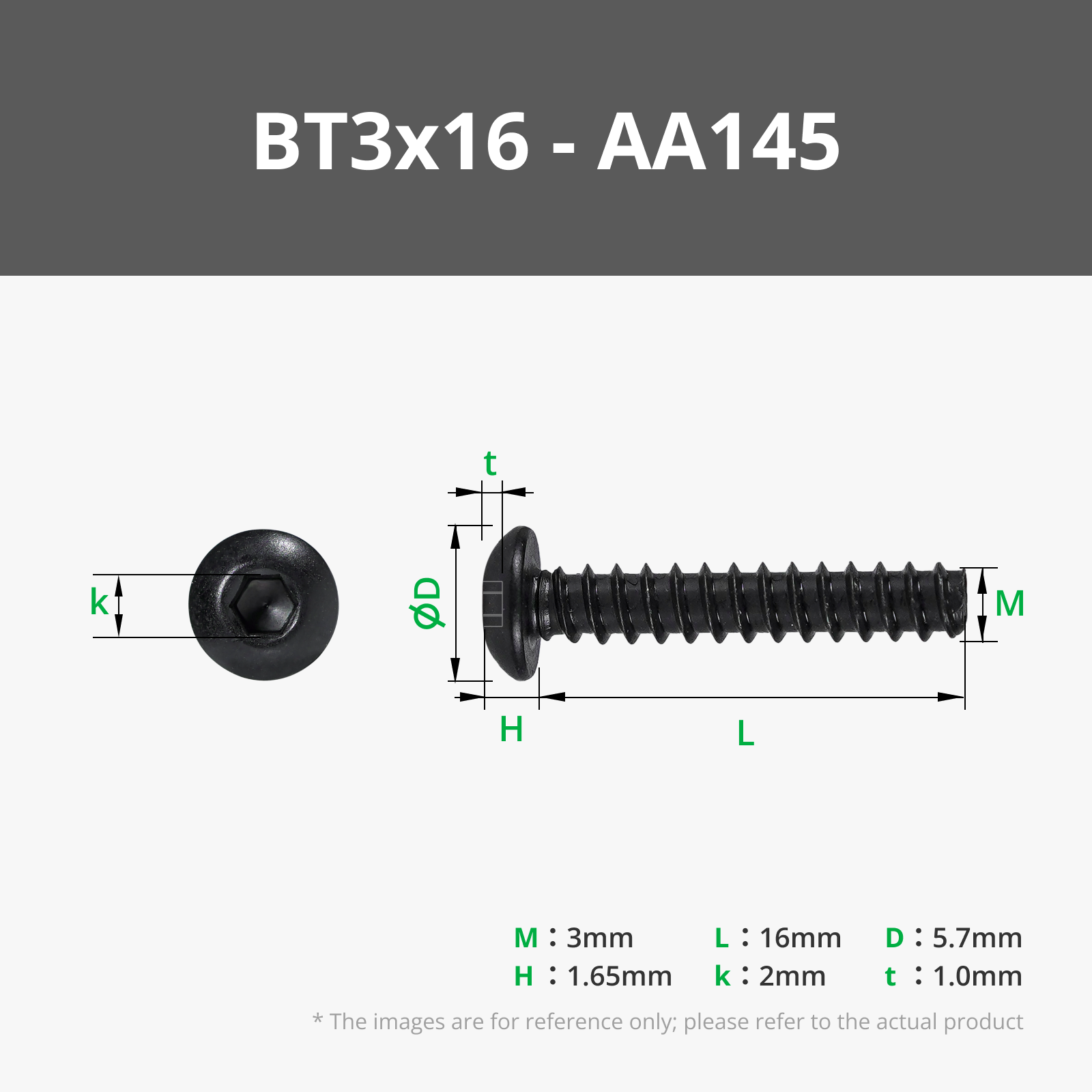
6 screws are needed for fastening. M3 x 16mm
- A new tabletop with matching drill holes can be printed
- Alternatively, the holder can also be mounted on an existing tabletop:
→ simply position it exactly flush with the closed door and screw the screws directly into the plastic
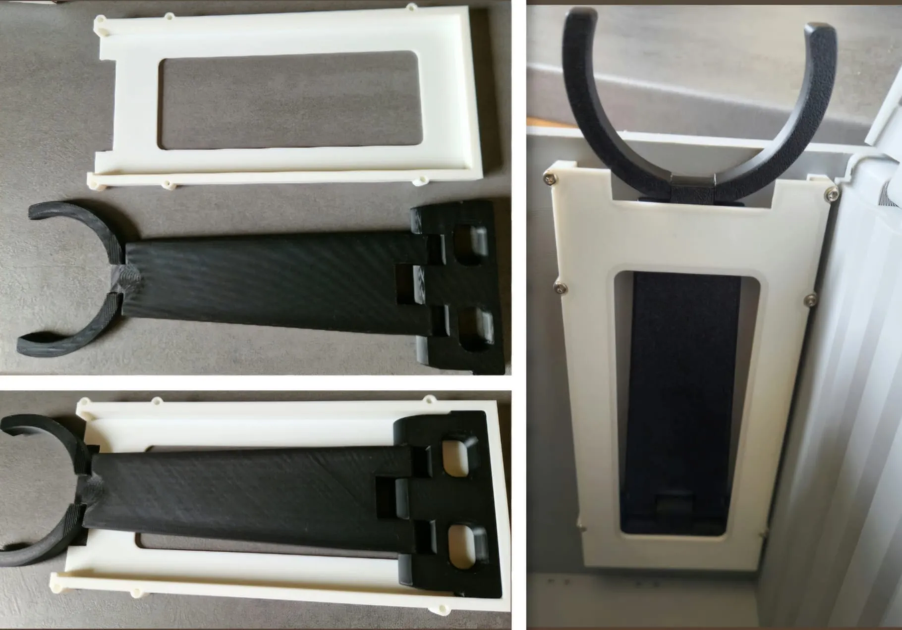
Print Files Overview:
- OutIn Holder
- Print Plate 1: OutIn Holder
- Print Plate 2: Holder
- Print Plate 3: Tabletop
Important:
The holder must not hit the door when folded out and should be mounted in such a way that it does not block the OUTIN coffee machine in the lower storage compartment.
Recommended position: right side, where the cups are stored. Before mounting, check that the door closes easily with the holder closed
Model Description:
Overall Dimensions:

Completely assembled: 250x267x200mm
Completely unfolded: 420x267x395mm
Complete Table: 420x250mm
Max. Leg Length: 140mm
Construction & Use
- Side folding table surfaces
- Height-adjustable feet for stable standing on uneven terrain
- Front door with rotary lock, multiple floor heights selectable
Three interchangeable floor variants provided by me (incl. smooth universal floor) – your own variants can be created based on the supplied drawing
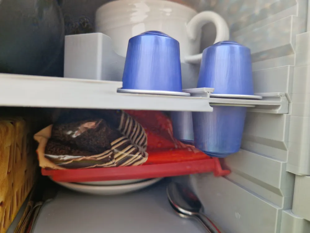
- Floor 1: Holder for OutIn coffee machine, 2 cup slots, 4 slots for milk pods or coffee pods
- Floor 2: Same as Floor 1, but with 6 slots for milk pods or coffee pods
- Floor 3 (smooth variant): A universal, flat base plate – already included as a finished print file
- Optional adhesive sugar holder

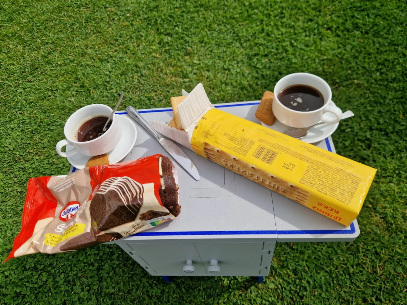
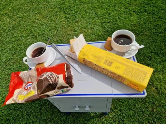
The box also offers enough storage space for snacks, water, cake, cards, etc. – ideal for coffee on the go, picnics, or small outdoor sessions
Technical Details
- Side table tops adjustable with screws in the angle brackets
- Recessed handle with rocker button, no visible recesses
- Magnetic snap-in function for locking the table sides – pay attention to correct polarity during installation
- The tensioner system is deliberately slightly raised when the feet are retracted – serving as a visual indication that the feet are fully retracted
Maintenance, Replacement & Repairability
All parts of the box are designed so that they can be individually removed and replaced without damaging or destroying other components
- All connecting pins are provided with holes on both sides. This allows them to be pulled out with a simple screw when installed
- This allows for quick replacement of defective parts, e.g., after mechanical wear or printing errors – without a complete reprint
- The instructions contain clear indications of which parts need to be post-processed, deburred, or checked for smooth movement before final assembly
This system is therefore designed to be particularly durable, easy to maintain, and sustainable
Cup Compatibility
- Tested with cups up to 80mm in diameter
- Maximum cup width with side-protruding handle (24mm deep, 19mm wide) up to 89mm total diameter
- When using the middle level, a cup up to 80mm in height fits
Questions & Support:
- If you have questions, something isn't working, or you have change requests, if something doesn't fit, please contact me – I'll be happy to help you further. I strive to help quickly and solution-oriented
Material & Printing Notes
I printed the entire model from PETG. I noticed warping on larger components. I was able to reduce this somewhat through adjustments, but generally:
👉 Anyone else printing with PETG should research warping beforehand so that no large parts are lost or become unusable
The model was printed by me in multi-color with an AMS system. Those who do not own an AMS can easily print it in single color – the color distribution is purely optional. The chosen colors in the model are only suggestions, any combination is possible
Some components require support structures. These should be carefully removed after printing and the contact surfaces smoothed if necessary
Boost Me (for free)
If you like the model, I appreciate a boost or a rating.
This helps make more high-quality designs possible. Thank you!
Print Files Overview:
- Main Body
Print Plate 1: Main Part
Large Parts
- Print Plate 1: Side Table Tops
- Print Plate 2: Door
- Print Plate 3: Angle for Side Plate
- Print Plate 4: Lid Table
- Print Plate 5: Standard Base
Small Parts
- Print Plate 1: Leg Tensioner, Tensioner Pin, Tensioner Stop, Cover
- Print Plate 2: Rocker, Rocker Pin, Rocker Cover, Handle Cover
- Print Plate 3: Door Knob, Latch, Door Knob Washer
- Print Plate 4: Sides, Angles, Door, Handle, Lid Pin
- Print Plate 5: Side Hinges
- Print Plate 6: Handle
- Print Plate 7: Leg Tensioner Spacer Pin
- Print Plate 8: Tensioner Pull Part
- Print Plate 9: Legs
- Base OutIn
- Print Plate 1: Base, 2 Cups, 4 Slots
Print Plate 2: Base, 2 Cups, 6 Slots
- Sugar Holder
Print Plate 1: Sugar Holder
Assembly Instructions:
General Notes before Assembly:
- All pins that cannot be removed by pushing through have a hole on both sides. This allows them to be easily pulled out with a screw when installed. This enables repairs of individual parts and helps save material
- All moving components must be checked for their function before final assembly. They should move easily and cleanly
- Elements such as the carrying handle may hook slightly so that they remain in a desired position
- Other parts such as angles or tensioners should move very easily, ideally by gravity alone. If this is not the case, the relevant contact or bearing surfaces must be deburred or reworked
- Carefully check the magnet alignment before gluing to ensure it fits.
Step 1: Assembly of the Main Body with Tensioner Mechanism
Components: Main body, spring, tensioner for the feet, pin, stop for the tensioner, cover
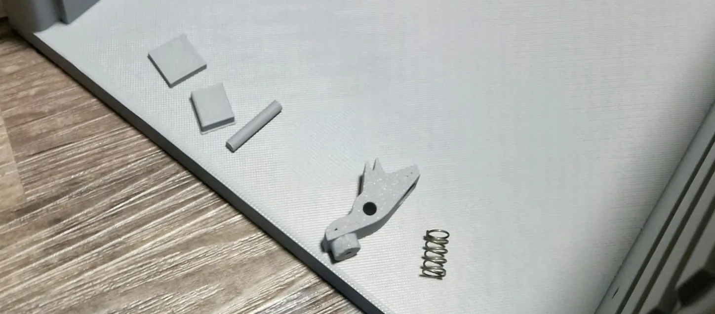
Insert the tensioner with the spring (7x12x0.5mm) into the main part from below
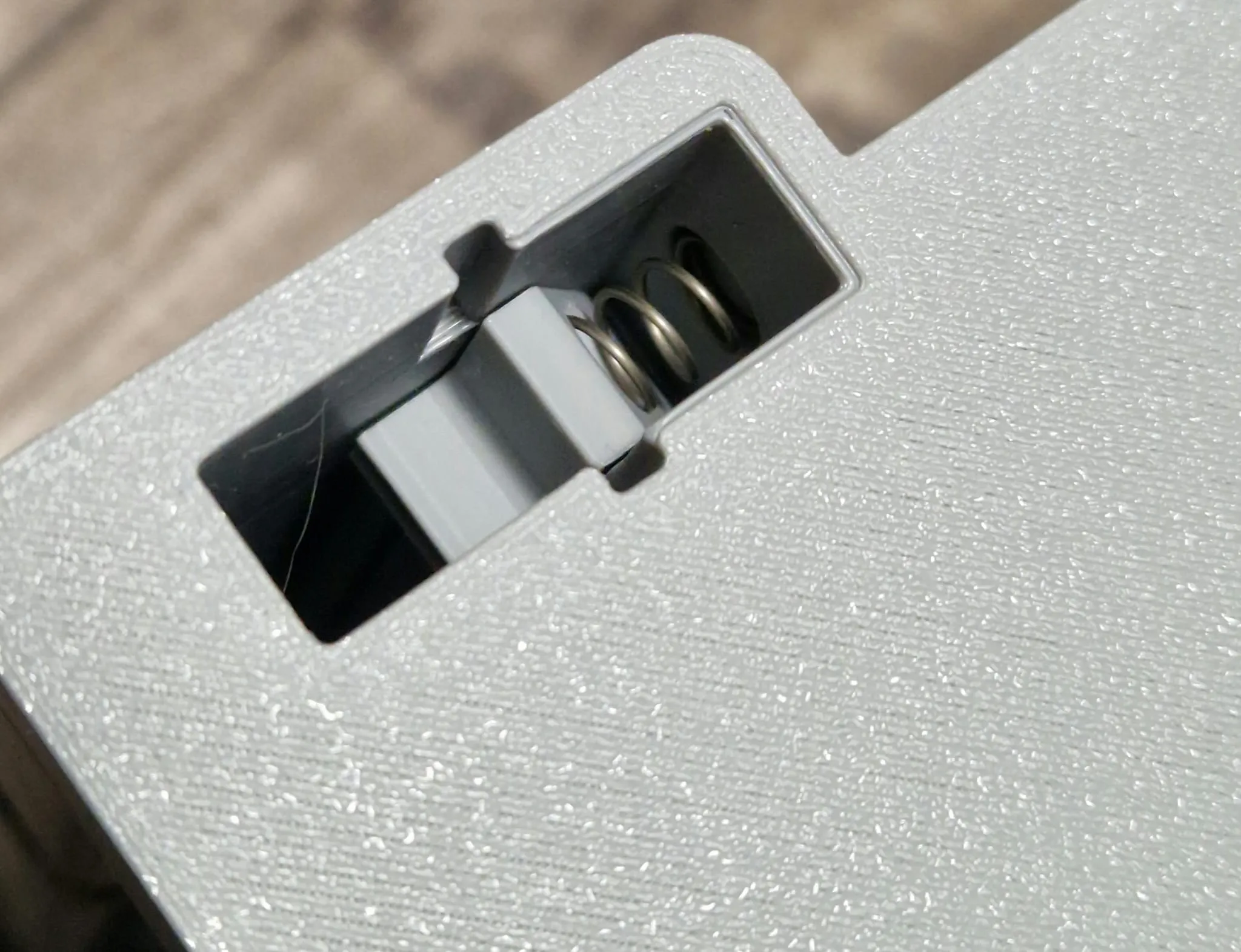
Insert the stop/cover (with the notch pointing upwards towards the spring)

Gently move the tensioner with pliers so that the hole is clear and push in the pin
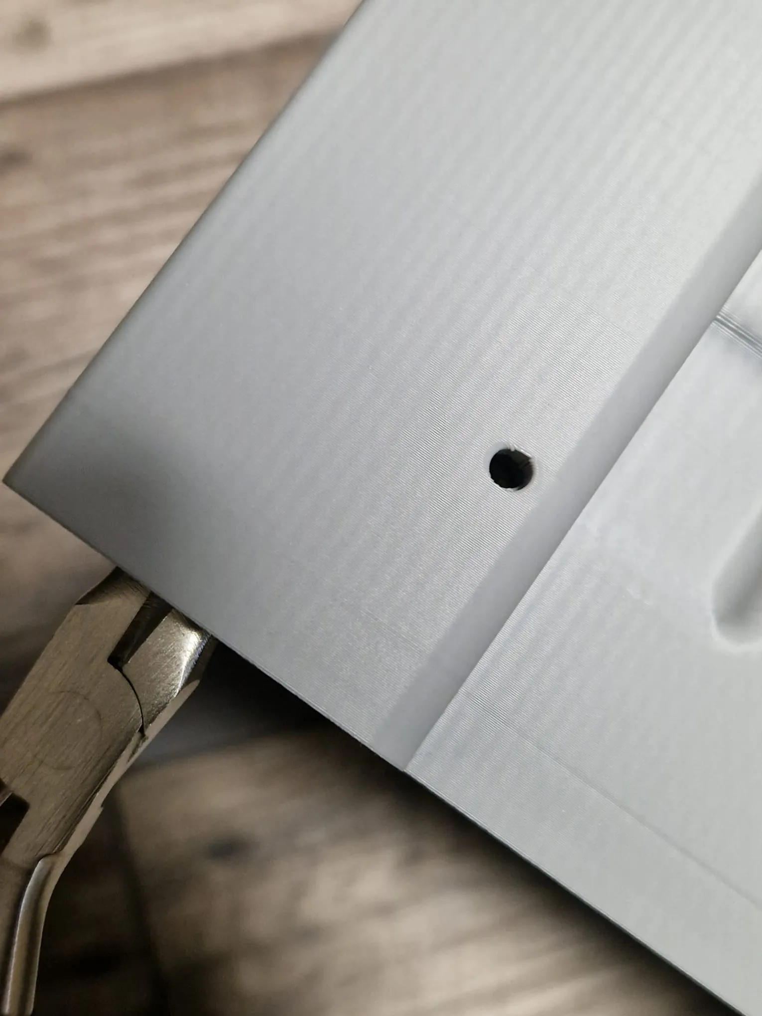
Check function: Tensioner should only have the spring's resistance and otherwise move easily
Step 2: Repeat for all four feet
- Repeat the steps as above for all three other corners
- Spring orientation must match the bore each time
Step 3: Assemble Pull/Push Elements
Components: Pull element, spacer, pin (round/square), printed washer
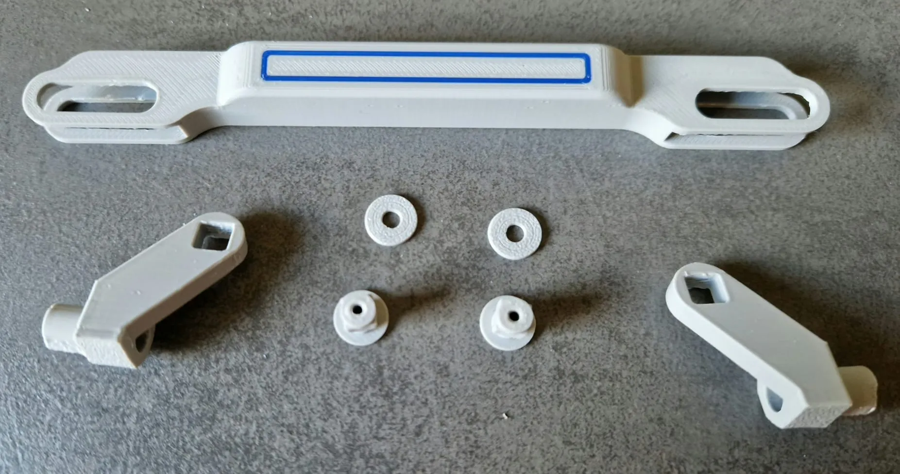
- Insert the spacer into the pull element from below
Guide the pin through the parts, flush at the back, almost flush at the front, slightly protruding
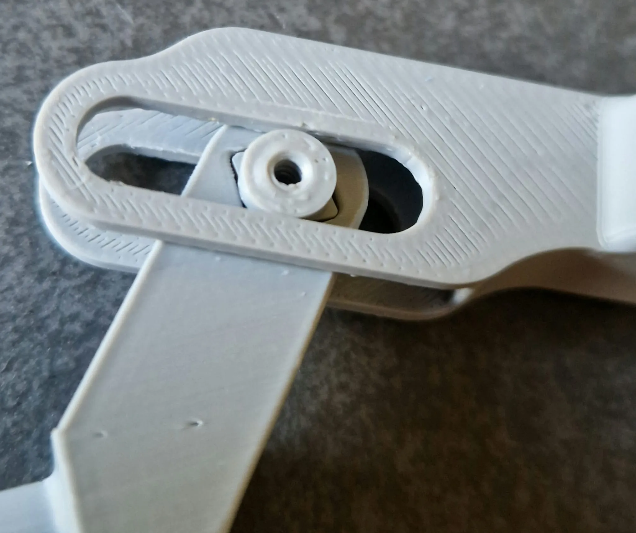
Insert and screw in screw M2.5\2.6 x 8mm + washer
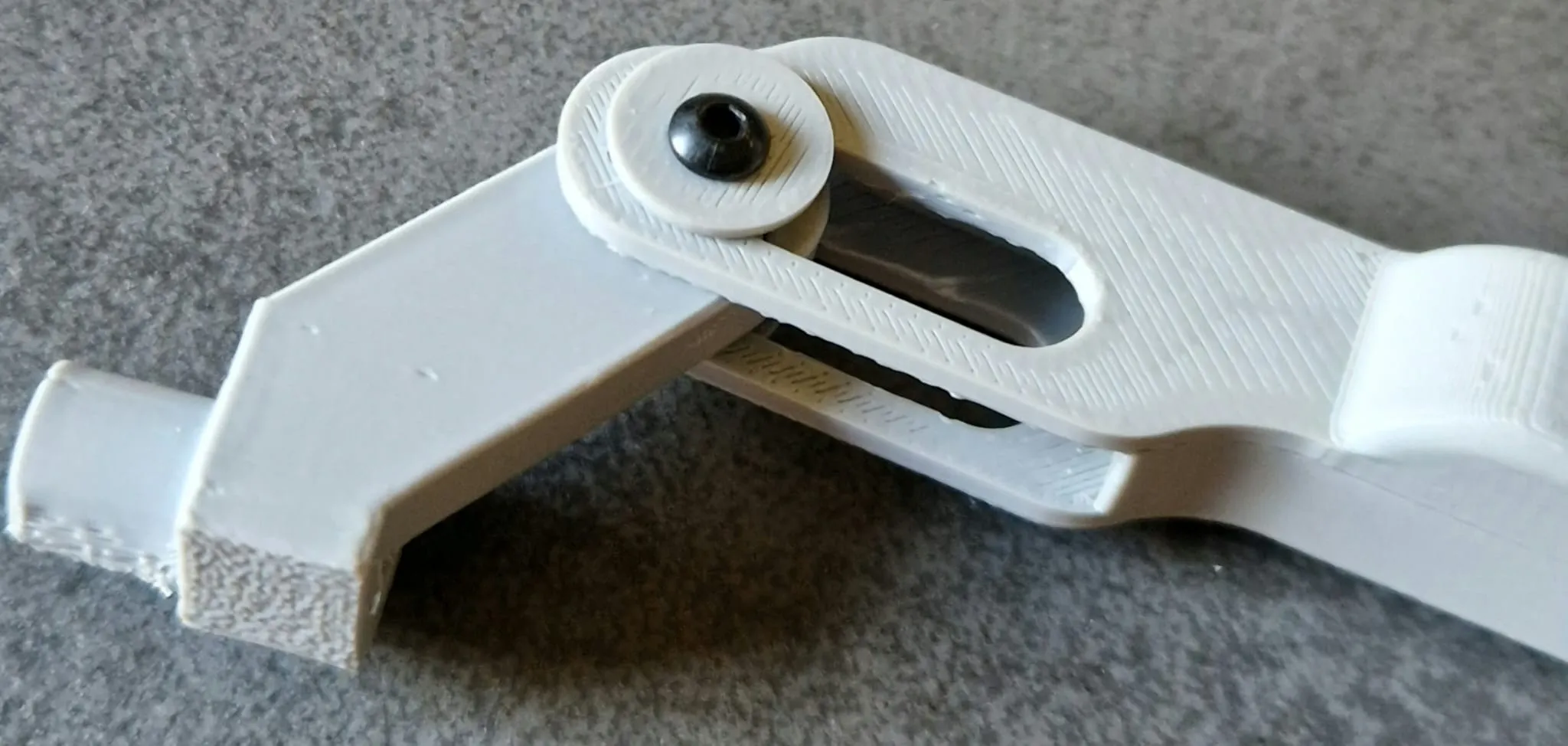
- Repeat on the other side, mirrored
Place the pull element on the main body and screw it in on the right and left with M3 x 18mm. Then assemble the other side identically
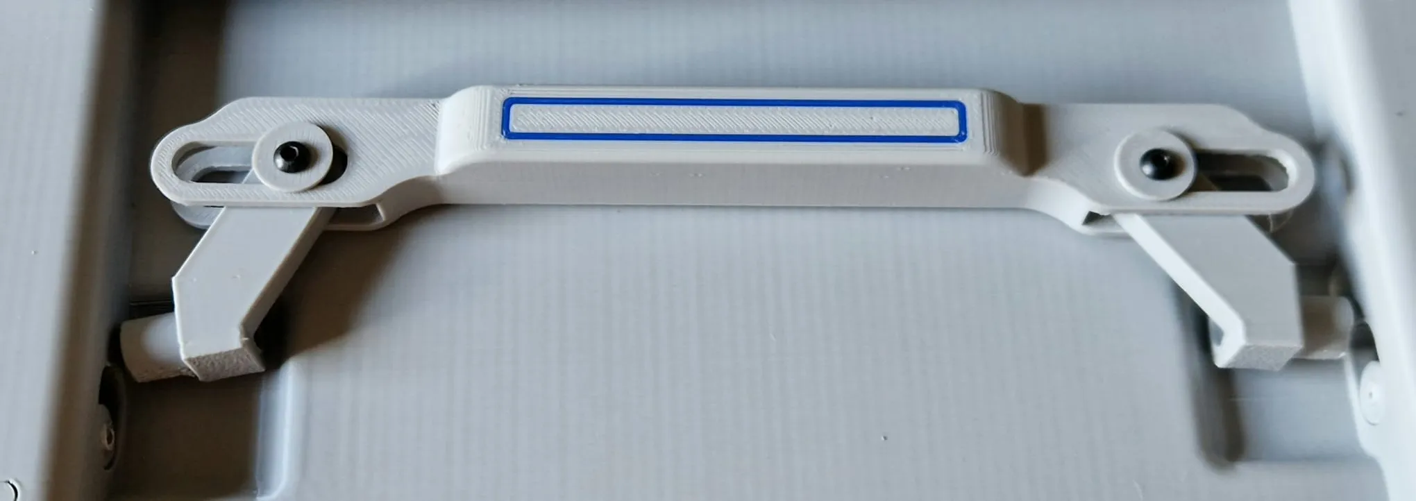
Step 4: Foot Assembly
Insert feet from above (ribbing points inward)
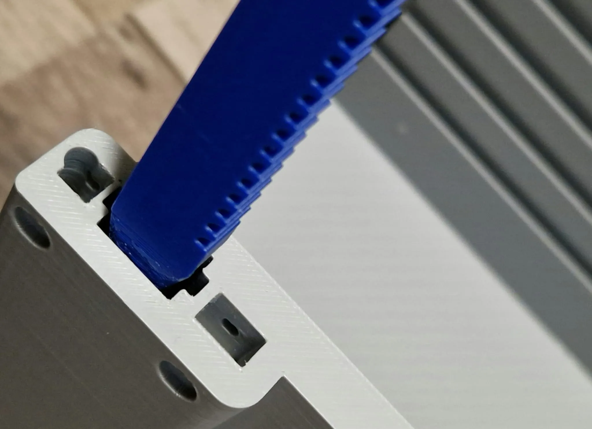
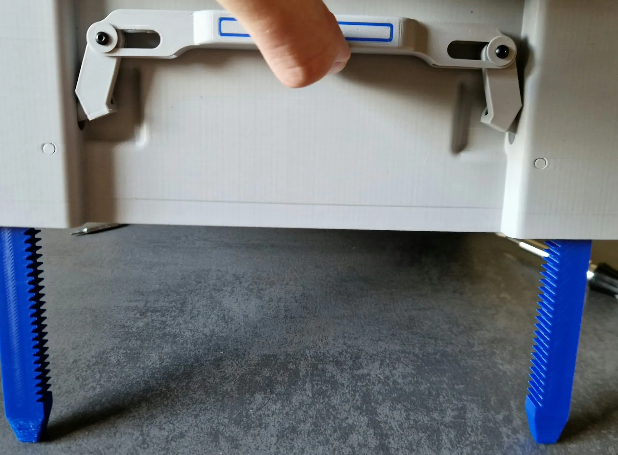
Test: Release tensioner via pull elements, feet must retract completely
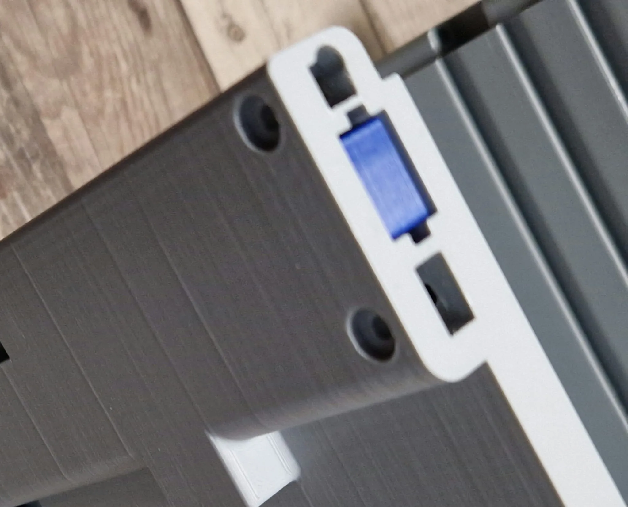
- If not possible: Rework
Function check: Lift main body, pull tensioning elements, feet must be able to fall out freely
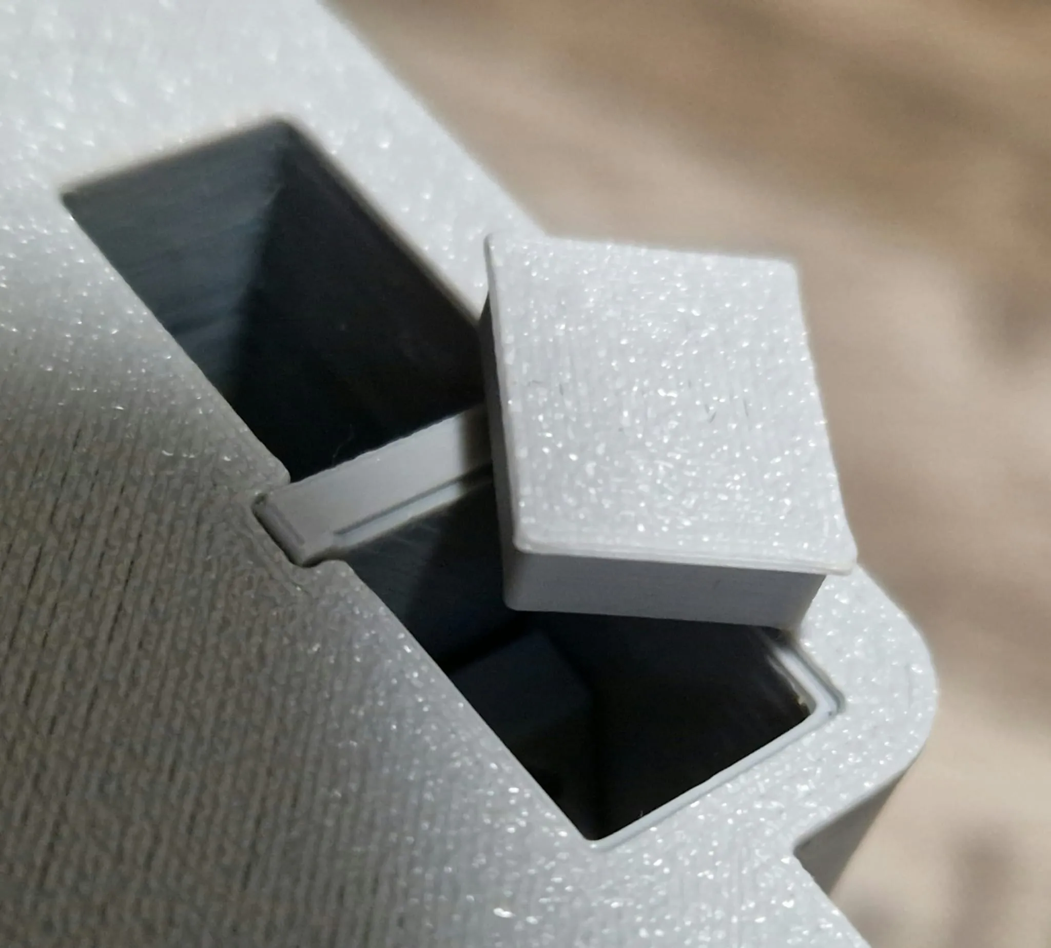
Press covers from below. (The leg is missing in the picture)
Step 5: Door Assembly
Left door: Insert knob without latch, screw in from behind M3 x 10mm (M2.6\2.5 should also work)
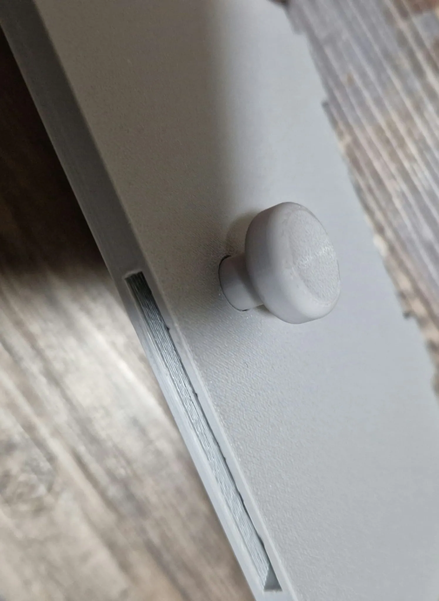
- Right door: Insert latch, snap knob with square
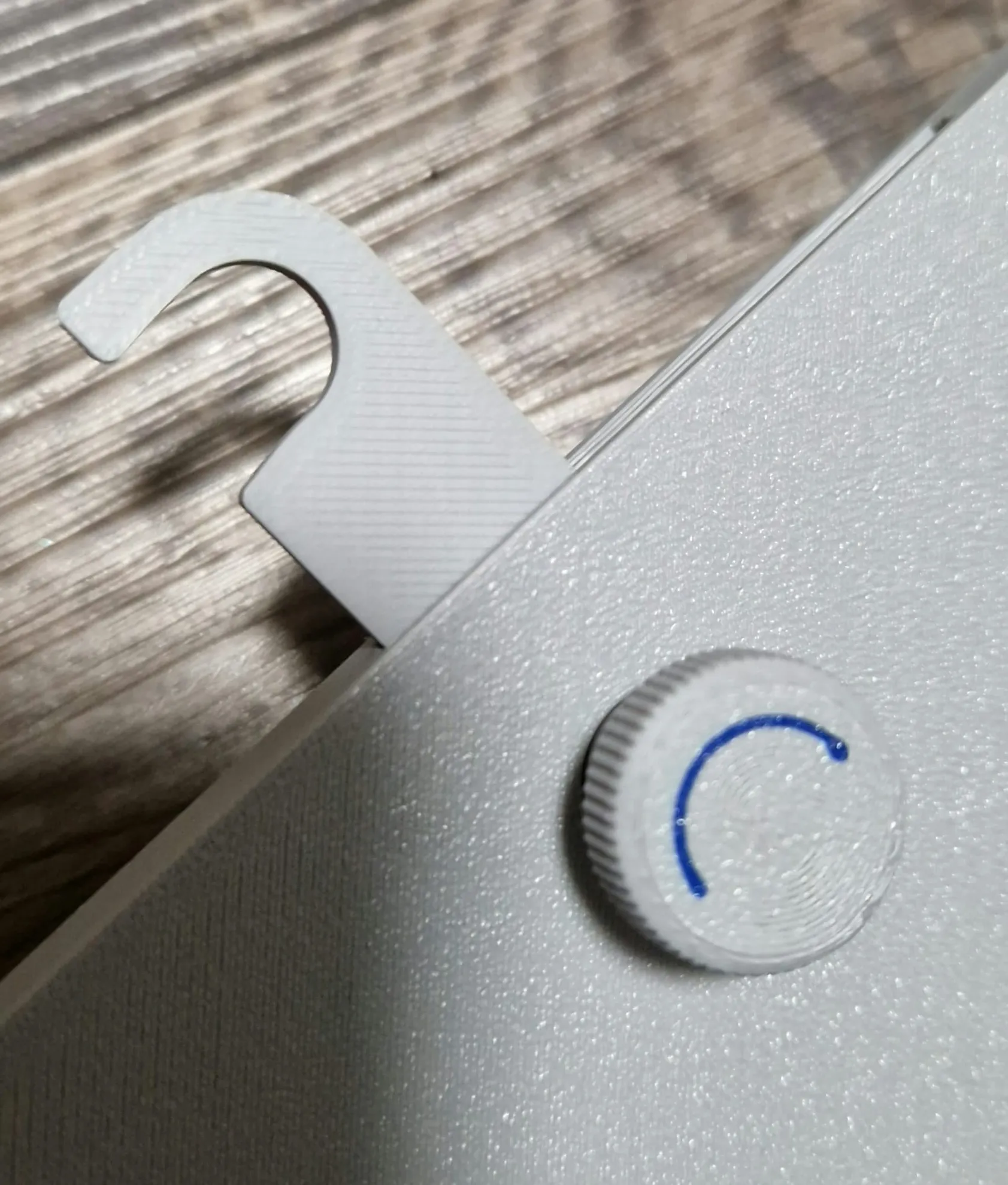
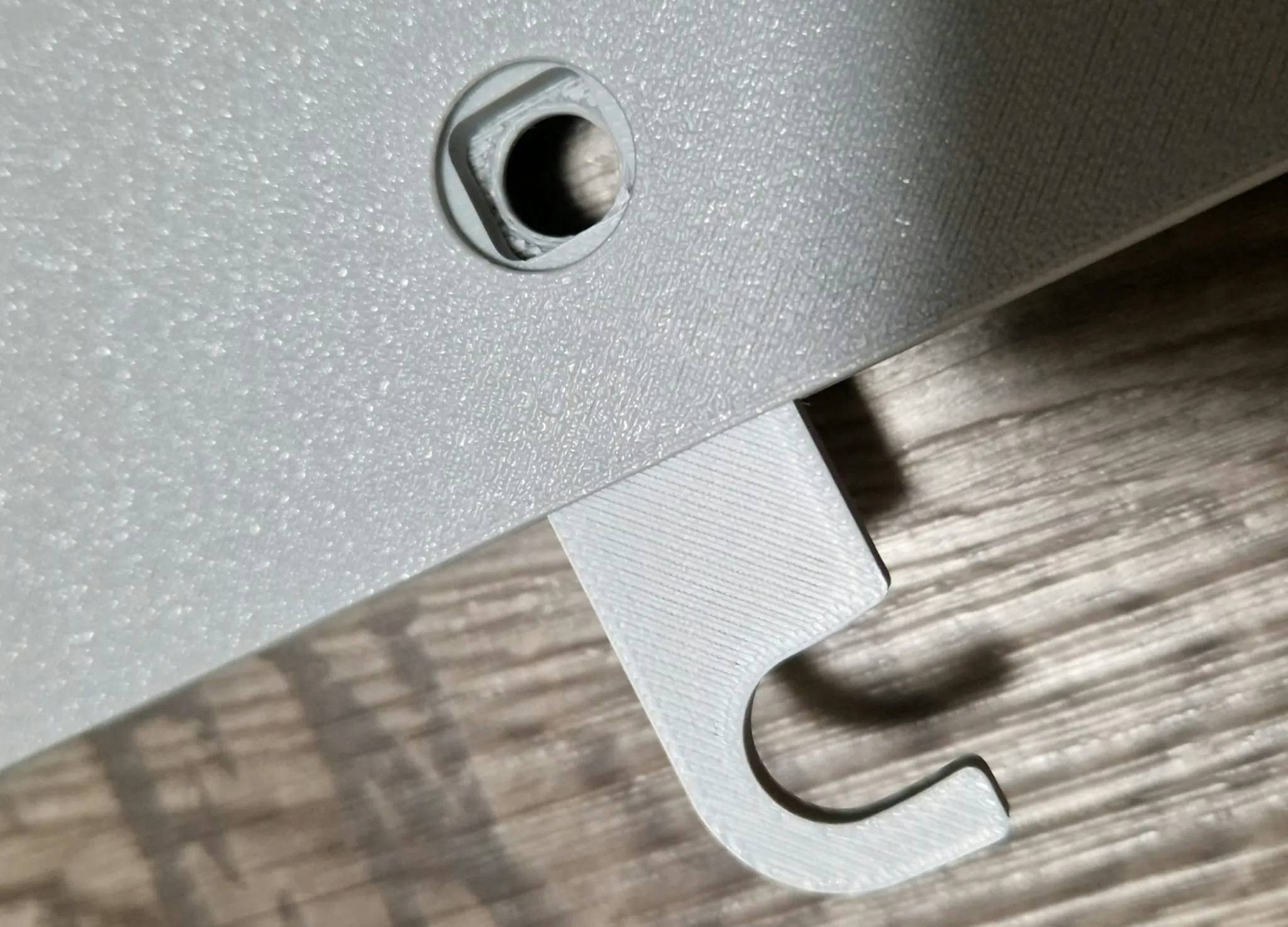
- Pay attention to the marking (arrow): it should be as shown in the right picture
- Next, screw the end cap of the latch knob from behind M3 x 10mm (M2.6\2.5 should also work)
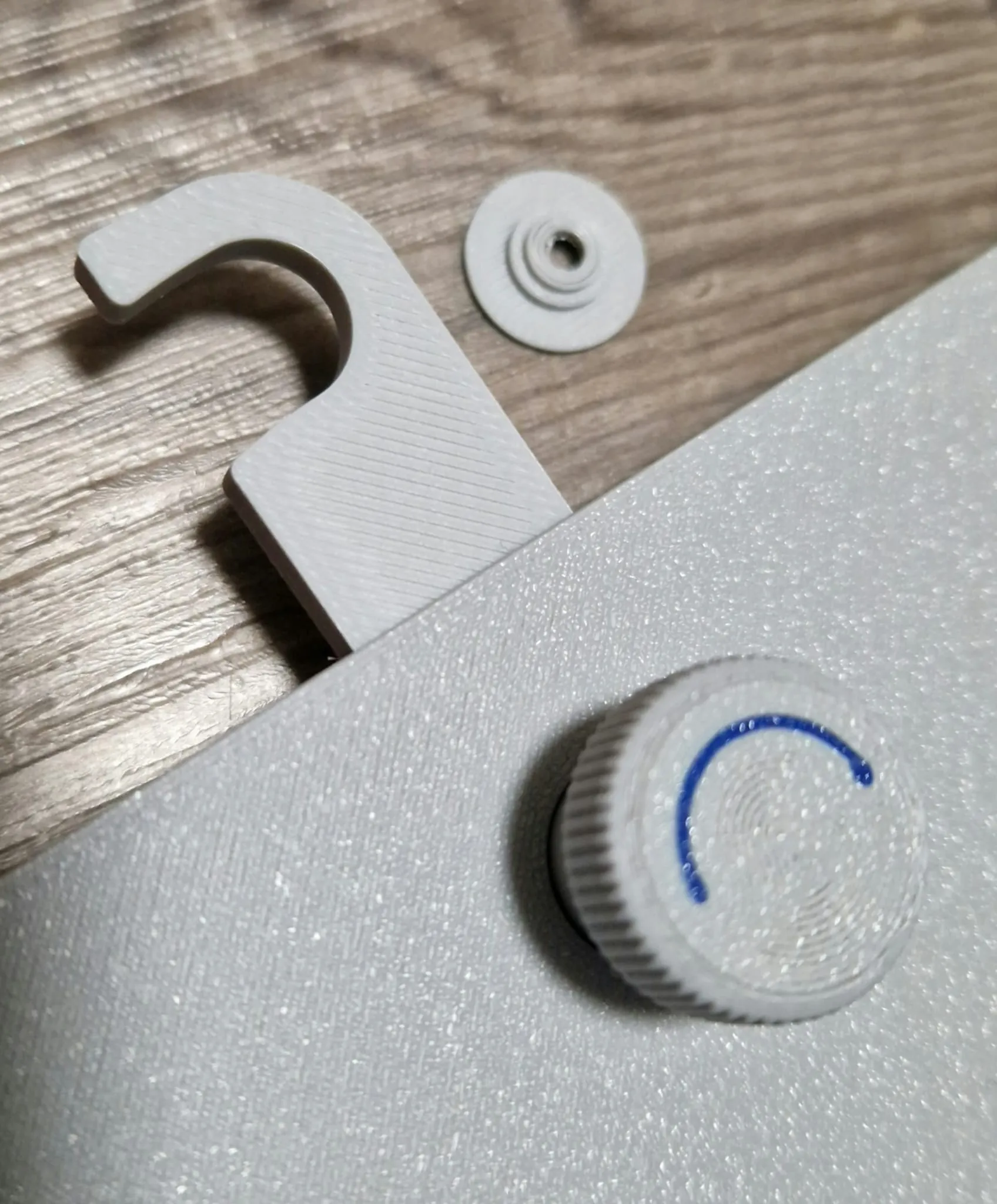
Insert doors into main body, push bolts in from above. Make sure to press them down as shown on the right until round
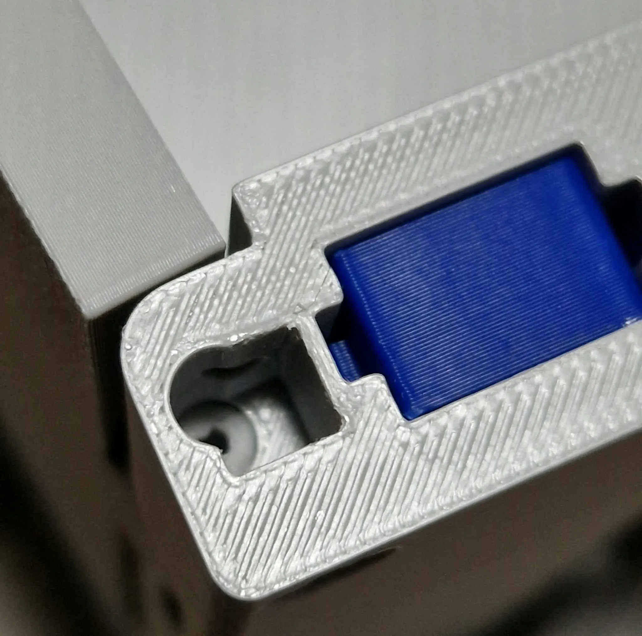
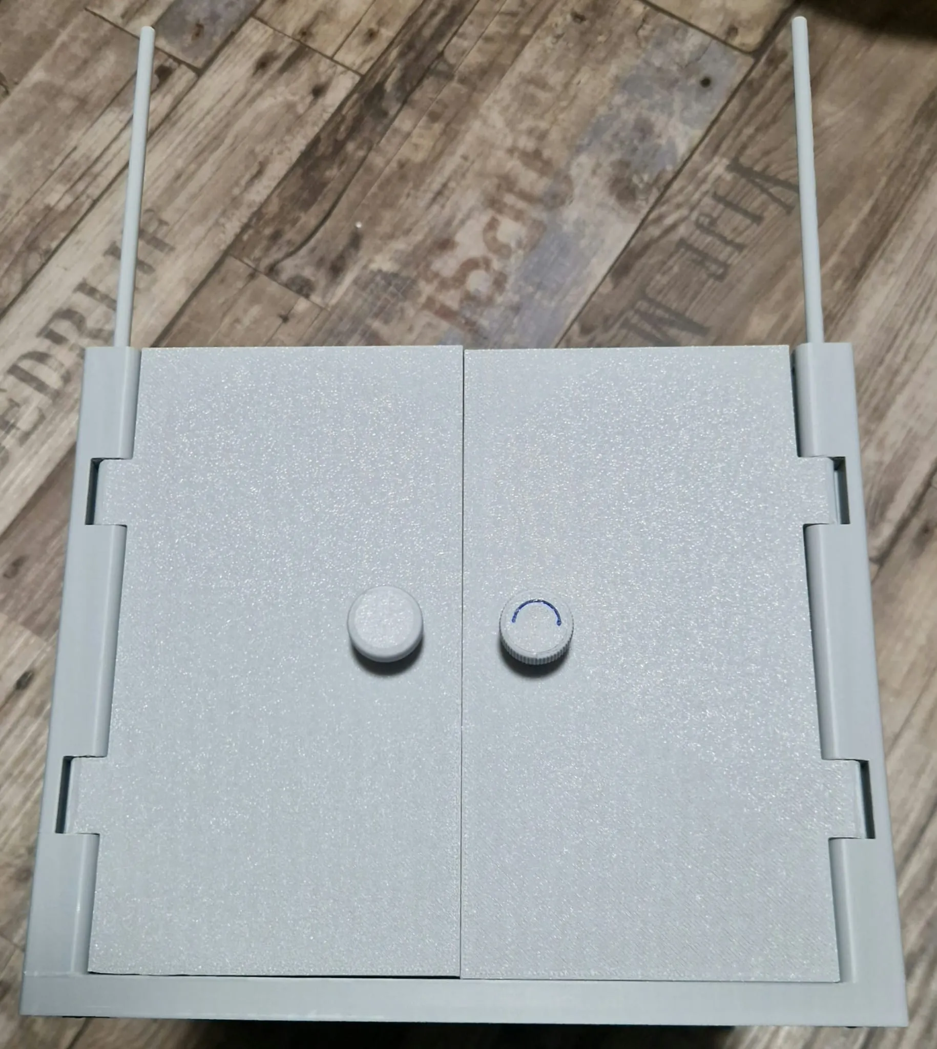
Step 6: Prepare Tabletop
- Insert handle into lid from above, push bolt in from below, right as well as left
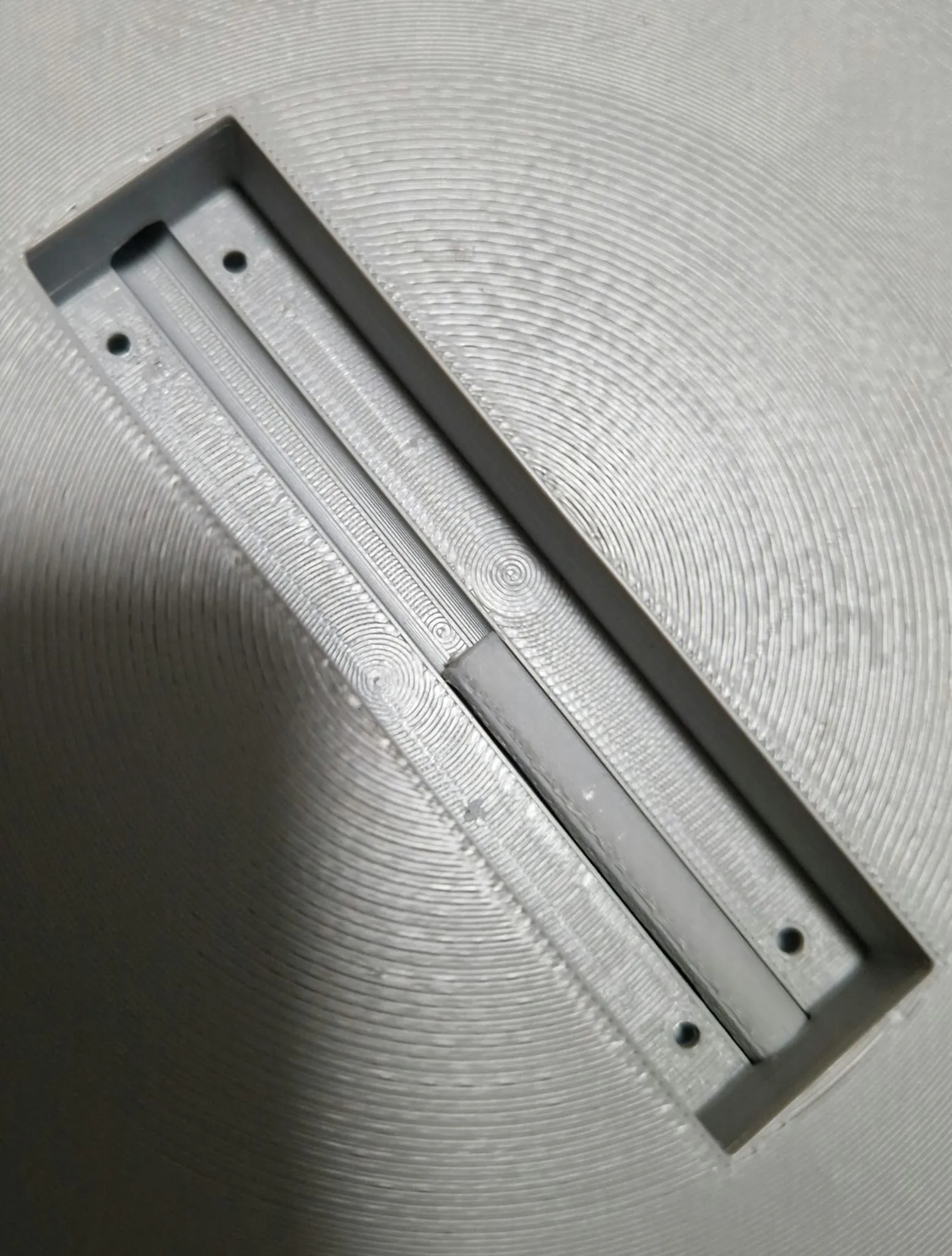
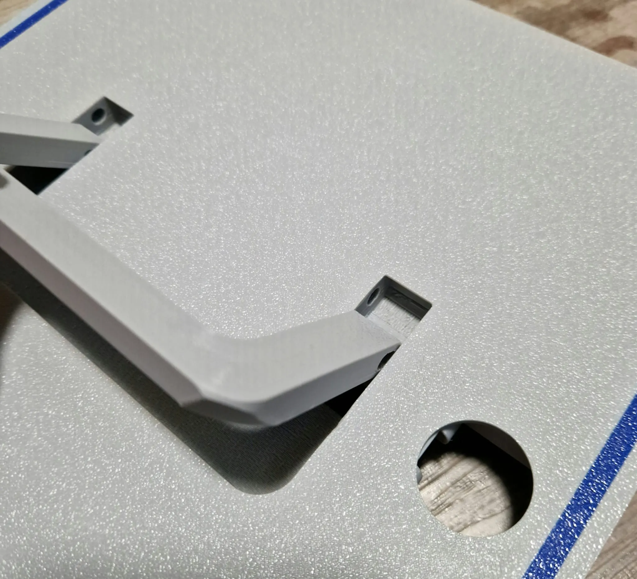
- Rocker button: Insert pin (as in the picture), then lift the plate and press out the handle, then you can guide the rocker with the thin side into the plate. Afterwards, the bolt should insert into its designated place. As shown in the next picture, the rocker should then lie straight inside. Then you can place the cover, large area at the back at the round part, and then screw it down M3 x 10mm or M2.6\2.5 x 8mm
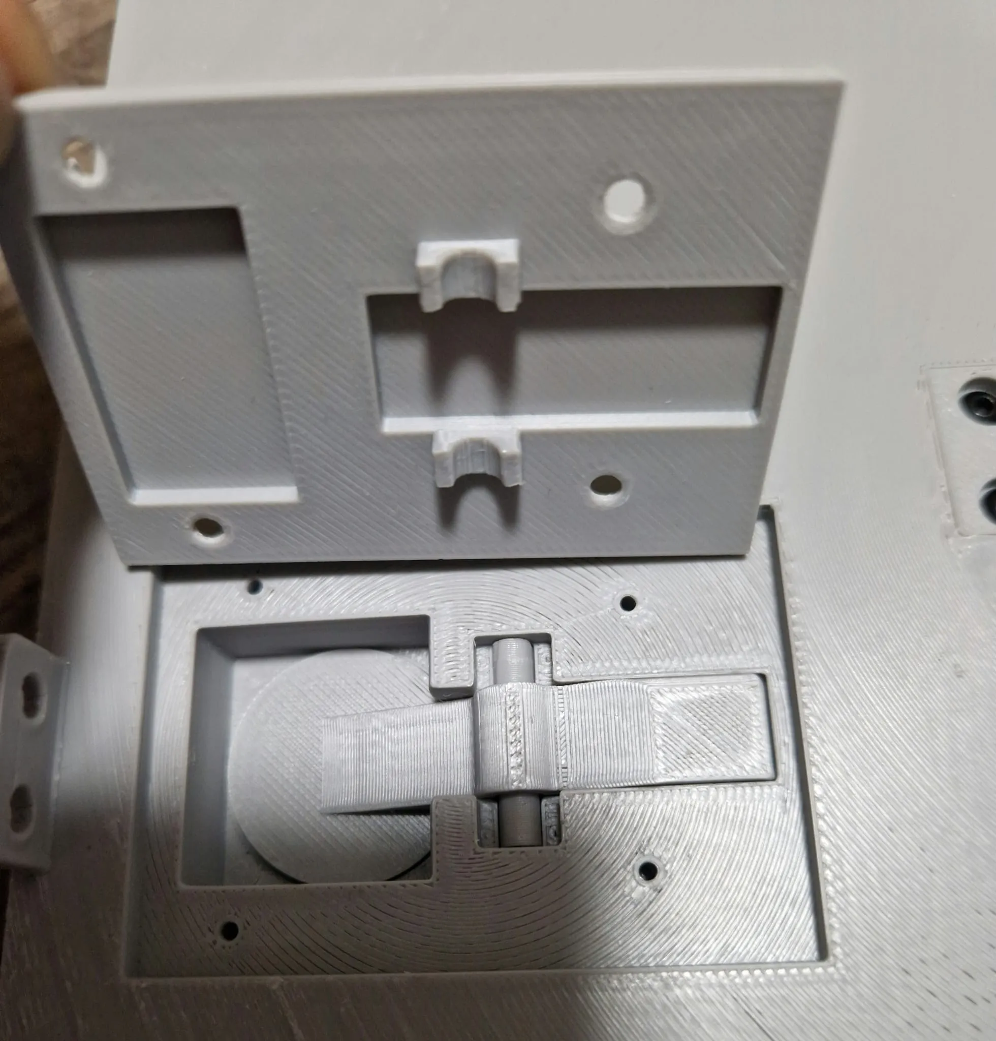
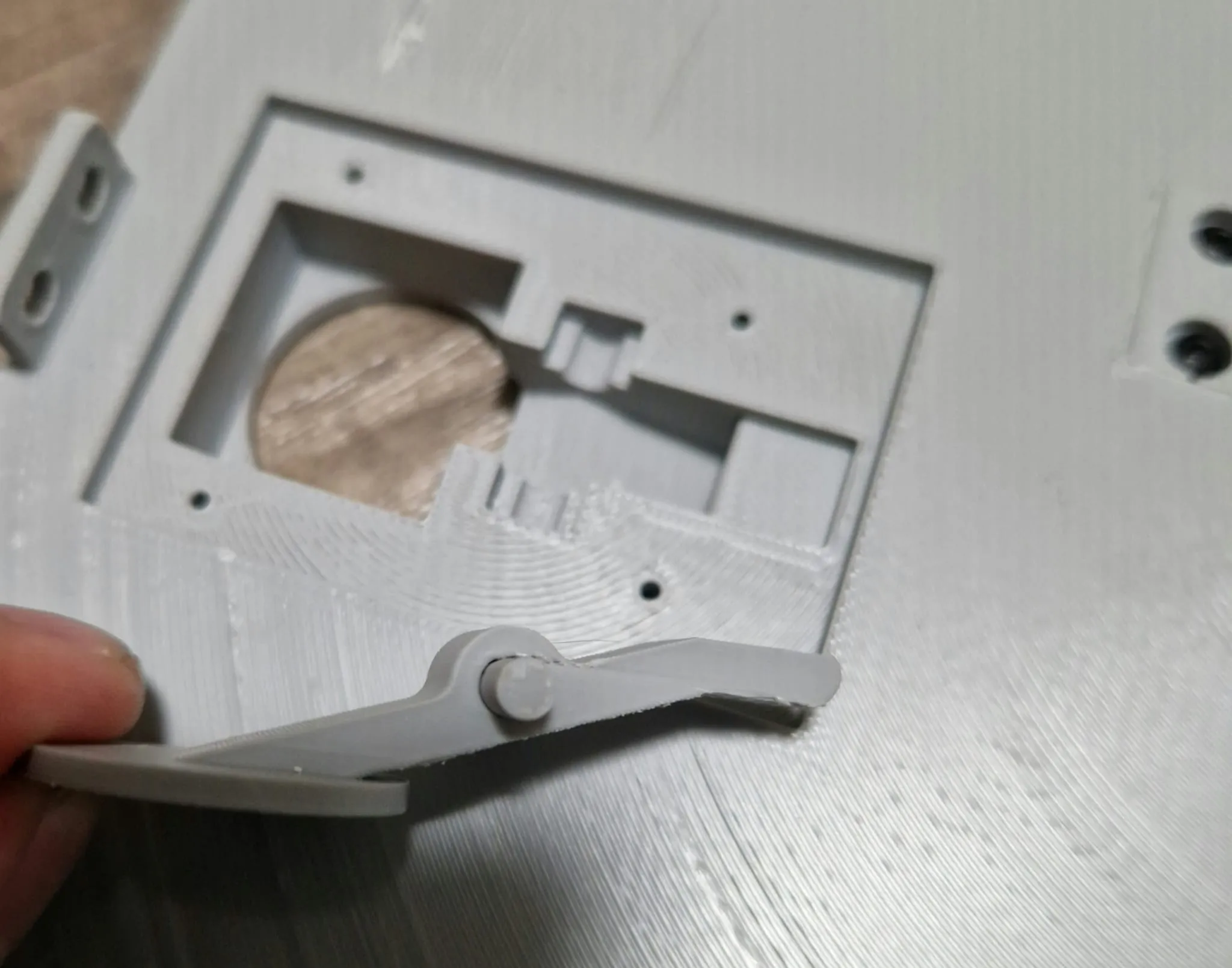
Insert the middle cover (turn if necessary, if screws do not fit). Screw in M3 x 10mm or M2.6\2.5 x 8mm
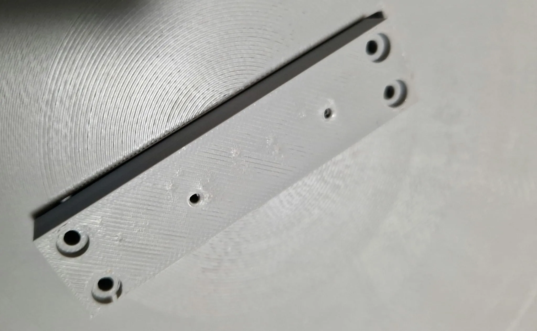
Press in the hinge element as shown in the picture, make sure it is inserted correctly, and repeat this for the other 3 positions. Afterwards, fasten all with 2 screws M3 x 10\12mm
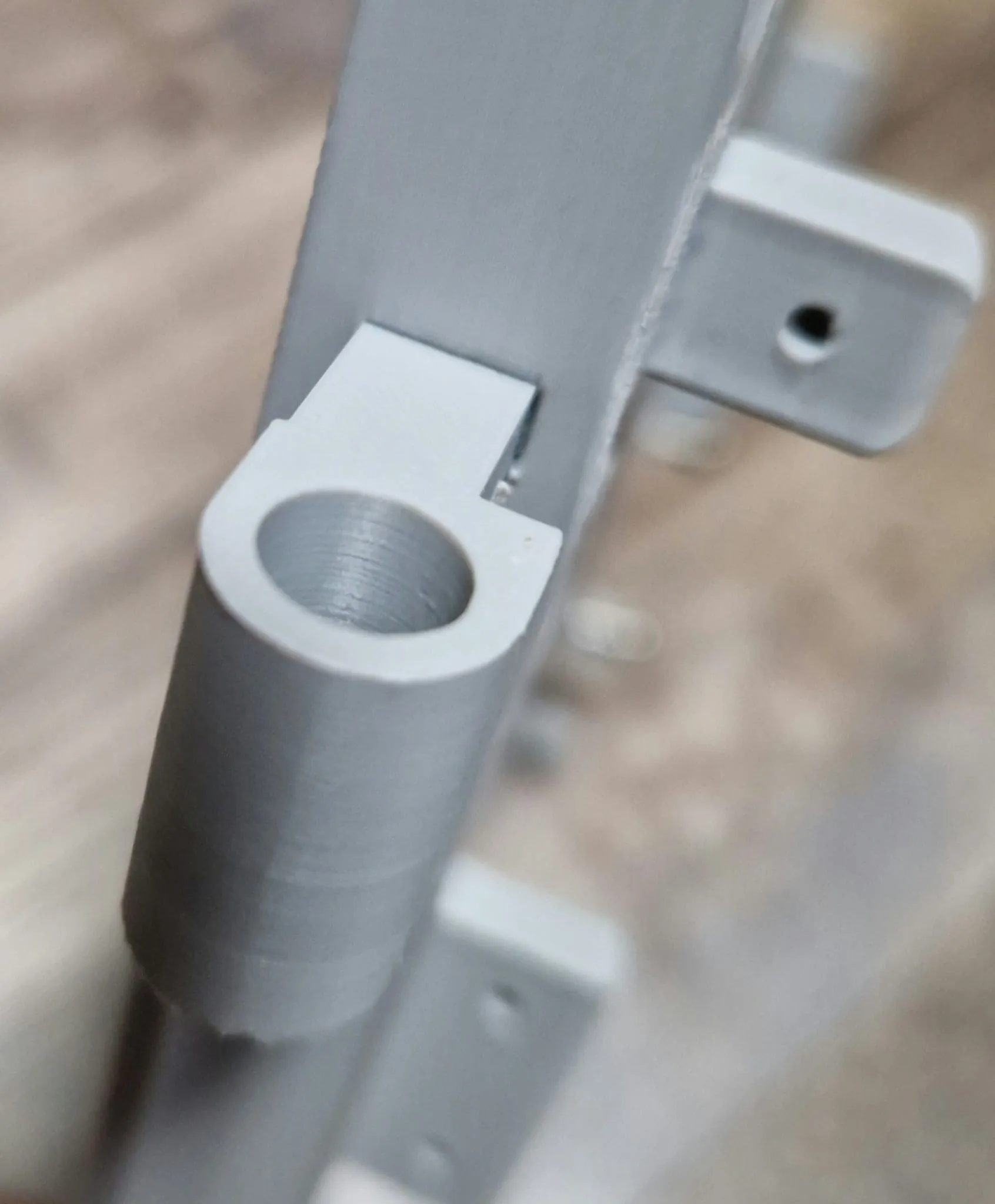
Step 7: Connect Tabletop to Main Body
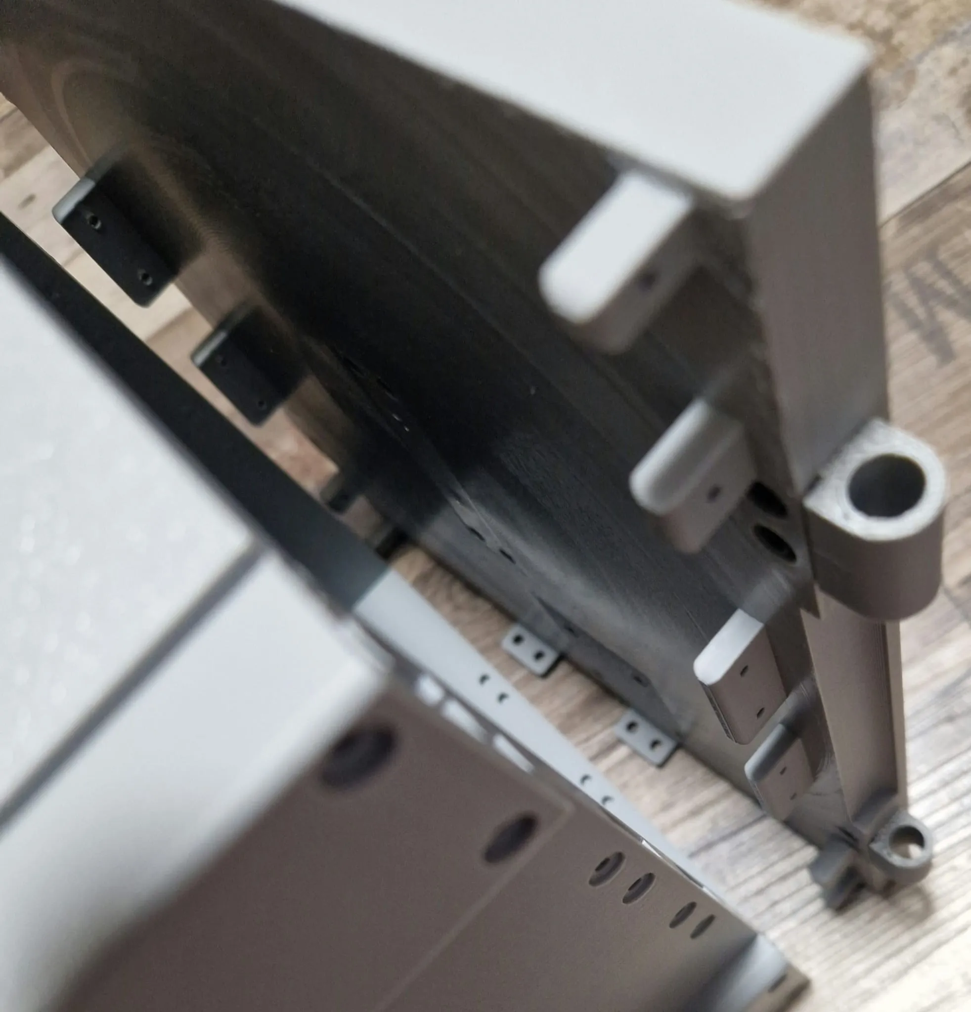
Screw in M3 x 8mm laterally, and 10 to 14mm length would also work on the outside
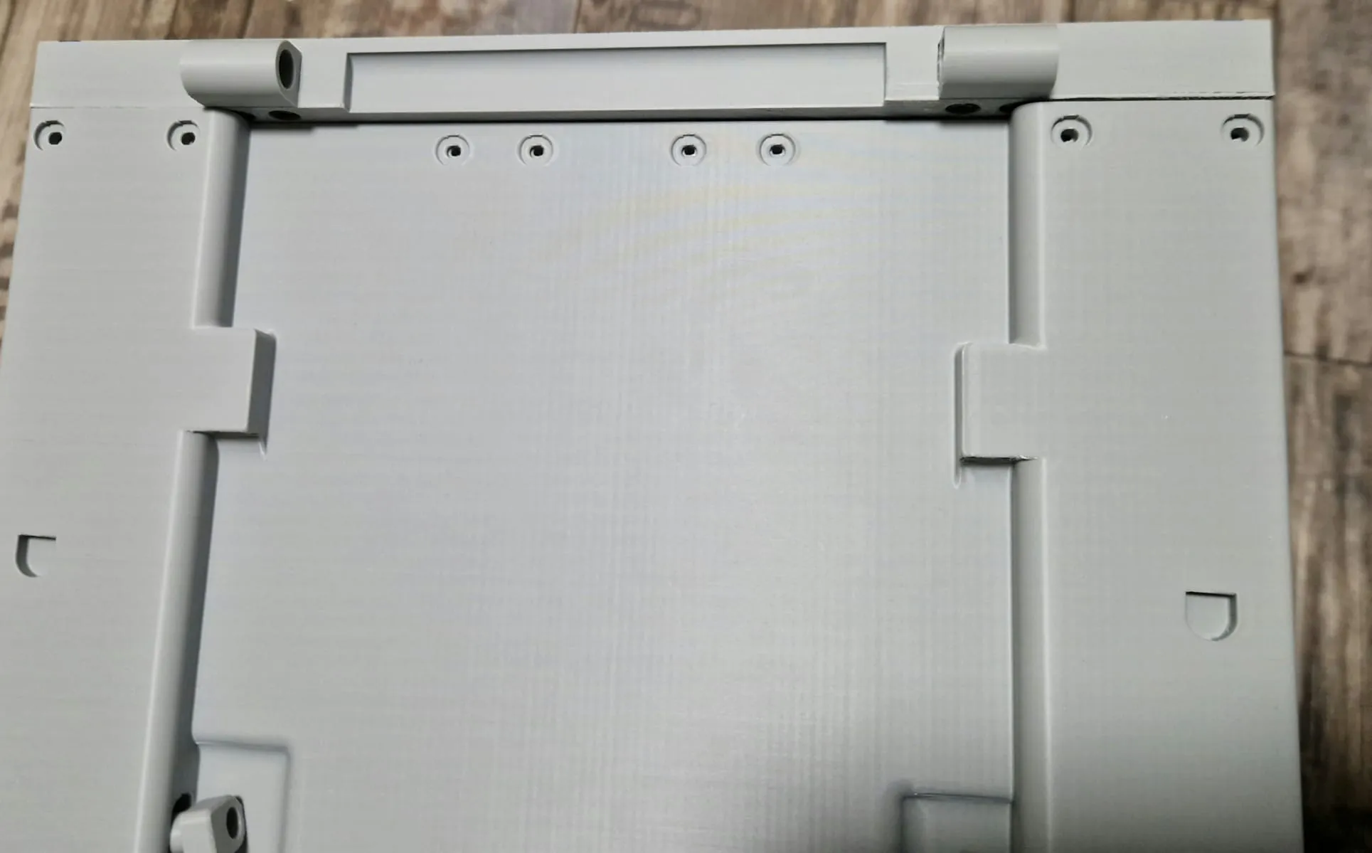
Insert 4 small pins into the top interior to fix the tabletop
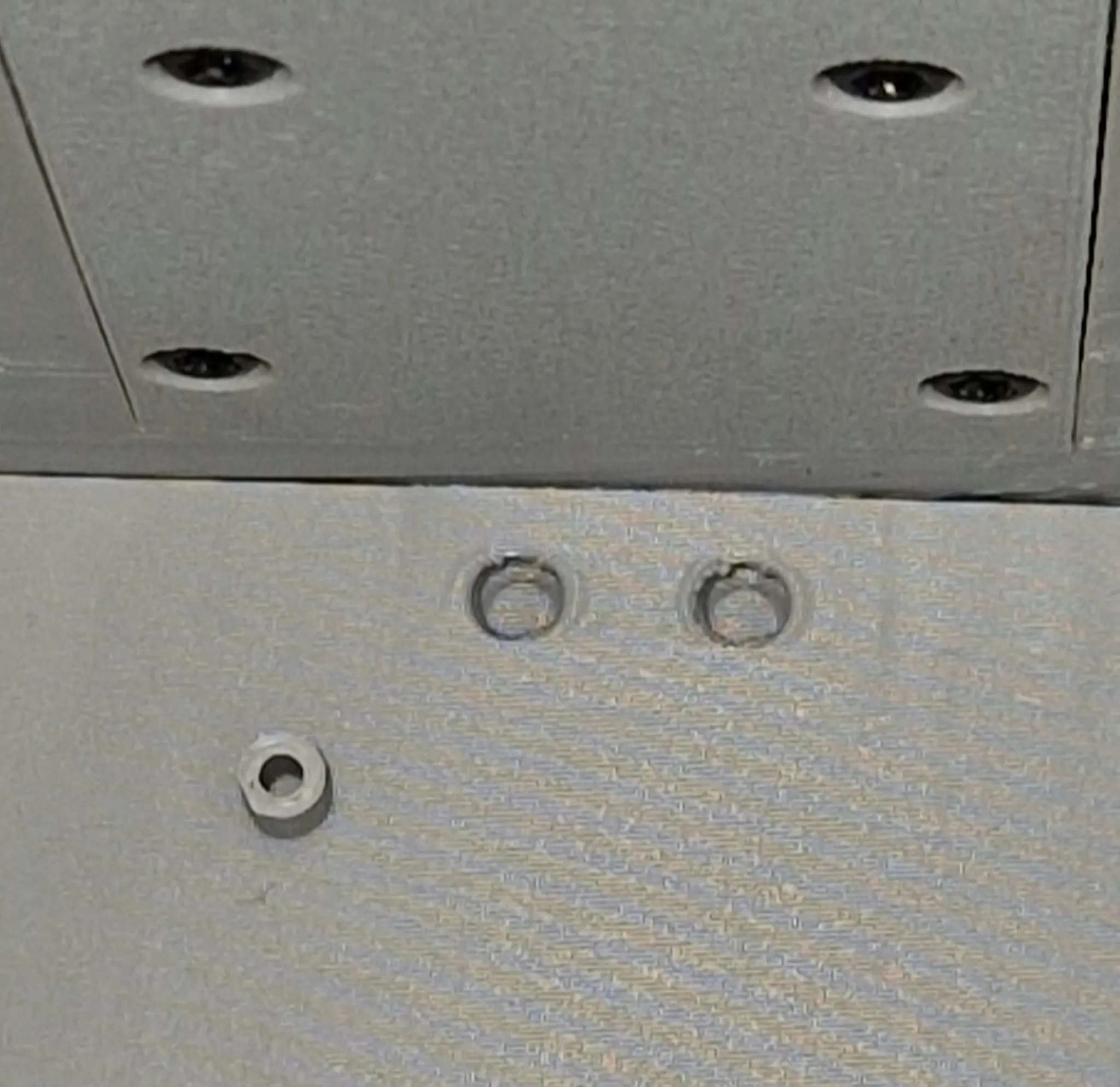
Step 8: Assemble Side Table Tops
Insert the angle into the tabletop and connect with the pins. Check function, they should fold out by gravity when the plate is turned, if not, improve the sticking points. Repeat this on the other side
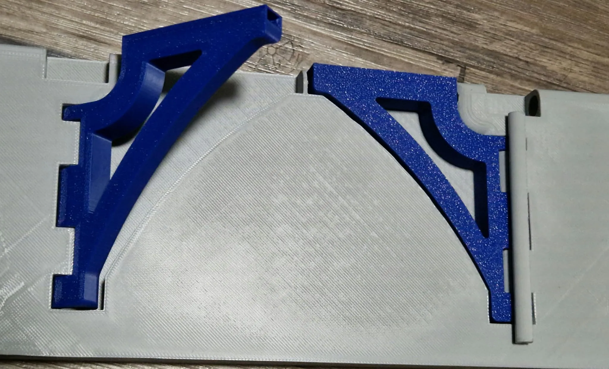
Assemble tabletop with main body, push pins in completely
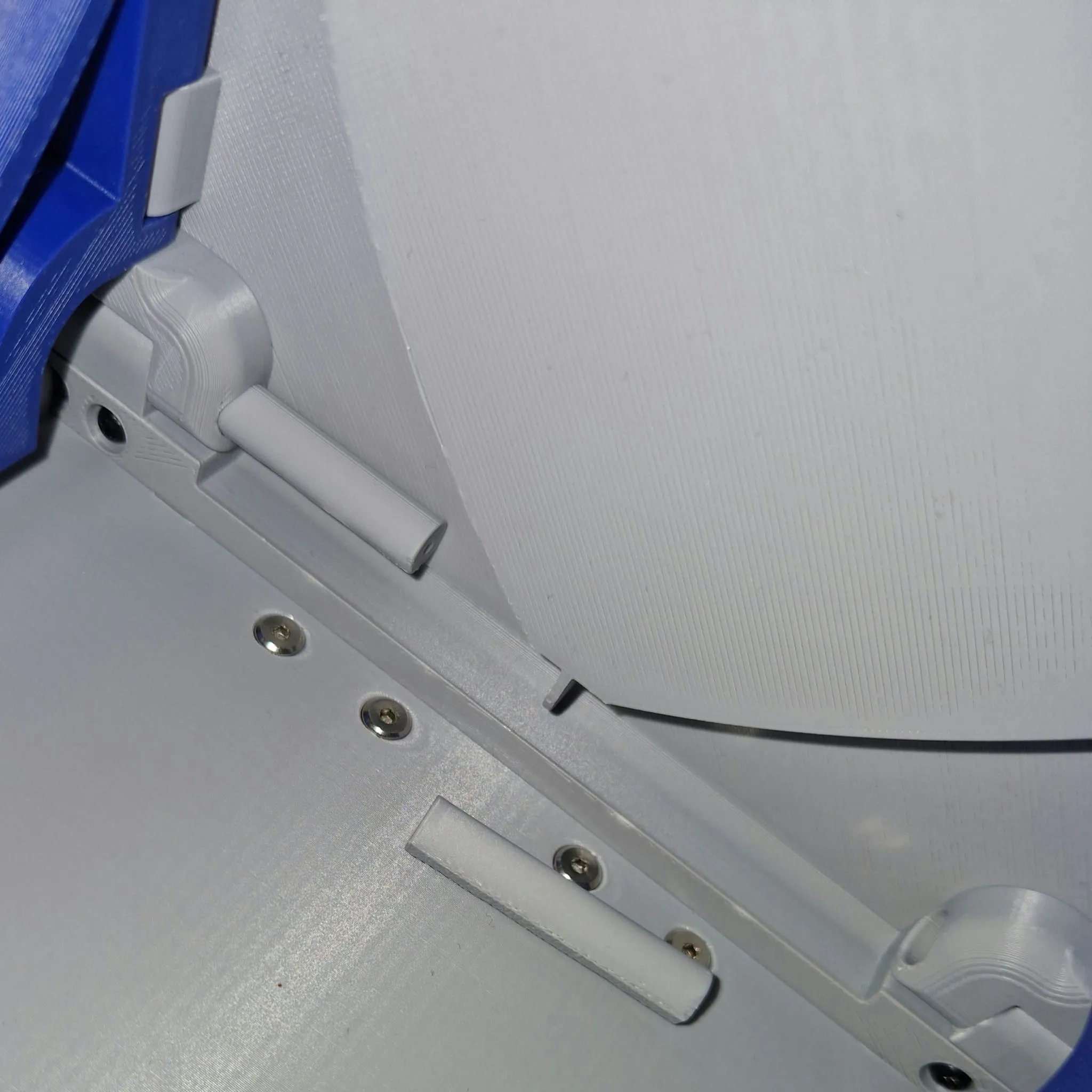
Step 9: Alignment and Magnet Assembly
- Screw screws into angle holes to adjust table height (Can be done when folded)
- Mark the 2 attracting poles of the magnets as shown in the right picture, and glue them in so that the poles attract each other
- Definitely test magnet direction beforehand to avoid incorrect assembly (Be careful in the angles, it can stay in without glue)
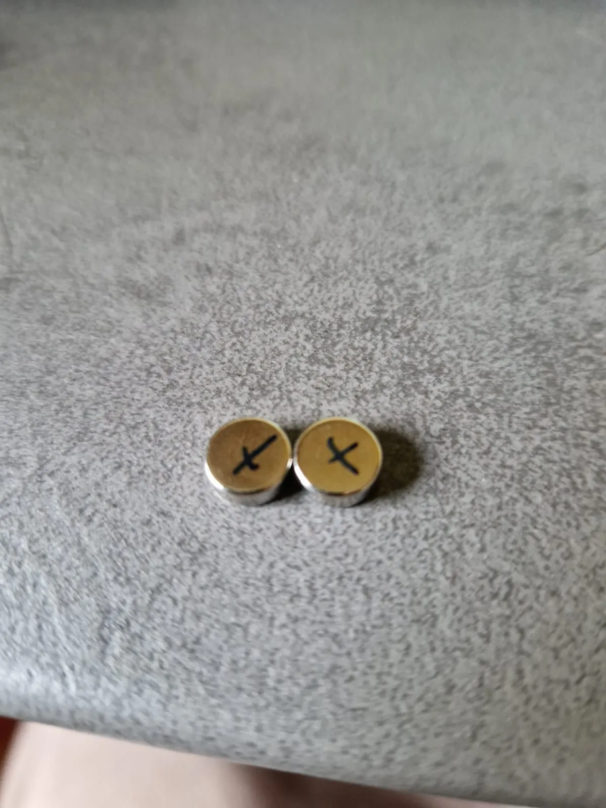
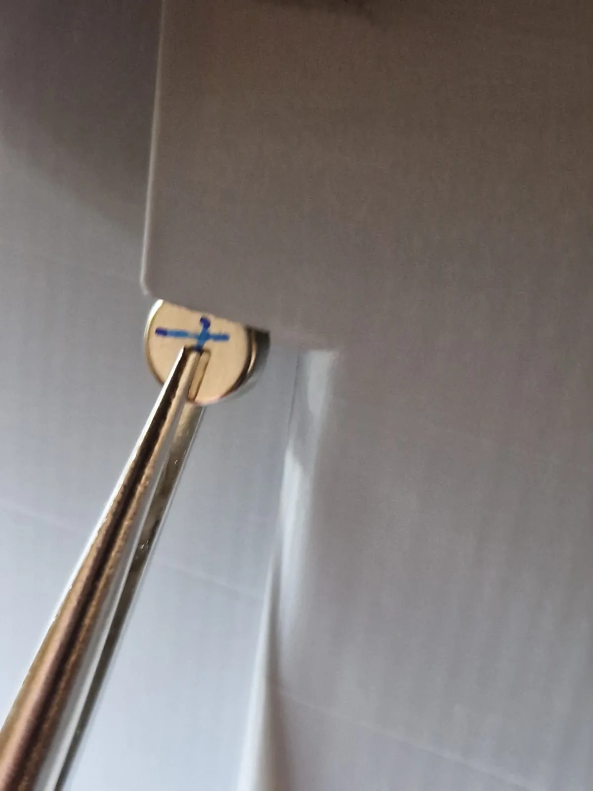
Step 10: Inserting the Inner Floors
- Open door, insert floors according to desired setup
Further floors can be created individually according to technical drawing
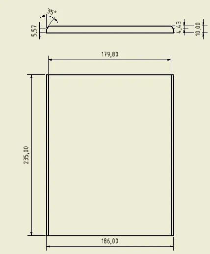
I have added screws\parts below which can be used for assembly
License

You may create derivative works based on this object, provided that all such derivative works are published exclusively on the MakerWorld platform and include proper attribution to the original creator. You may not share, upload, host, distribute, or publish this object—or any derivative work of this object—on any other digital platform, marketplace, or distribution channel. Commercial use of this object and any derivative works is strictly prohibited. This includes, but is not limited to, selling, renting, sublicensing, or using the object in any context in which you receive monetary compensation or other financial benefits.


Comment & Rating (62)