
The Mechanical Gyroscope_Three Ring Version
Print Profile(1)

Description
What is it?
This is a Mechanical Gyroscope, my entry into the Laboratory Equipment Design Contest. This one has three rings, but I plan to design one (or many) with more. Now, as I do not want to get penalized if there is some confusion as to whether this follows the theme of the contest or not, I will explain why a gyroscope is considered to be laboratory equipment. A mechanical gyroscope is considered to be laboratory equipment because it is used to measure or maintain orientation and angular velocity, which are essential for various scientific and engineering experiments. In a laboratory setting, gyroscopes may be employed to ensure accurate measurements and to maintain the orientation of instruments and equipment during experiments. They are also used in navigation systems, which are crucial for precise positioning and tracking in scientific research and development. Additionally, gyroscopes are integral to the development of inertial guidance systems, which are vital for the operation of satellites, aircraft, and other vehicles in space.
How do you assemble it?
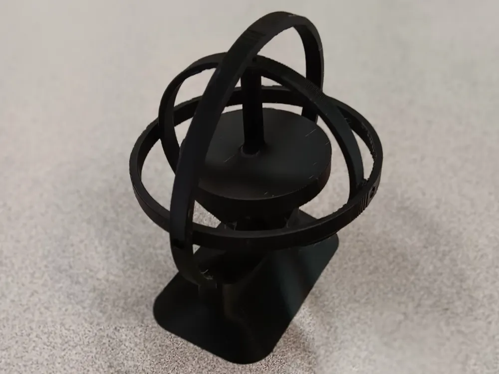
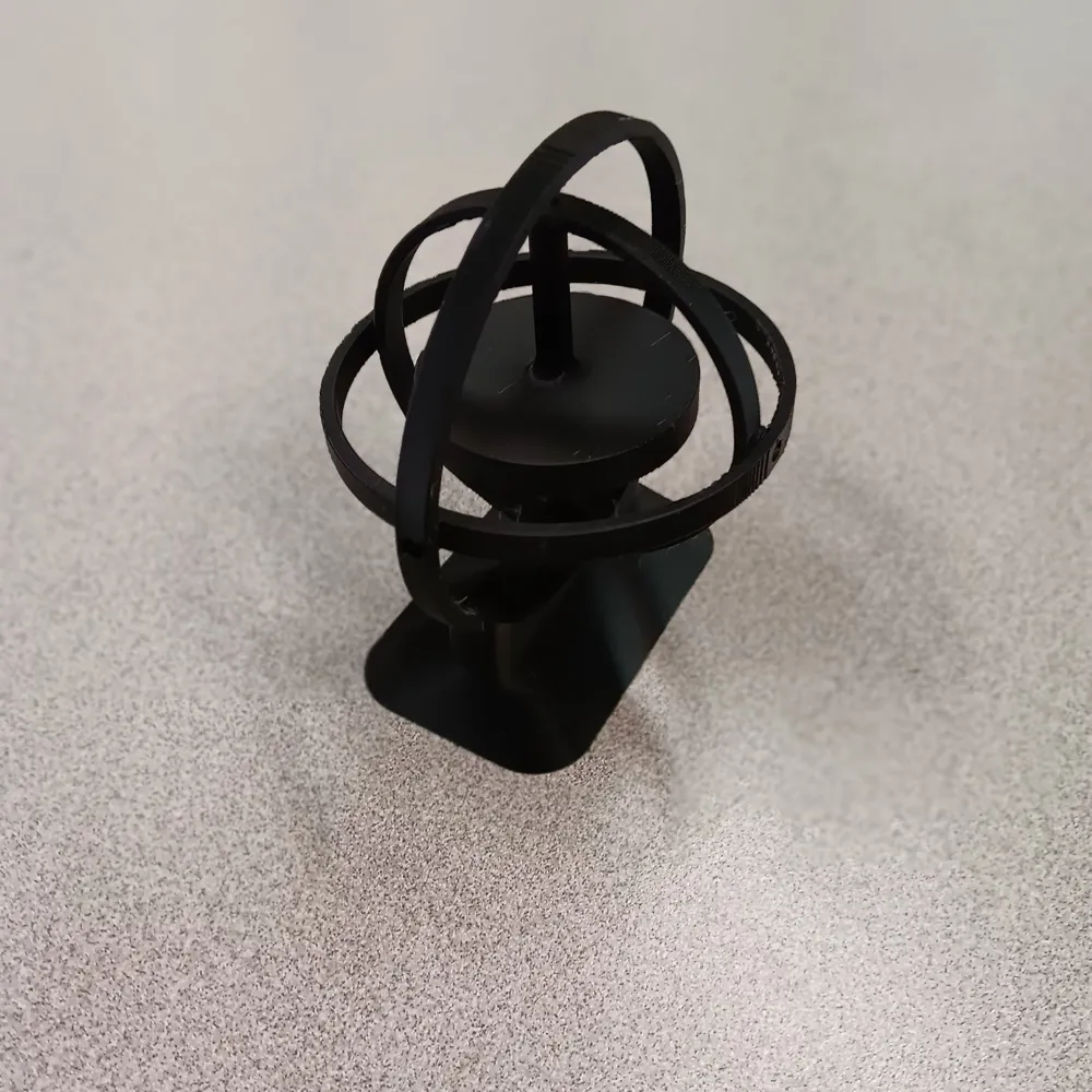
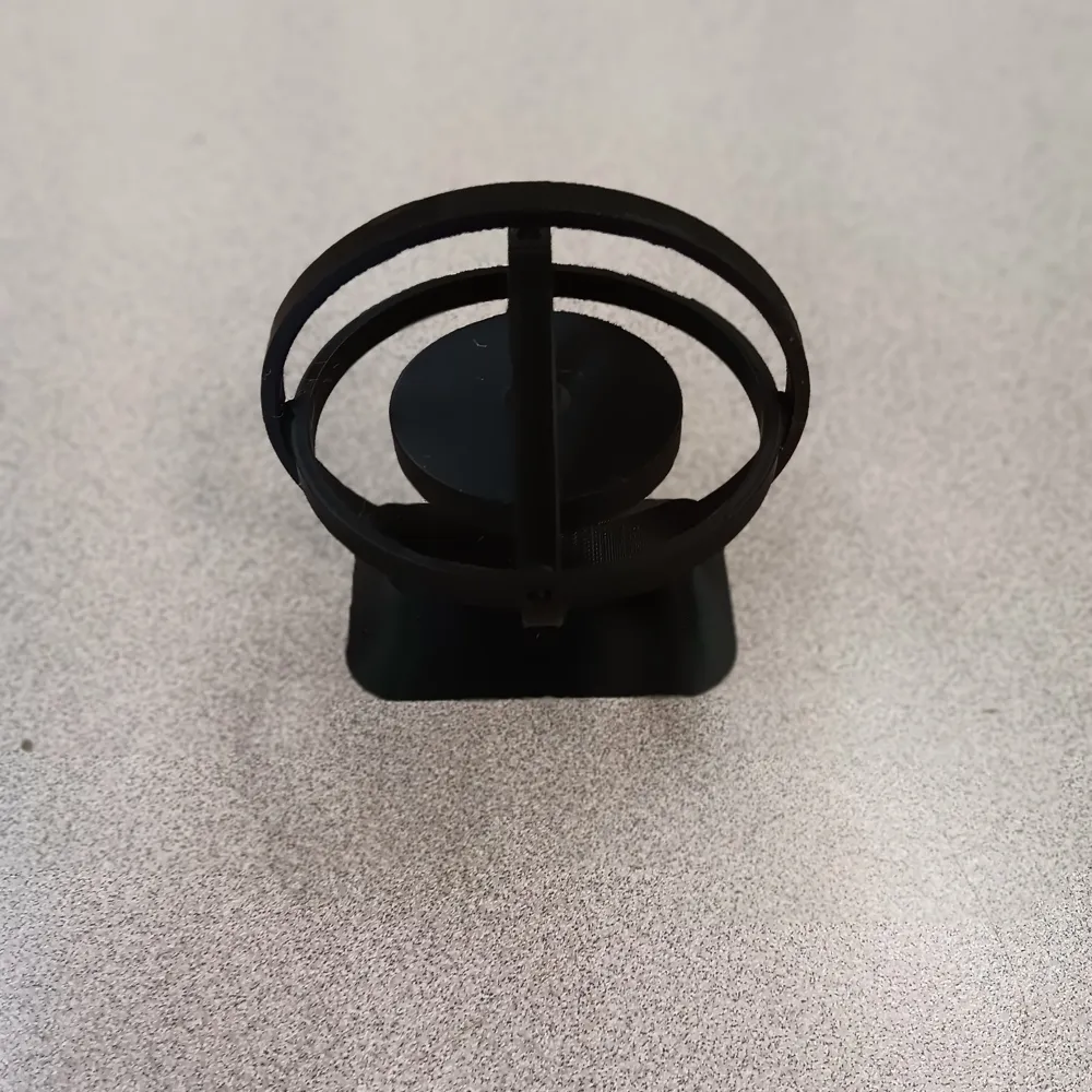
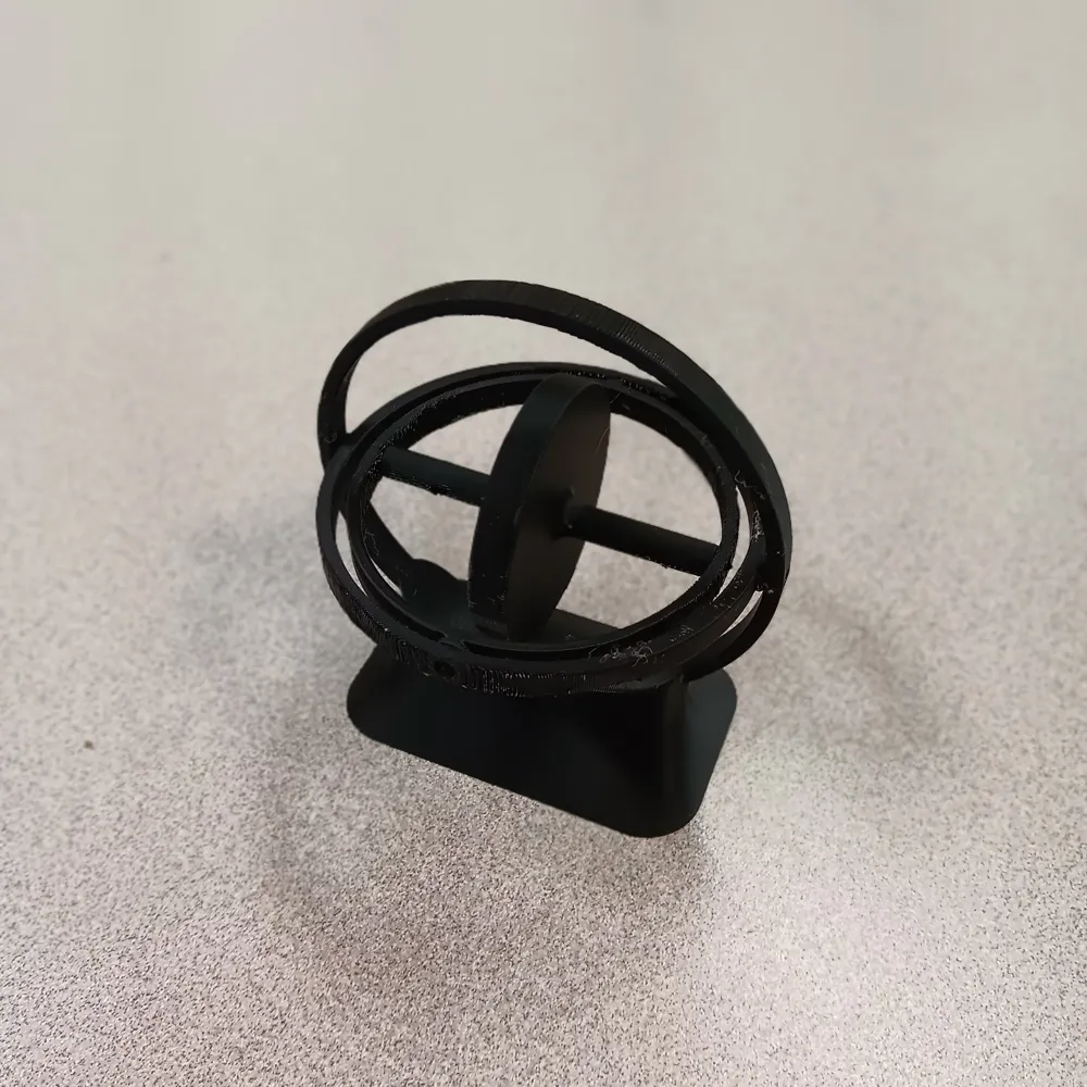
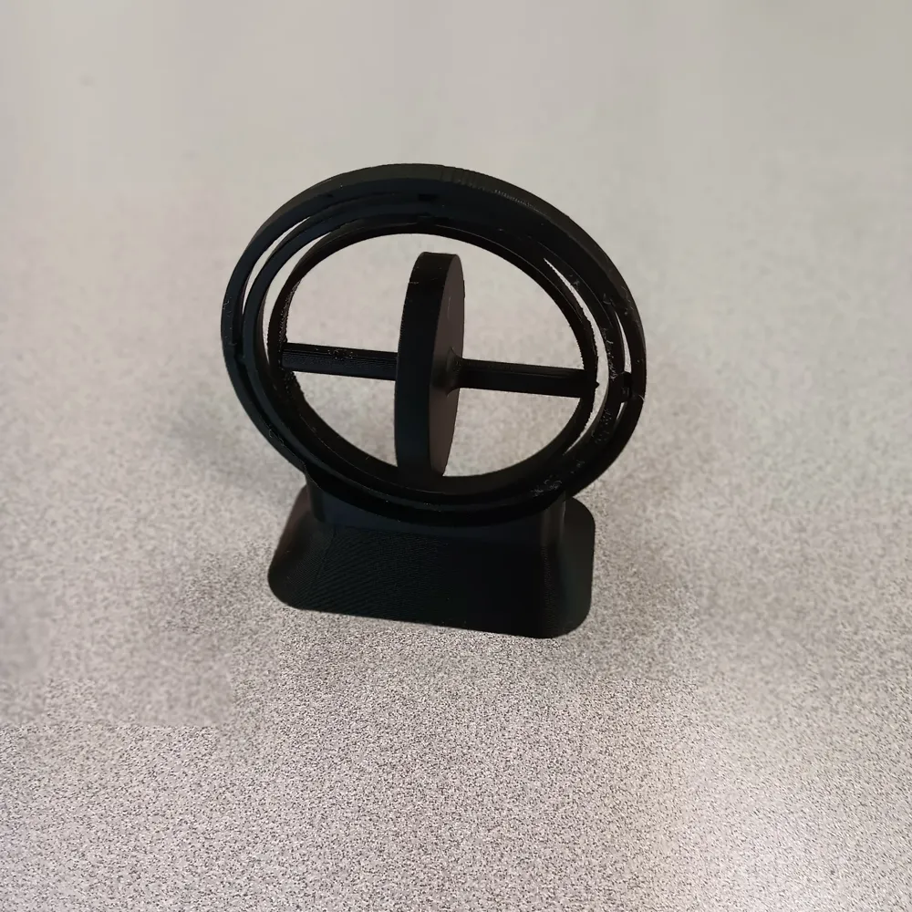
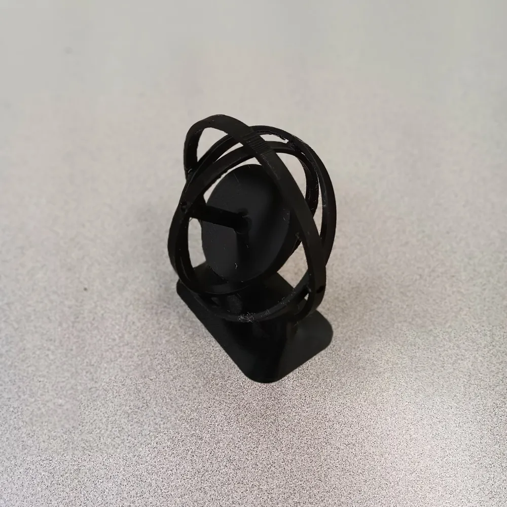
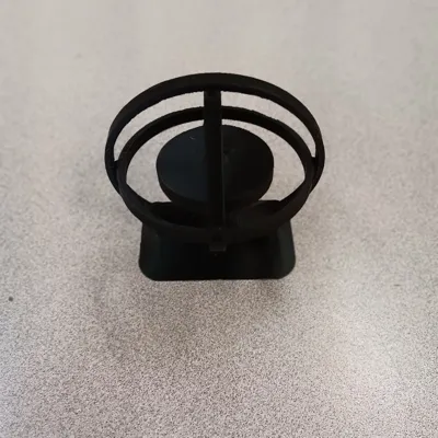
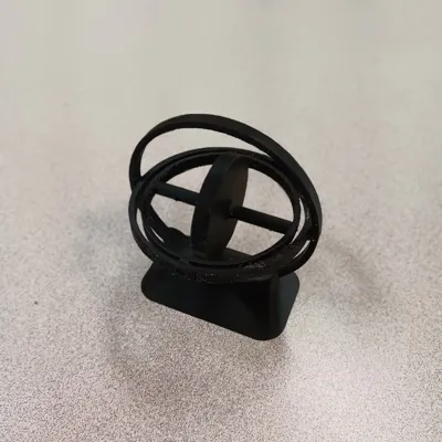
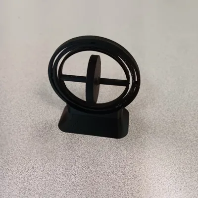
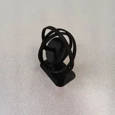
The assembly for this gyroscope once printed is very simple. You have 4 parts: the rotor, which is the core of the gyroscope, two full rings, one bigger, one smaller, and a third ring that couples as the base for the gyroscope. You will notice that the three rings have 2 holes each, and the two full rings and the rotor have 2 spikes each (if you notice that the rotor has a hole in it, its only purpose is to allow you to thread a string though it to wind it around the rotor and pull it for faster rotation). This is designed to be press fit, and everything fits together by taking advantage of the slight flexibility that the rings possess (I printed it in PLA+, so results may vary for different filament types).
- Start by fitting the rotor into the smaller full ring by sliding the spikes of the rotor into the holes of the smaller full ring.
- Now fit the spikes of the smaller full ring into the holes of the larger full ring in the same manner.
- And now, as you have probably guessed, fit the spikes of the larger full ring into the holes of the base ring.
And that's it, assembly complete! You now have a small, interactive decoration that can demonstrate 3-axis rotation.
Final Notes
Keep in mind that this is more of a representation that functions similarly to a real, professional, mechanical gyroscope, not as a real, professional, mechanical gyroscope. This is, regrettably, unavoidable as metal would truly be the only way to make a reliable, working gyroscope as the filament doesn't weigh enough to retain the centrifugal force required to maintain a high RPM long enough to get accurate measurements. But it is still very cool and worth printing. I hope that you enjoy it as much as I have!
License

You shall not share, sub-license, sell, rent, host, transfer, or distribute in any way the digital or 3D printed versions of this object, nor any other derivative work of this object in its digital or physical format (including - but not limited to - remixes of this object, and hosting on other digital platforms). The objects may not be used without permission in any way whatsoever in which you charge money, or collect fees.


Comment & Rating (6)