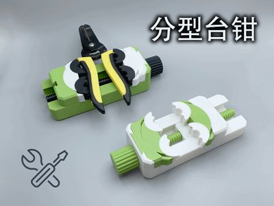
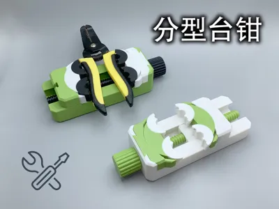
Splitting Vise (No hardware needed, compact, smooth, and sturdy)


Print Profile(2)


Description
This model is a self-centering clamp measuring 185*70*43mm with a clamping range of 0-100mm—a compact and practical design.
Its features include a hardware-free construction, smooth operation, robust practicality, support-free printing, and an expansive clamping range.

Features:
- Printing requires approximately 6 hours and 170g of filament due to the vertical orientation of the bolt, slightly extending printing time.
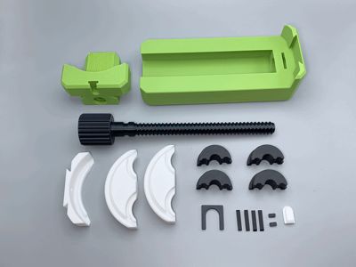
- The assembly comprises approximately 18 components (right image), yet remains straightforward and requires minimal manual assembly.
- All parts print without support (although the slicer may suggest otherwise; disregard this suggestion).
- All parts exhibit flawless surface finishes on sliding surfaces, ensuring smooth operation.
- Component tolerances have been rigorously tested, and default print settings are suitable.
- The main bolt incorporates a limit stop, preventing slippage and allowing for component replacement.
- Prior to assembly, please follow the video instructions; the assembly process includes unconventional steps.

Assembly Instructions:
1, Begin by installing one side and fitting the limit pin (the limit pin features a rounded end that interfaces with the back; ensure correct orientation. If incorrectly installed, use a needle to remove and reinsert)

2, Install the second black component, rotating it to expose the slot, and install the second limit pin using the same method as above (again, ensure correct orientation).

3, Repeat this process for the second clamping surface (identical in shape). The sliding base incorporates inherent supports that can be easily removed, and the support structure may be discarded. Install the rear limit pin.

4, Install the rear limit pin and screw in the slide rail.

5, Install the main shaft and clamping surface limit pins, inserting them into the dovetail slot. A retaining rib is present; the dovetail slot should remain secure after printing. If any looseness occurs due to variations in material shrinkage, use thin card to shim.
*The innovative multi-slot design, the uniquely designed arcuate clamping surface connection method, and the pin limit stop enable completely support-free printing with exceptional strength.
*The independently designed vertical print, solid-section bolt (addressing potential mid-layer infill issues that can weaken the Z-axis) incorporates front and rear limit catches.
*The elongated slider design significantly reduces the deformation load on the main bolt; hence, vertical bolt printing is employed, suitable for light-duty applications, with the clamping range extended to 100mm.
*We hope this will be beneficial to many.
License
You shall not share, sub-license, sell, rent, host, transfer, or distribute in any way the digital or 3D printed versions of this object, nor any other derivative work of this object in its digital or physical format (including - but not limited to - remixes of this object, and hosting on other digital platforms). The objects may not be used without permission in any way whatsoever in which you charge money, or collect fees.
Comment & Rating (73)