
A1 Power Supply Module – Bambu Hub
Print Profile(2)


Description
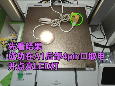
After several days away from home without access to a computer, I finally returned after an eight-hour drive, immediately firing up my computer to provide this update for my fellow enthusiasts
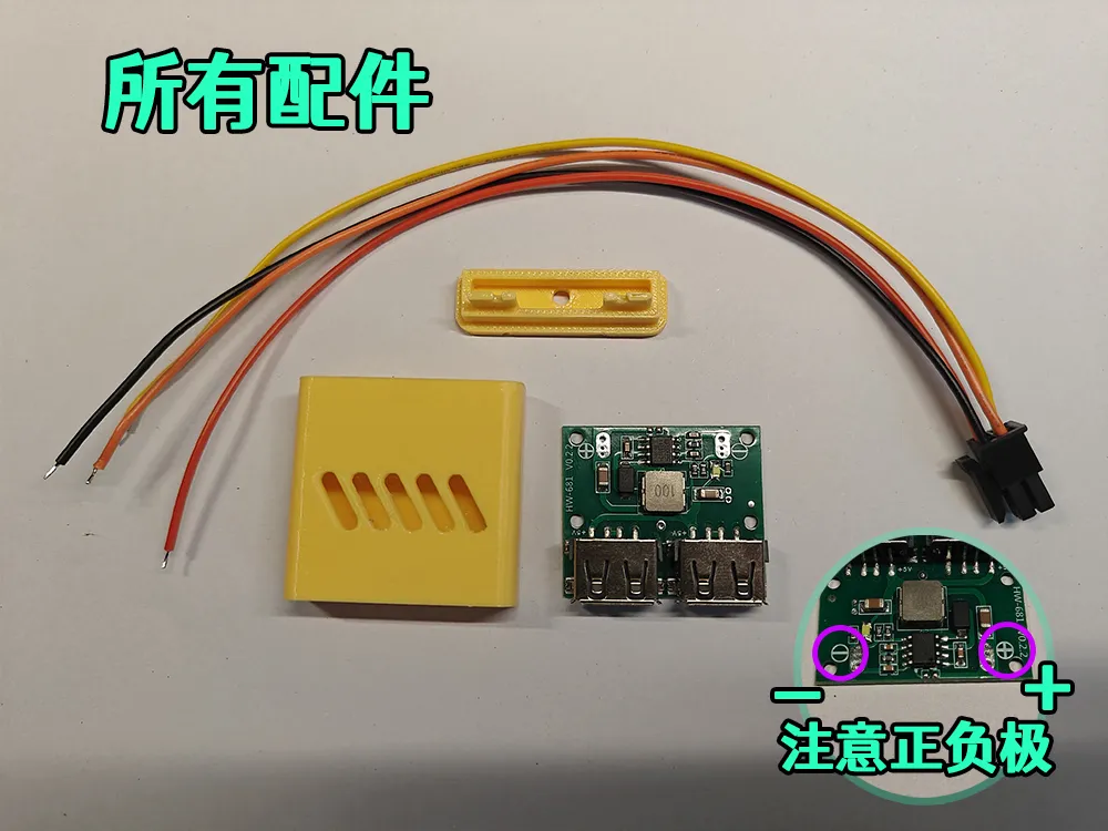
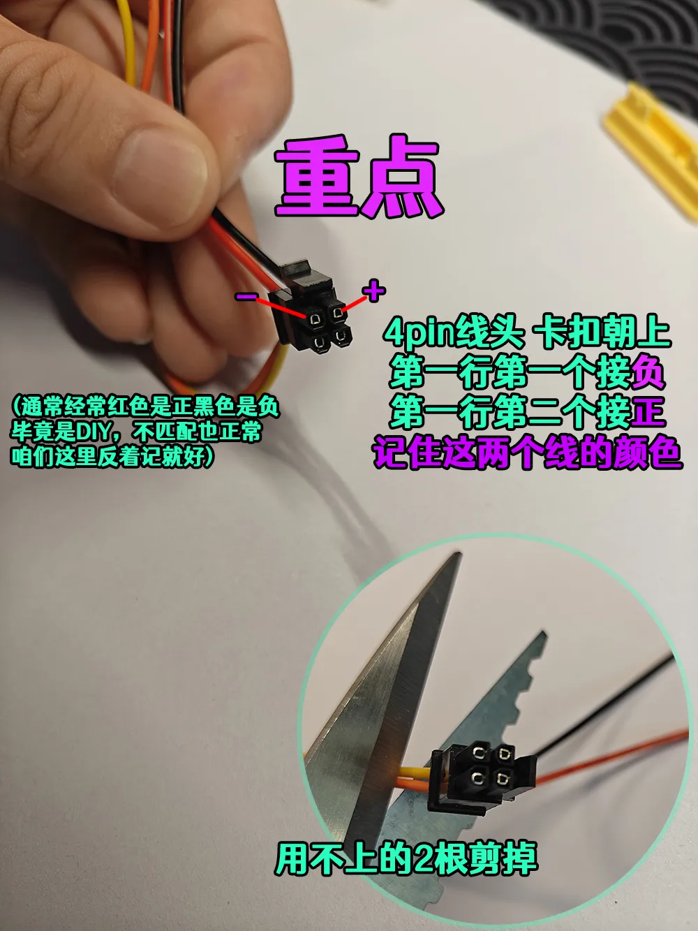
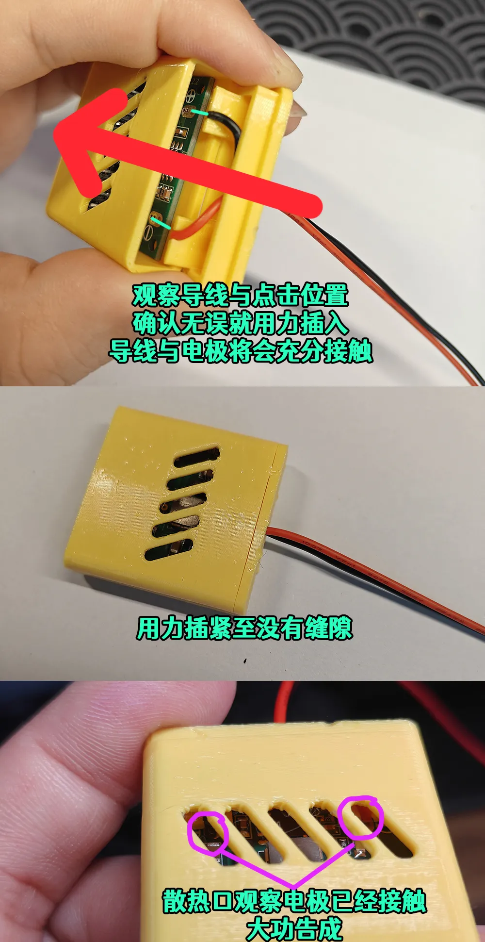
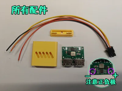
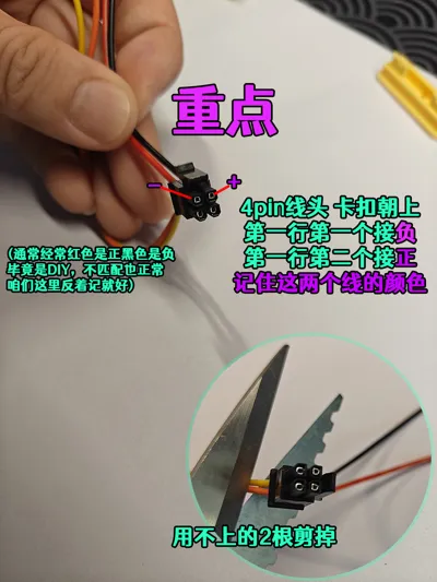
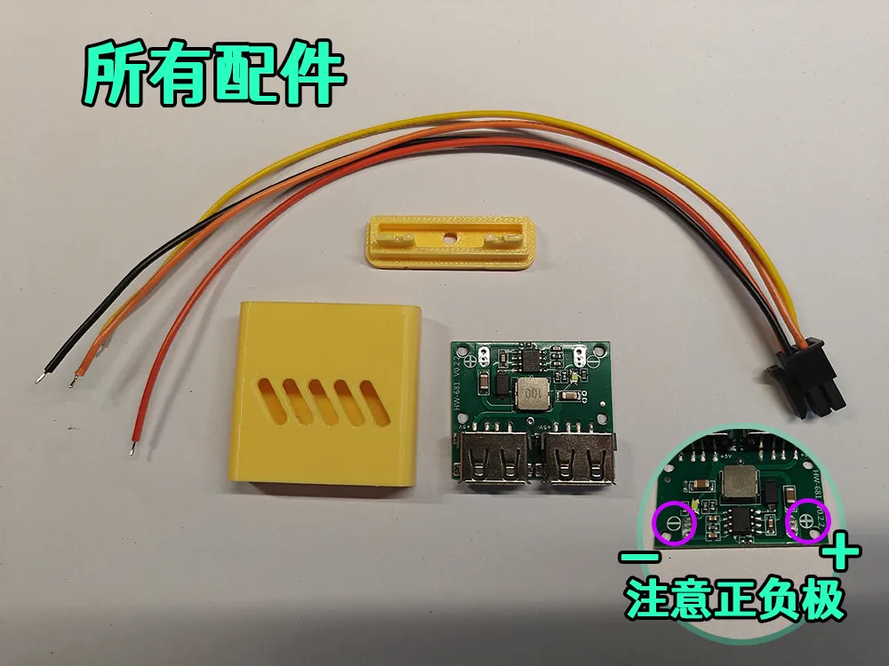
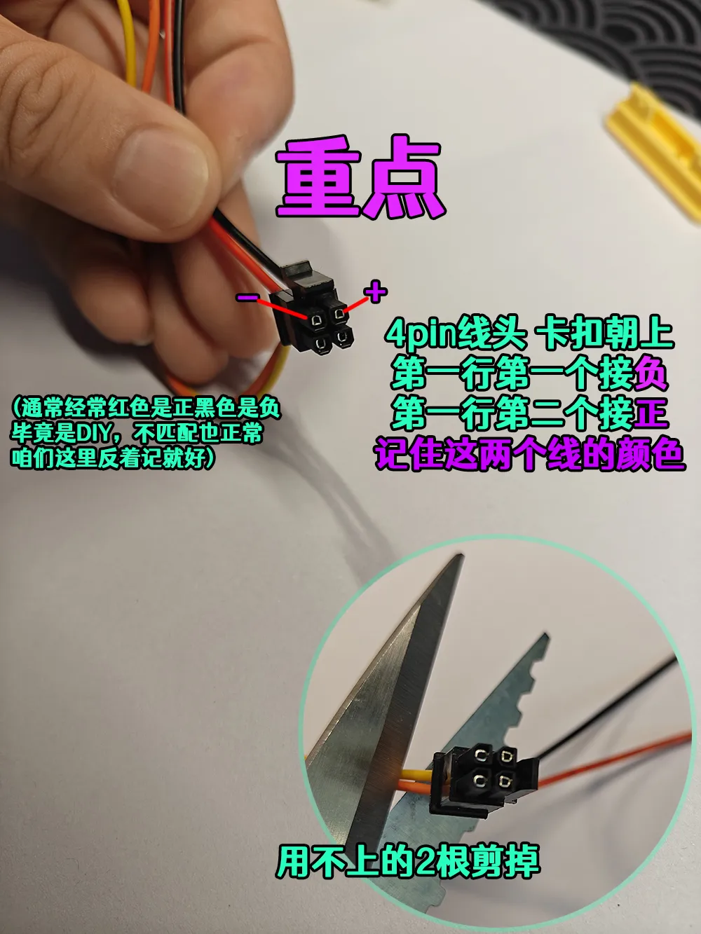
Caution: Some users have inadvertently reversed the wiring, resulting in a damaged power module. Those undertaking this project must carefully review the “key points” image; the wiring is reversed from standard practice! Red is negative and black is positive for this specific application. Repeat, for this specific application, Red is negative and black is positive. Repeat, for this specific application, Red is negative and black is positive.
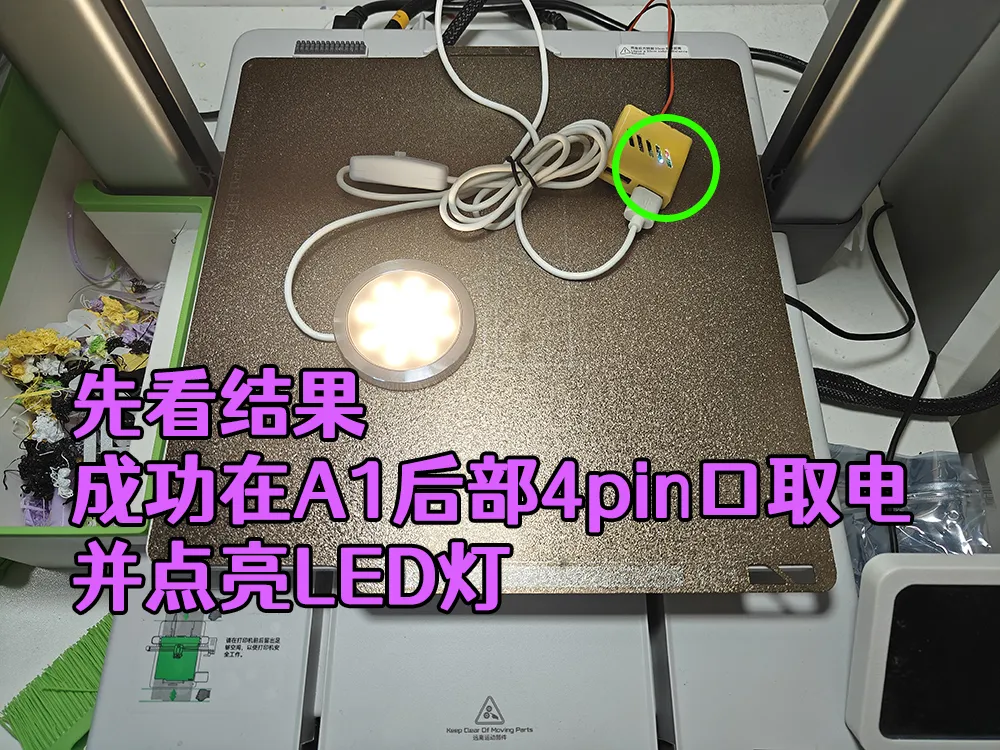
I frequently require LEDs, small fans, and cameras to support my printer, but using individual power adapters for each device is cumbersome
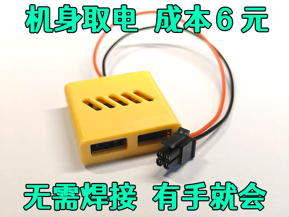
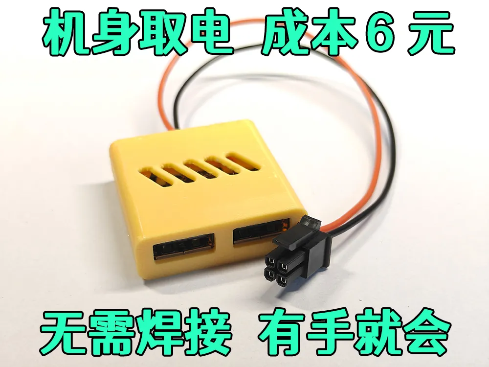
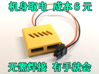
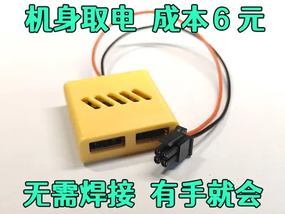
Thus, I created a small device to draw power from the printer’s 4-pin interface, which I have named the Bambu Hub
The printer operates on 24V, which is then converted to 5V using a step-down module
Recognizing that many may lack soldering experience, I’ve endeavored to simplify the design for ease of assembly,
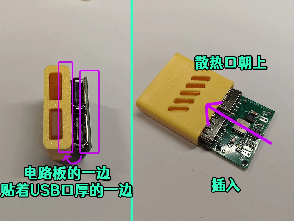
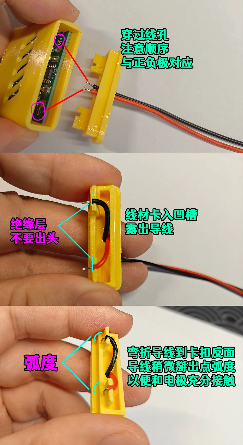
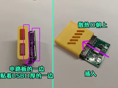
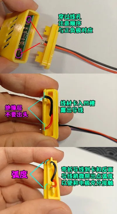
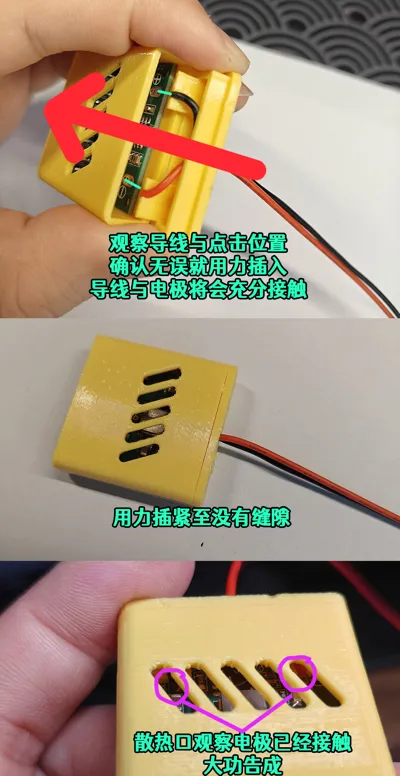
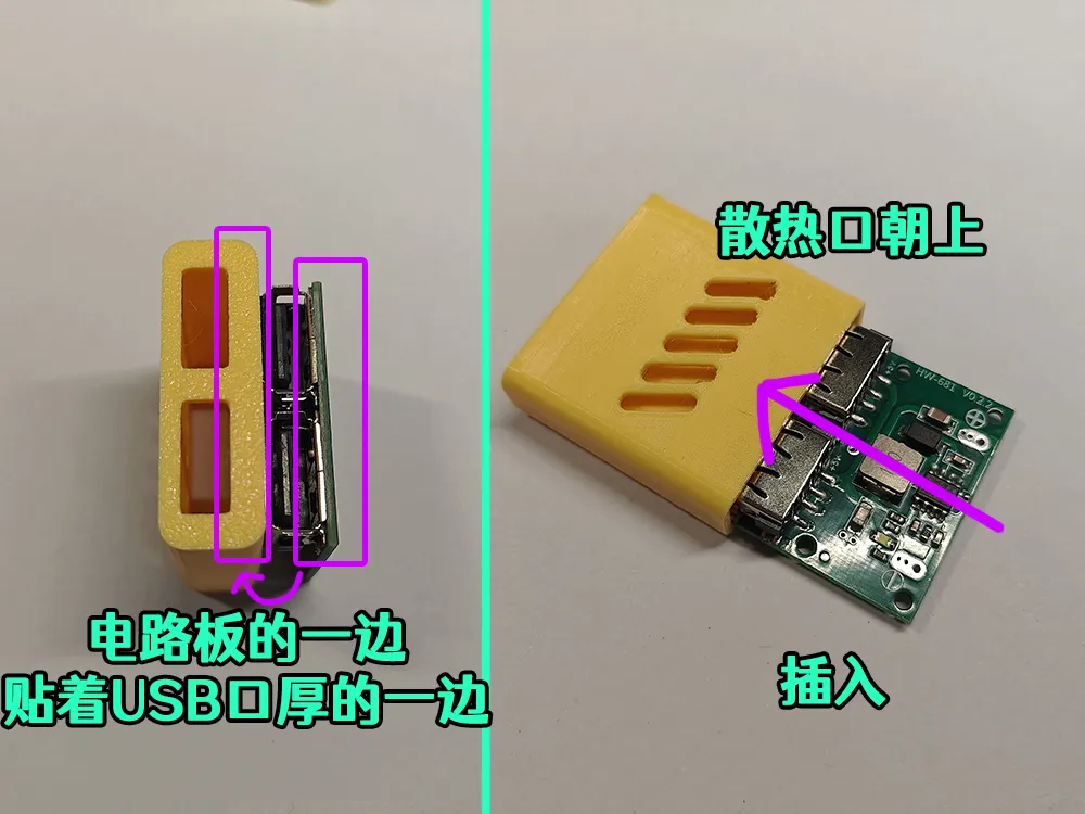
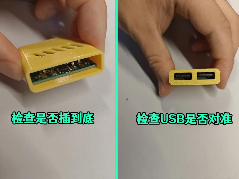
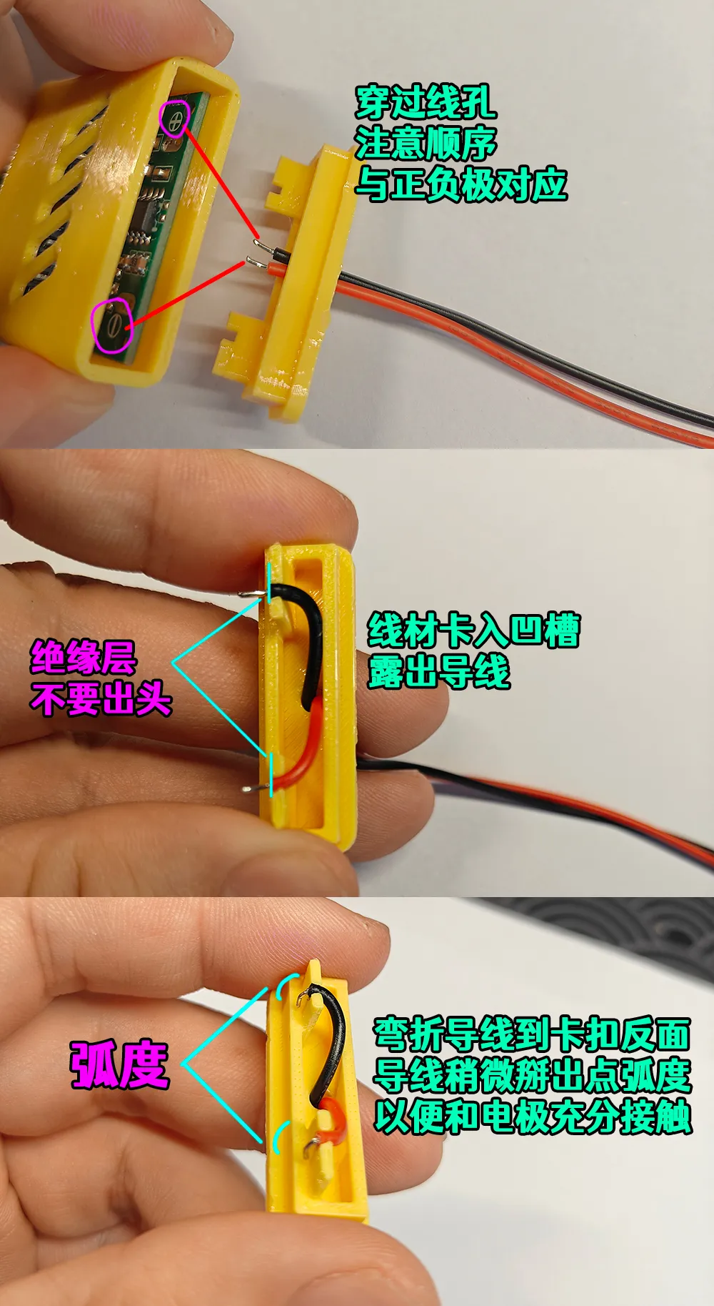
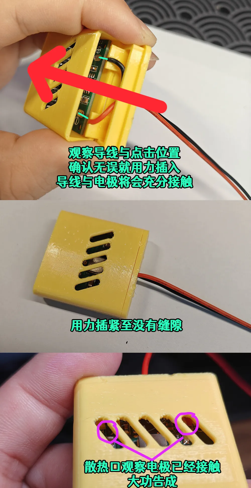
Employing two card structures and the 0.2mm gap of the circuit board to precisely position and secure the wires, eliminating the need for soldering
The wires are firmly clamped, eliminating contact concerns. I’ve personally tested the assembly by gently tugging on the wires; the connection remains quite secure
Those proficient in soldering may opt for a more robust and durable soldered connection. A model of the back cover for the soldered version has been uploaded
I’ve found PETG to provide a sufficiently tight fit for the intended purpose. PLA has not been tested
As I do not own a P1 or X1, testing has not been performed. However, theoretical compatibility exists
If using a 6-pin cable, the specific positive and negative pins must be ascertained through testing, as I lack the necessary equipment
Interested individuals are welcome to conduct their own tests
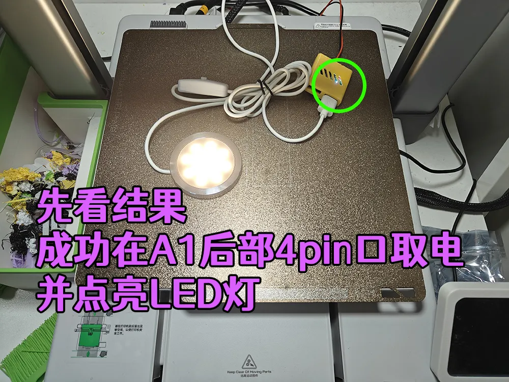
Disclaimer: DIY electrical projects involve inherent risks. Please assess your capabilities accordingly. This device is only suitable for low-power devices such as heatsinks, LEDs, and cameras. High-power devices are strictly prohibited
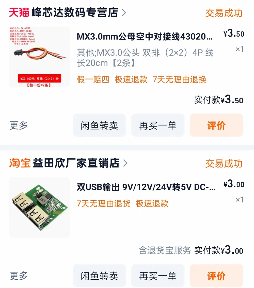
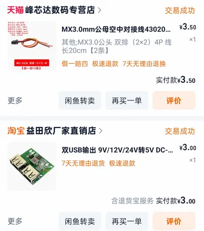
Component Links: (Hyperlinks below)
Step-Down Module MX3.0 Cable (4-pin)
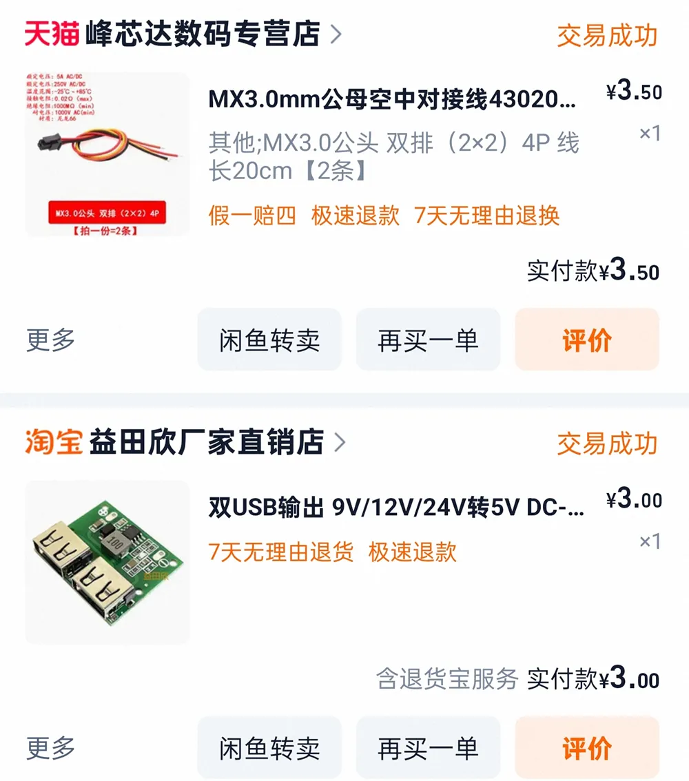
The module requires no selection; simply purchase it. For the cable, ensure you purchase a “male dual row 2x2 4-pin” type
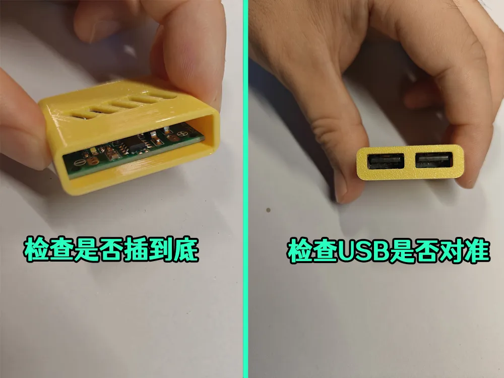
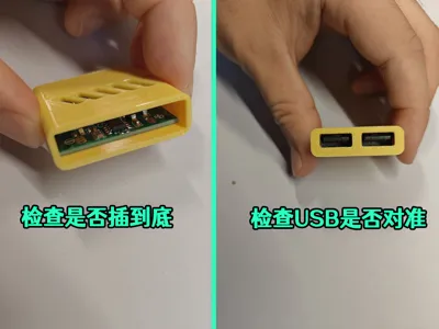
Assembly instructions follow:
License

You shall not share, sub-license, sell, rent, host, transfer, or distribute in any way the digital or 3D printed versions of this object, nor any other derivative work of this object in its digital or physical format (including - but not limited to - remixes of this object, and hosting on other digital platforms). The objects may not be used without permission in any way whatsoever in which you charge money, or collect fees.


Comment & Rating (0)