


Windmill MK2 / self-aligning + kugelgelagert
Print Profile(2)
Bill of Materials



Description
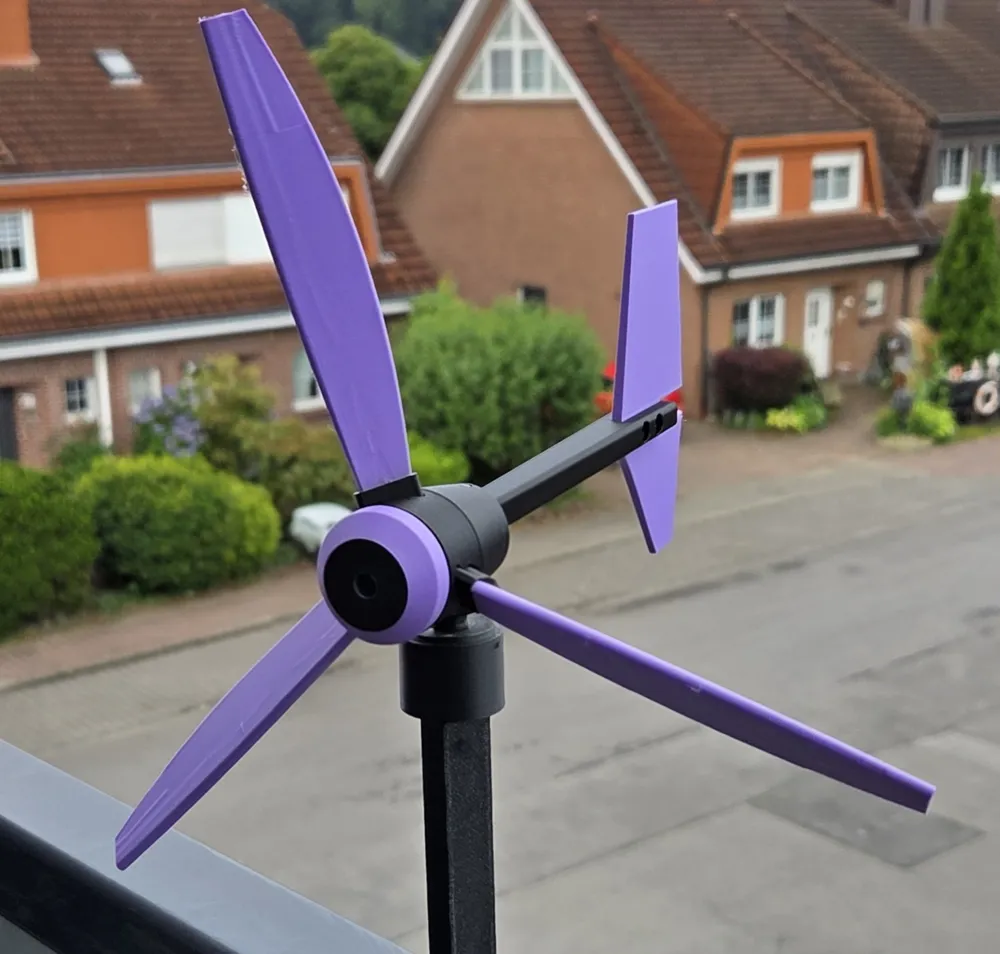
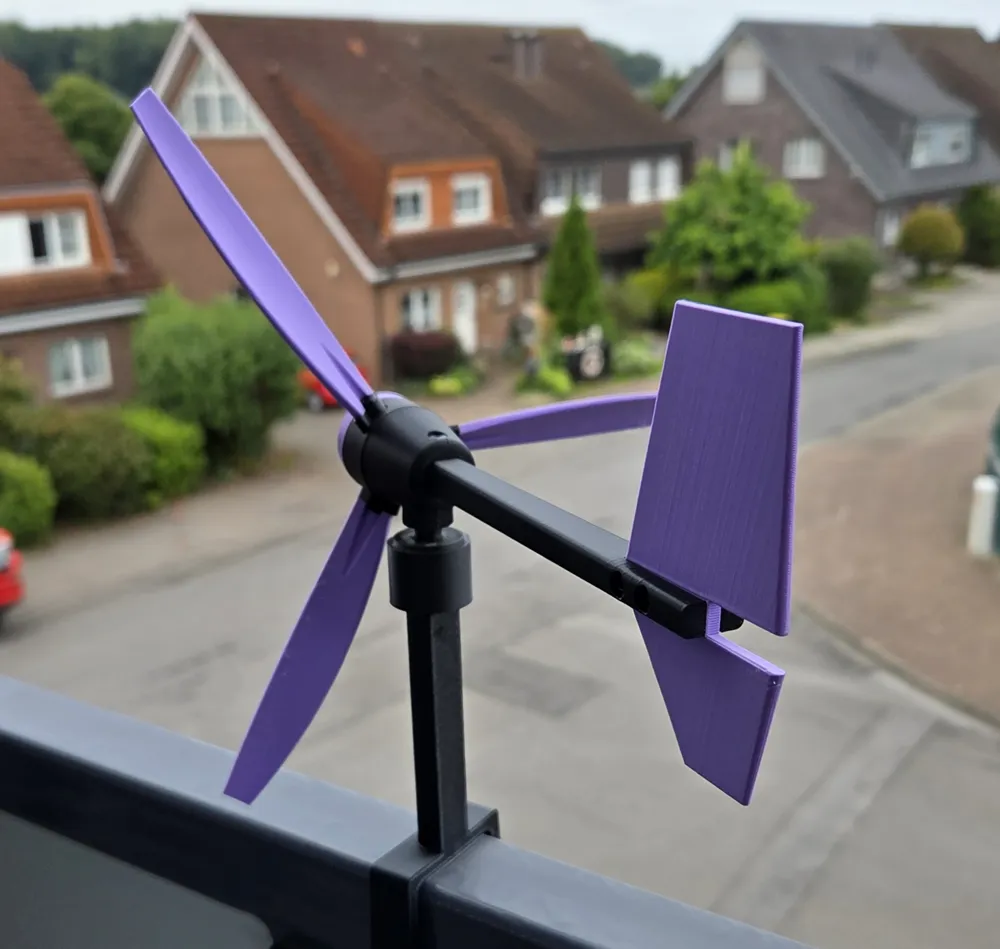

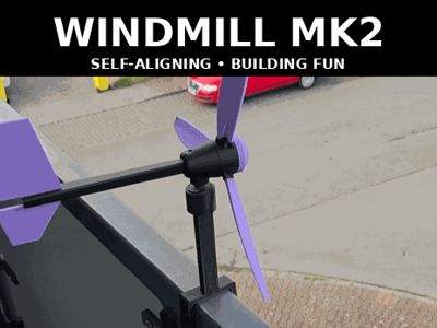
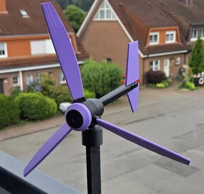
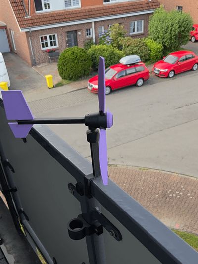
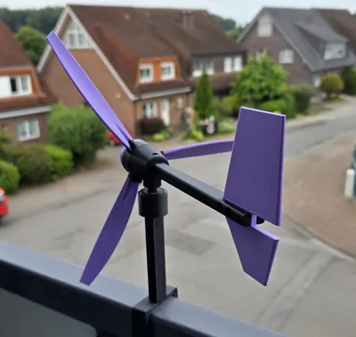
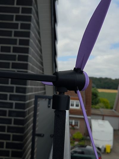

WINDMILL MK2
🔩 screwed blades, fin, mounts etc.
Hier findest du meine → Windmühlen
🖨️ 3D Printed Parts
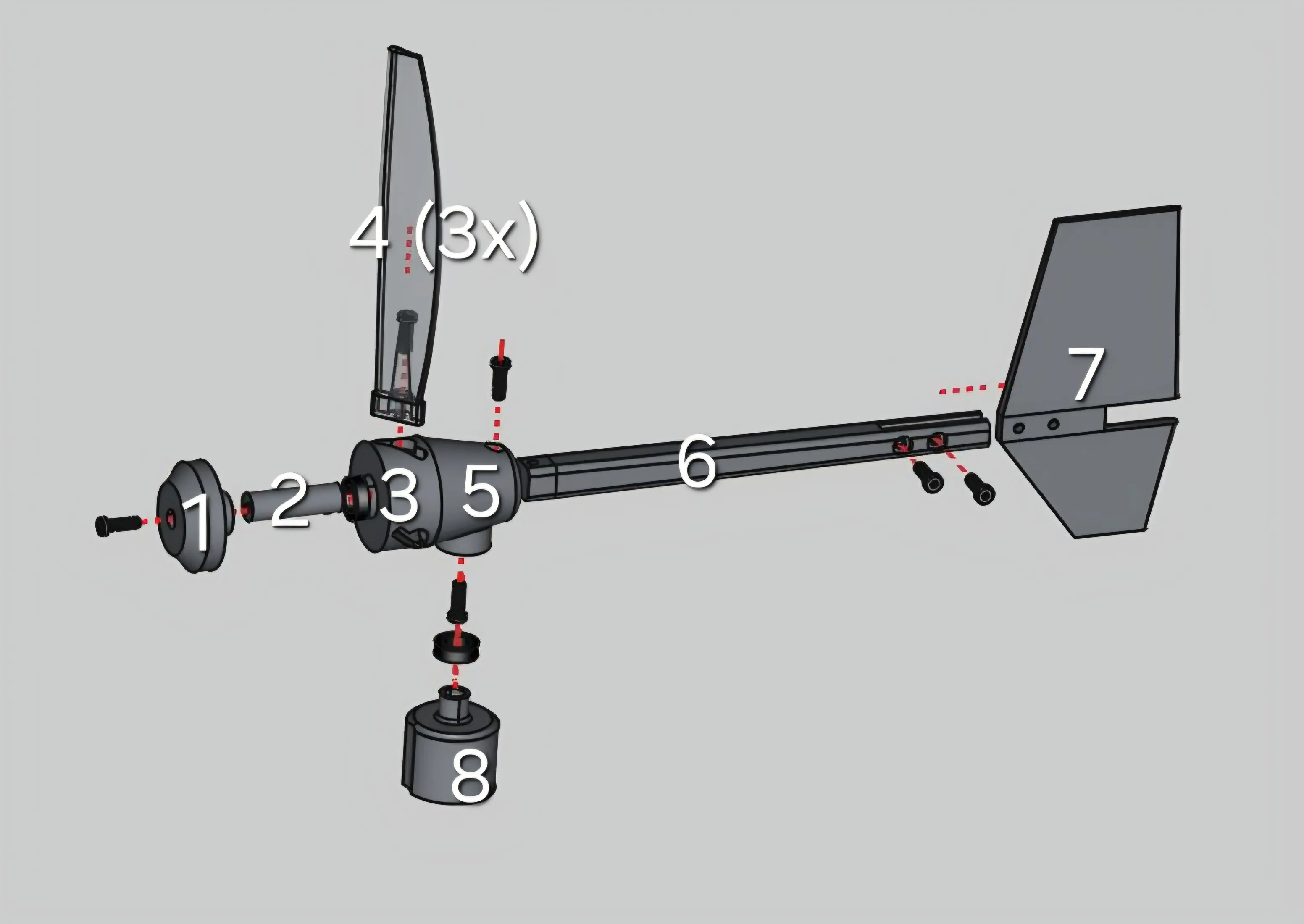
Part 1 – Hub
Part 2 – Axle
Part 3 – Rotor
Part 4 – Blades (×3)
Part 5 – Rear-Hub
Part 6 – Fin-Mount
Part 7 – Fin
Part 8 – Mount (for 10 mm Stick)
🧩 Non-Printed Components
8× 3×8 mm SHCS self-tapping screws
2× MR128 ball bearings (8 mm ID × 12 mm OD × 3.5 mm height)
🛠️ Tools Required
Large hex key (included in Bambu Lab Tool Set)
🔧 Step-by-Step Assembly Guide
Step 1 – Assemble the Hub
Take Part 1 (Hub) and screw it firmly into Part 2 (Axle).
Make sure the axle is centered and tightly fixed in the hub.
Step 2 – Attach the Blades
Secure the 3× Part 4 (Blades) to Part 3 (Rotor) using screws.
Step 3 – Insert Bearing into Blademount
Press the first MR128 bearing into Part 3 (Rotor).
The bearing only fits from one side – make sure it is fully inserted.
Then slide the blademount onto Part 2 (Axle).
Step 4 – Assemble Rear-Hub
Insert the complete front assembly (Hub, Axle, Rotor, Blades) into Part 5 (Rear-Hub) via the axle.
From the bottom, screw the axle into place.
Step 5 – Attach the Fin-Mount
Insert Part 6 (Fin-Mount) into the back of Part 5 (Rear-Hub).
Secure it from the top using two screws.
Step 6 – Mount the Fin
Attach Part 7 (Fin) to Part 6 (Fin-Mount) using two screws.
Make sure the fin is upright and aligned.
Step 7 – Final Assembly on the Base
Insert the second MR128 bearing from the bottom into Part 5 (Rear-Hub).
Place the complete assembly onto Part 8 (Mount).
✅ Final Check
Ensure that:
Part 3 (Rotor) rotates freely around the Axle.
The entire top assembly rotates smoothly on Part 8 (Mount) using the lower bearing.
Boost Me (for free)
I would appreciate a boost if you like my model 🚀🚀🚀 Thank you and have a nice day! 😗
License

You shall not share, sub-license, sell, rent, host, transfer, or distribute in any way the digital or 3D printed versions of this object, nor any other derivative work of this object in its digital or physical format (including - but not limited to - remixes of this object, and hosting on other digital platforms). The objects may not be used without permission in any way whatsoever in which you charge money, or collect fees.


Comment & Rating (198)