18650 Power Bank


Print Profile(1)

Description
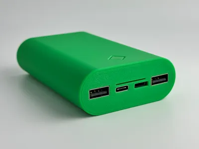
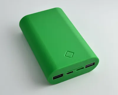
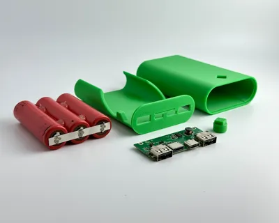
This is a 3-cell power bank I designed for some 18650 cells. The cells are wired in parallel. I used 3200mAh cells for a 9600mAh power bank. It has a pushable button that lights up 4 LED's to indicate charge.
Materials Needed
- 3D printed parts (no supports needed. If not using print profile, print with at least 3 walls)
- 20AWG stranded wire. Amazon Link
- Charging Module. Amazon Link
- Optional: Kapton Tape to protect 18650 cells from short circuit. Amazon Link
- Hot Glue/superglue/epoxy
Tools Used
- Spot Welder (for batteries). Amazon Link
- Nickel Strips. Amazon Link
- Soldering Iron. Amazon Link
- Hot Glue Gun
Assembly
I printed mine with PETG-HF. I have not tried any other filament. PLA should work as well, but tolerances are probably too tight for a Carbon Fiber or Glass Fiber filament. If using a different filament (PLA, ABS, ASA), let me know if tolerances need to be tweaked for you, and I can upload a print profile.
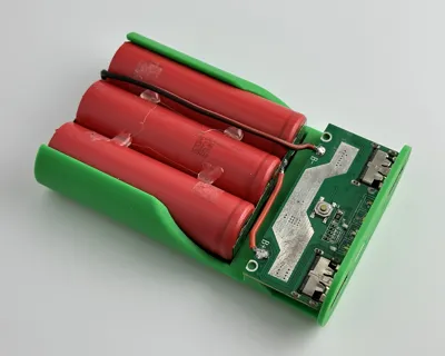
I placed the 3 cells in the carriage and then hot glued them together (on both sides). Once glued, I removed the cells and then spot welded them together in parallel with nickel strips. (Parallel = all (+) together and all (-) together).
I used 20AWG stranded wire and soldered the black wire to the nickel strip on the (-) end and the red wire to the nickel strip on the (+) end.
Then solder the other end of the wire to the appropriate spot on the charging module (B- and B+). You can add Kapton tape over the nickel strips to protect them from short circuit. It's not shown very well in my images but make sure your back wire is NOT resting on the nickel strip as it crosses over to the module. Route and glue the wire to the battery so it can't come in contact with the nickel strip.
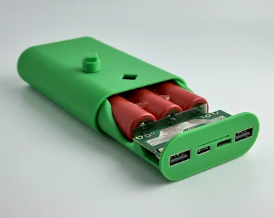
Slide charging module into position (LED lights facing up). I superglued the module in place onto the carriage. You could also drill little holes and attach with small screws.
To assemble, start with a practice assembly - start sliding the carriage into the case. Before the LED button (on the module) goes into the case, set the 3d printed button on the module and push it into place (as you slide the carriage in). You will need a tweezers or toothpick to position it. Once It's in the right position, flip the case upside down so the button “falls” into place. Then you can finish pushing in the carriage all the way into the case. The button should click. Once you confirm everything fits as it should, take it apart. Add some glue (superglue or epoxy) to the inside of the case (where carriage touches). Also add a very small amount of glue around the lip of the case where the front of the carriage rests. Carefully assemble and let the glue set. Congrats! All DONE!
This is my first time designing something like this - so if you have any suggestions on how to make this model better, let me know! I'd love some feedback!
License
You shall not share, sub-license, sell, rent, host, transfer, or distribute in any way the digital or 3D printed versions of this object, nor any other derivative work of this object in its digital or physical format (including - but not limited to - remixes of this object, and hosting on other digital platforms). The objects may not be used without permission in any way whatsoever in which you charge money, or collect fees.
Comment & Rating (53)