
Rtx 5090 Spinning Fans 3:4 Scale
Print Profile(2)





Description
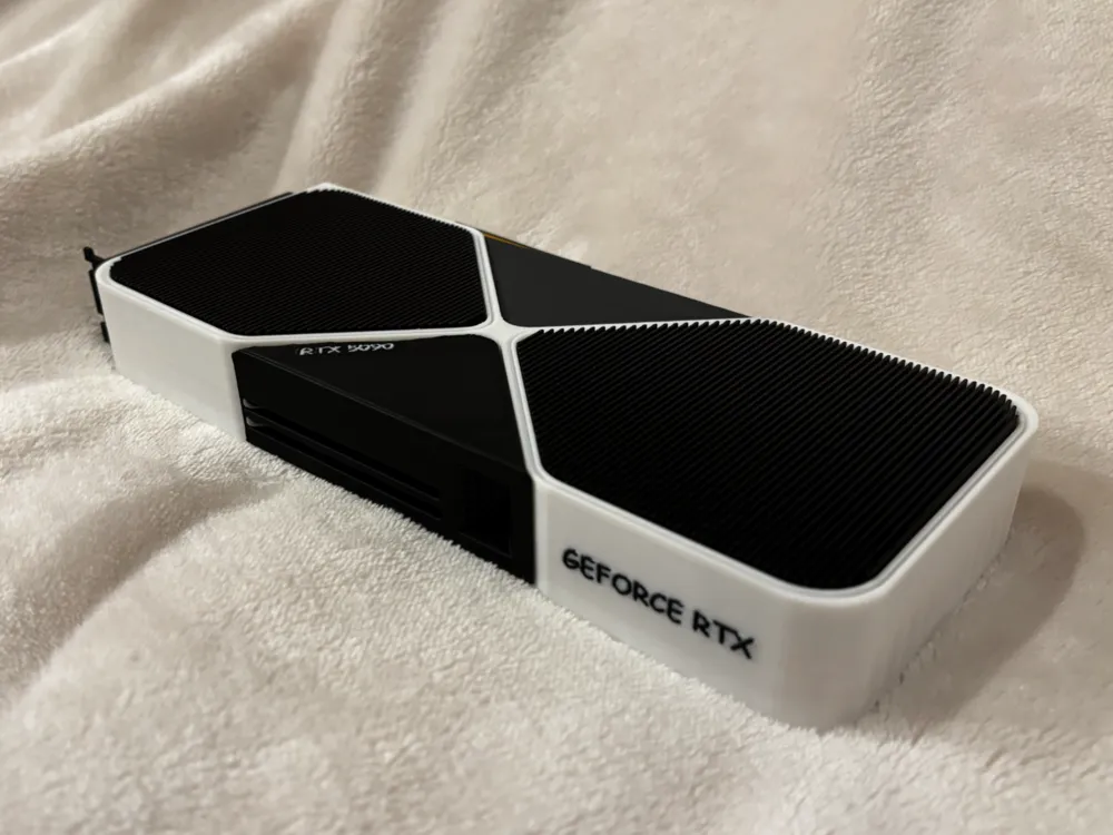
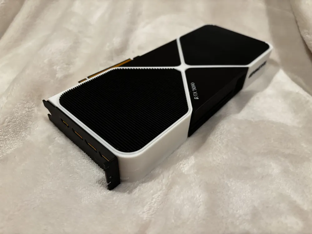
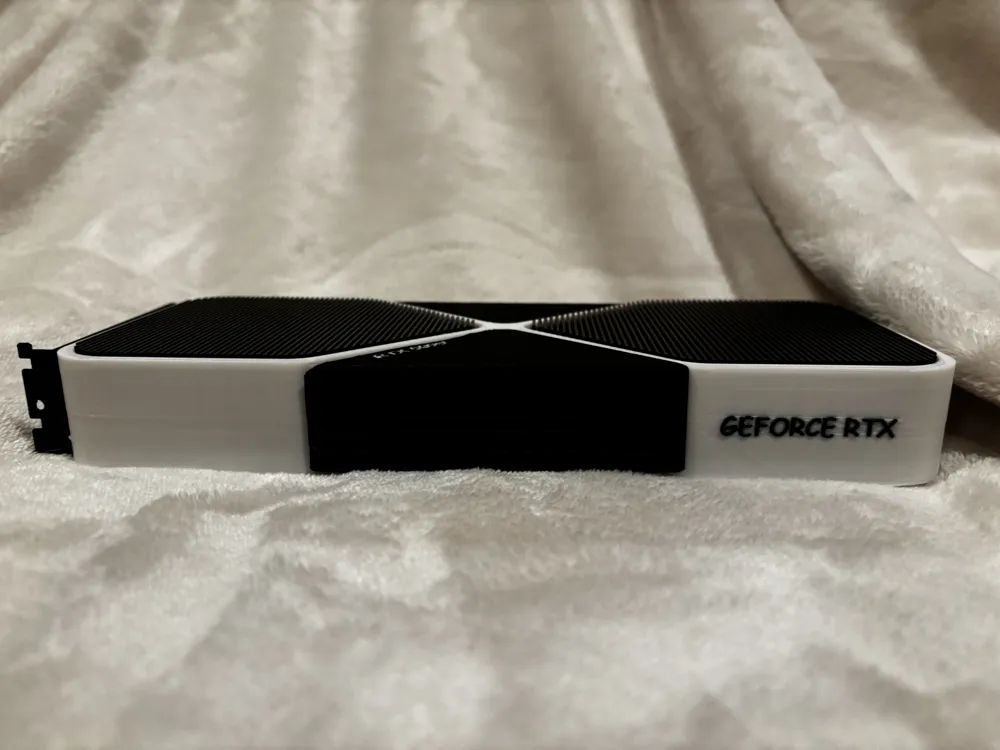
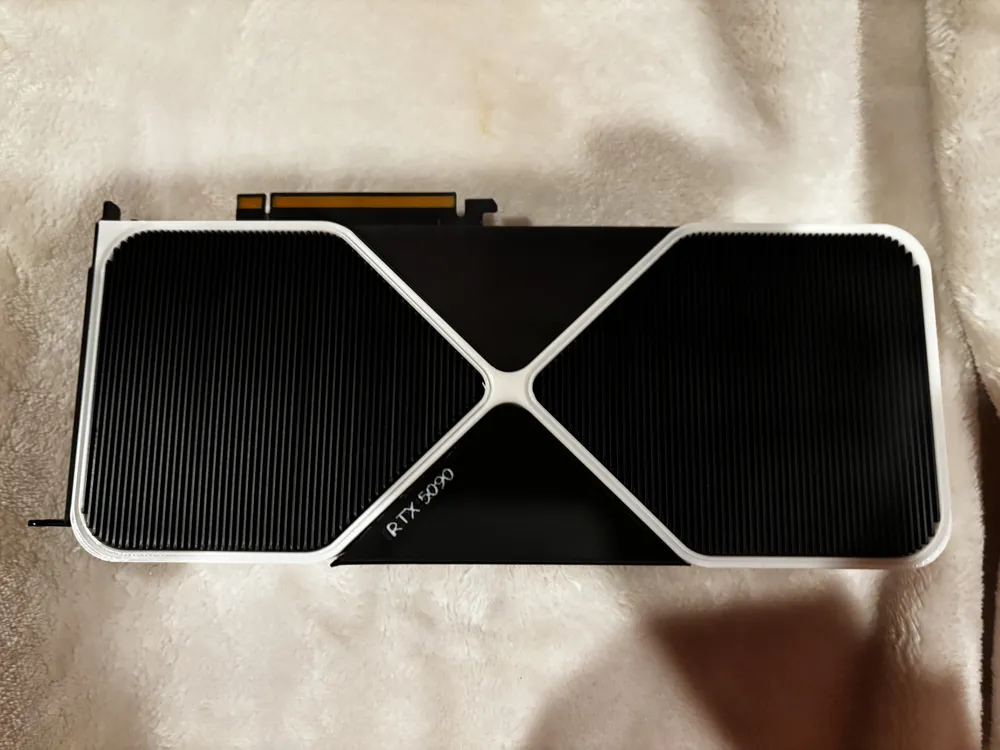
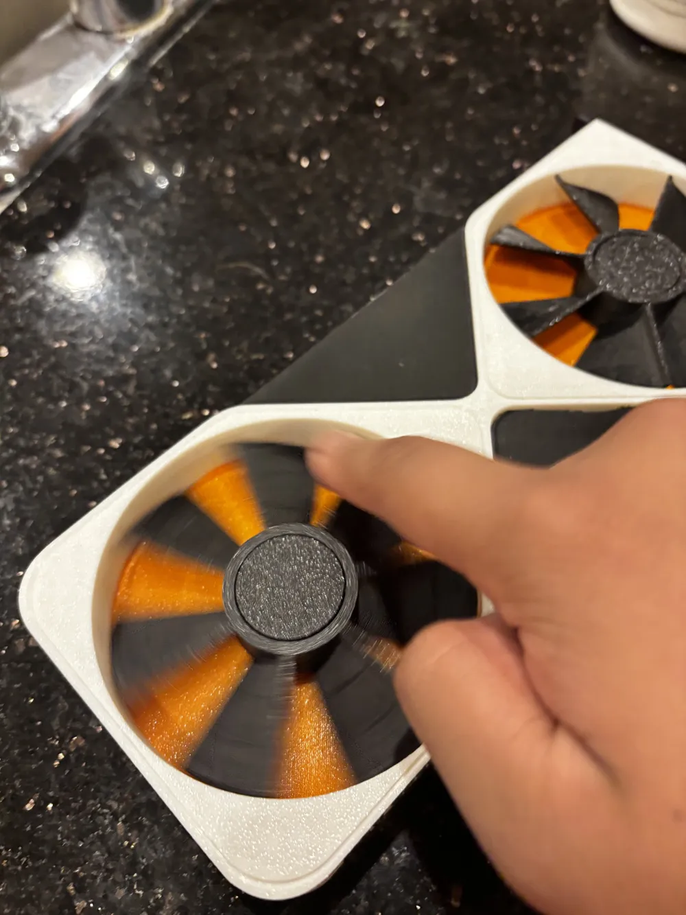
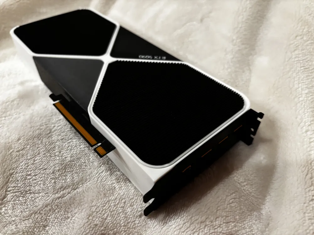
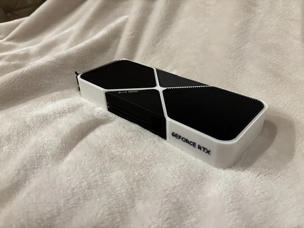
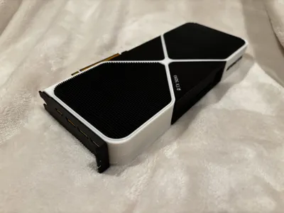
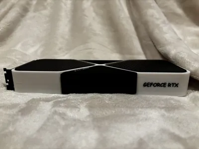
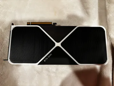
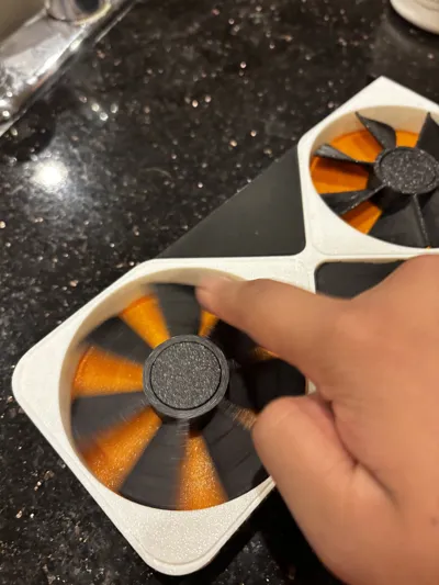
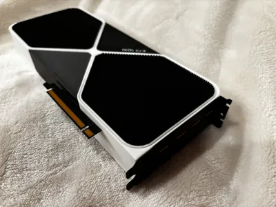
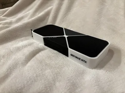
This is a 3:4 (75%) scale of the 5090 Founder's Edition. It is almost exactly accurate because reference images were used to create this. It even has the 12VHPWR connector and the exact number of heat fins as the real 5090. Please scale down the model at your own risk as the gap between the fan's rings becomes smaller and it may not spin properly. FYI, the area underneath the fan in the photos is orange because i ran out of black filament and had to switch. Yours will be the same color as the heatsink. Feel free to check out my other models. I don't have many right now, but I'm trying to expand! All boosts, comments, likes, downloads, etc. are very much appreciated thanks. Please see assembly guide below.
Boost Me (for free)
If you liked this model, please consider giving it a boost. It's free for you but helps me out in ways you can't imagine. Thanks!
Assembly Guide
With the frame facing up, apply glue (I used hot glue) to area outside the circular cutout. Then place the 2 heatsinks inside. Flip the frame over. Apply a small amount of glue only on the center of the fan (do not glue the outside ring otherwise the fan won't spin). Carefully place the fan in the center of the bottom of the heatsink. Ensure there is a small gap between the ends of the blades and the outside of the cylinder so the fan spins better. Repeat for the other fan. Now place the frame back normally facing up. Put glue in the front triangular cutout and place the triangular piece with the 2 holes and the power connecter. Align the two black parts on the frame with the triangular piece. The triangular piece should not be level with the top or bottom of the frame as it is shorter, like in the real 5090. Take the other triangular piece and rotate the frame to the back. Note the small rectangular hole on the long face of the second triangular piece. Make sure this piece goes to the top right when glued. Glue it in the same way as the first triangular piece except this time there are no long holes. Try to place it in the middle of the frame height wise. Next, take the PCIe connector and insert it into the hole on the second triangular piece. I did not use glue for this step but if yours falls out a lot, I would highly recommend to. Lastly, rotate the frame so you are facing the left of it. Take the PCIe bracket at place it so that the right side of it is where the curve on the frame becomes flat. Glue this part and you should be all done. Hope it turned out great for you!
License

You shall not share, sub-license, sell, rent, host, transfer, or distribute in any way the digital or 3D printed versions of this object, nor any other derivative work of this object in its digital or physical format (including - but not limited to - remixes of this object, and hosting on other digital platforms). The objects may not be used without permission in any way whatsoever in which you charge money, or collect fees.


Comment & Rating (21)