


Print Profile(3)


Description
The model was updated to V2 on 28.4.2026. The V2 update brings a lot of new customization features for an even nicer strain relief model.
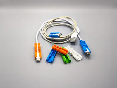
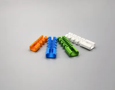
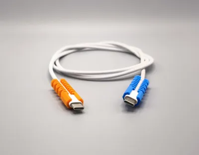
A parametric strain relief generator for all of your cable strain relief needs.
No more searching for a design, now you can easily generate one yourself with just a few inputs and clicks.
Works with all materials. For durability, I recommend using PETG.
Extremely easy to use. Simply remove the brim (if used), press in the cable all the way, and pull back so the connector is properly seated in the connector opening.
Play around with various parameter values and see the result.
Please read the parameter description below.
Boost Me (for free)
If you find the model useful, consider a boost. It is completely free to do. Thank you for your support.
Parameters
- wire_diameter - spring section hole diameter for cable in [mm]
- connector_width - connector width in [mm]
- connector_height - connector height in [mm]
- connector_radius - connector corner radius in [mm]
- connector_length - connector length you want to have embedded in the strain relief in [mm]; usually shorter than the actual connector length
- max_length - maximum total length of the model in [mm]; actual length may be shorter and depends on other parameters
- end_length - end block length in [mm]
- spring_size - gap between spring elements in [mm]
- spring_thickness - spring wall thickness in [mm]
- wire_opening - opening for wire insertion as a ratio of “wire_diameter” parameter [0-1]
- connector_opening - opening for connector insertion as a ratio of “connector_width ” parameter [0-1]
- chamfer - chamfer size in [mm]
- vertical_material - vertical material thickness in [mm]
- horizontal_material - horizontal material thickness in [mm]
Parameters notes
Some parameters have limits on min/max values. Some parameter min values depend on other parameters. This is to ensure the model generates correctly. Here are a few such parameters:
- connector_radius - limited by “connector_width” or “connector_height”, whichever is less
- max_length - you only set the maximum length the model can't exceed, actual length will likely be less and will depend on multiple other parameters like “connector_length”, “end_length”, “spring_size”, “spring_thickness”.
If using the chamfer, increase the wall thickness. Chamfering the edges removes some material and makes the model weaker / more flexible. Compensate by increasing the “spring_thickness ” parameter value.
If you want a circular hole for the connector portions as well, simply set “connector_width” = “connector_height” and "connector_radius" to half of that value.
Parameter “connector_length” is usually slightly shorter than the connector plastic enclosure. Check where the connector needs to plug in to and account for any limits. I usually set this to 2mm less than the connector enclosure length.
Parameter “spring_size” determines the spring section inner radius. Decreasing this value will fit more spring sections in the same length. This impacts the force required to bend the model and the bend radius.
With small-diameter cables, like a phone charging cable, I recommend keeping this value low at 1 - 3 mm.
Parameter “spring_thickness” determines the spring wall thickness. Decreasing this value will fit more spring sections in the same length. This impacts the force required to bend the model. Thinner walls are more easily bent. The value depends on the material used.
Parameters “wire_opening” and “connector_opening” are set as a ratio calculated based on “wire_diameter” and “connector_width”. You are limited to values between [0.1 - 0.9] (10% to 90%).
Larger values increase the opening size, making cable insertion easier, but decrease the holding strength.
About 0.7 (70%) seems like a good starting point if you are unsure where to start.
The value will depend on the material you use. Harder materials will require a larger value.
Printing tips
- When printing, make sure you set the wall loops parameter high enough so that the spring sections do not have infill.
- Account for material shrinkage. In general, I add 0.1 mm to my measurements.
- For 0.4 mm nozzle, I recommend using “0.16 mm high quality” profile for best results. Go slower if possible.
- Use brim and ensure your print bed is properly cleaned and prepared. Unless you are absolutely confident in your print bed adhesion, that is.
- The model works with all filaments. Parameter values will depend on the filament used.
PLA is easiest to print but not as durable.
PETG is recommended for durability.
TPU may be too soft unless you use something of higher hardness, like TPU for AMS, for example.
Nylon or ABS/ASA will also work well, but they are more difficult to print.
License
You shall not share, sub-license, sell, rent, host, transfer, or distribute in any way the digital or 3D printed versions of this object, nor any other derivative work of this object in its digital or physical format (including - but not limited to - remixes of this object, and hosting on other digital platforms). The objects may not be used without permission in any way whatsoever in which you charge money, or collect fees.
Comment & Rating (159)