

29mm Jet Fan
Print Profile(3)


Description
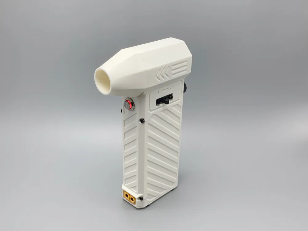
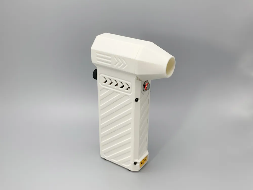
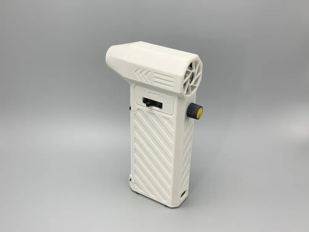
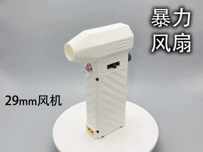
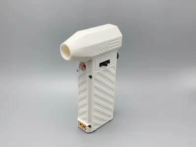
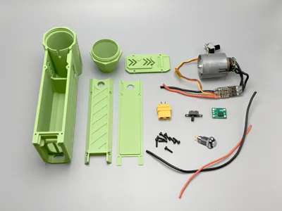
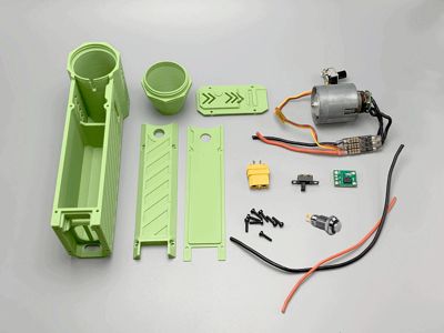
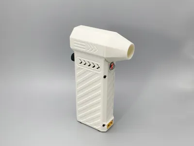
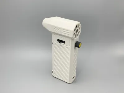
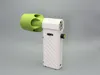
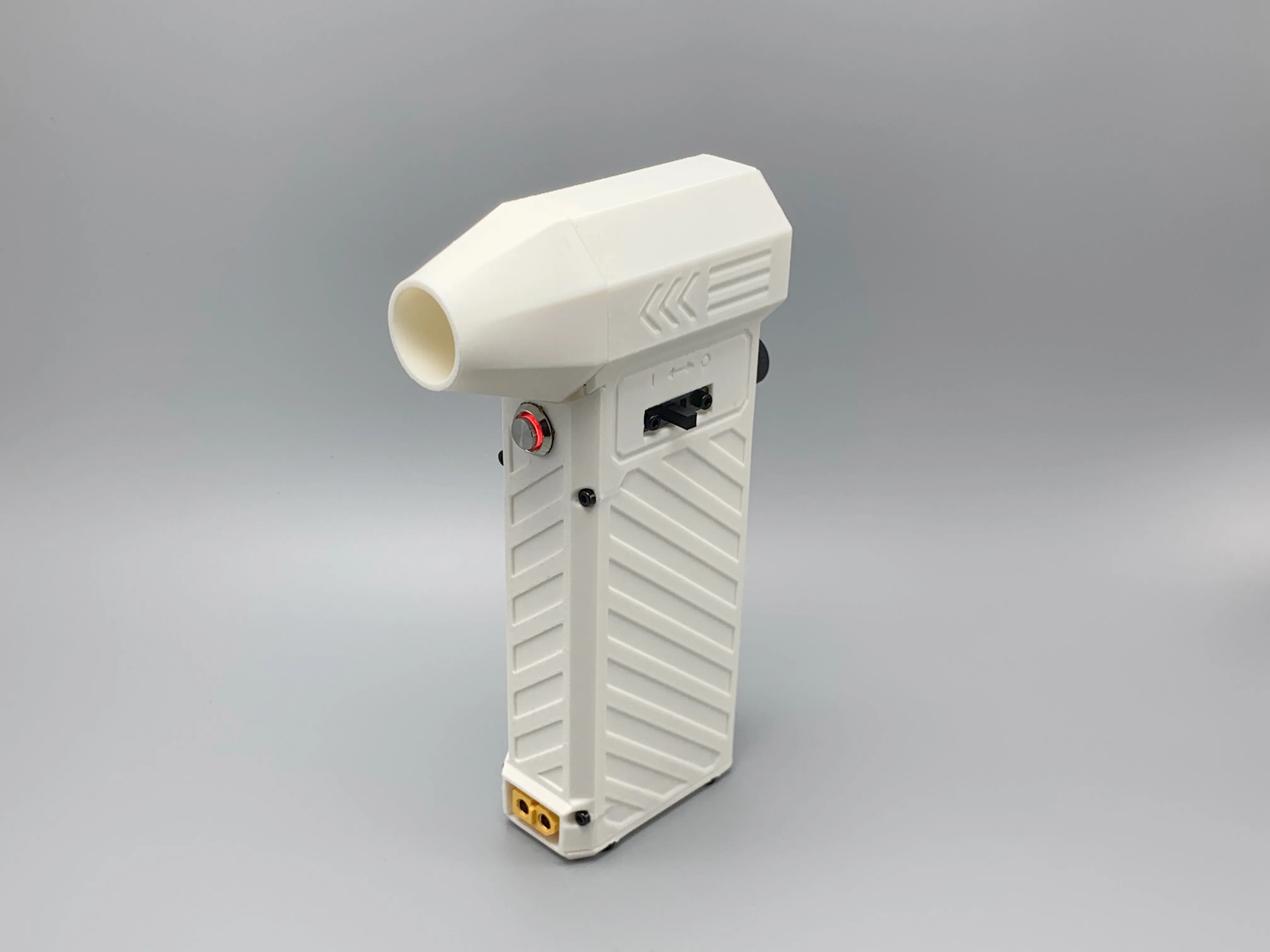
This model is a handheld high-power fan with a 29mm fan, using two 21700 batteries. Its optimized structure requires no magnets, offering an excellent feel
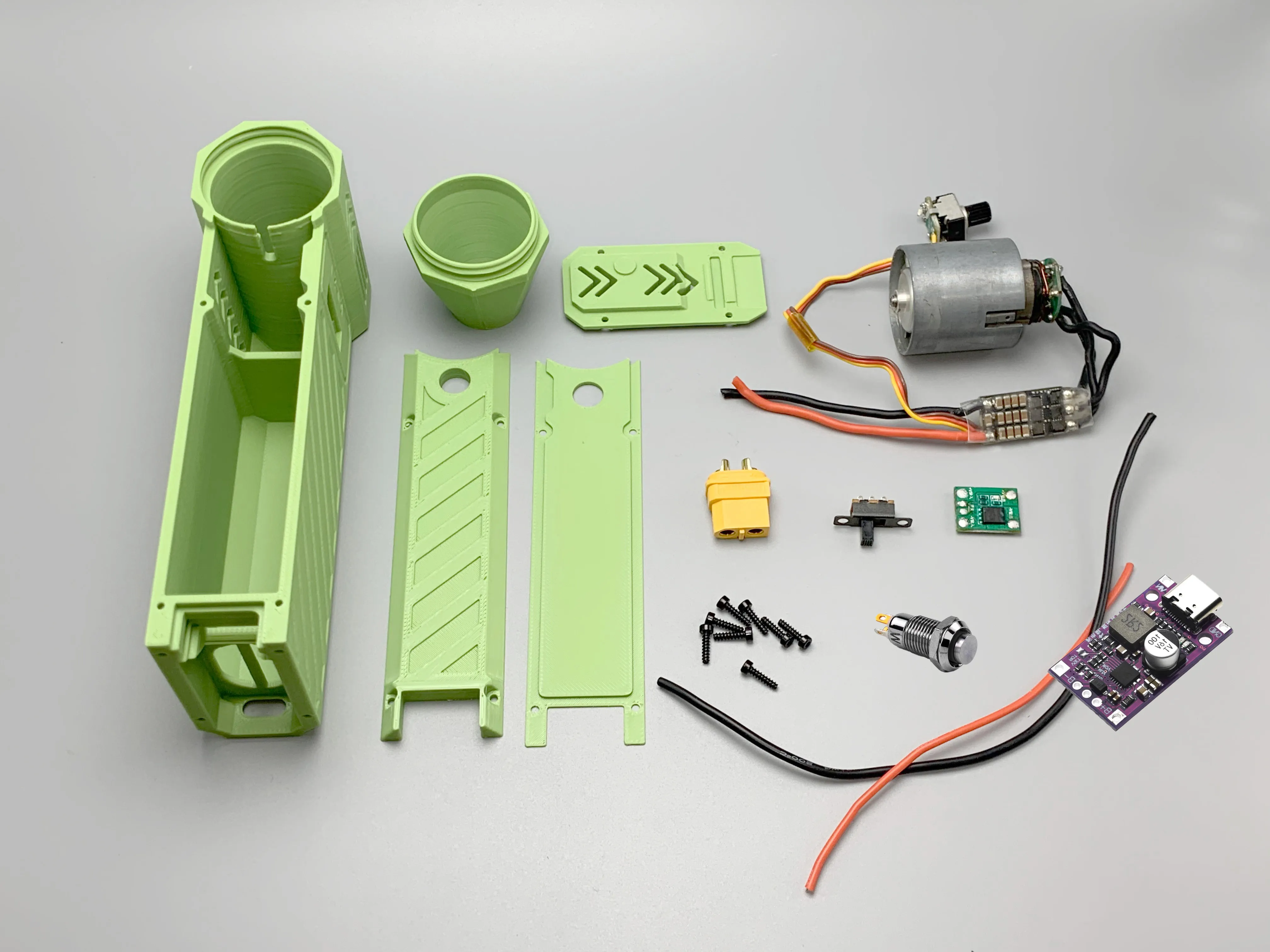
Features:
- Fast and easy printing, requiring only 63g of ABS filament
- Side-opening cover provides ample operating space for smoother installation
- Fewer overall components, print-in-place design, with optimized printing direction
- Added XT60 connector (male and female compatible), allowing for unlimited runtime when connected to a charger
- Compact design with short connection wires for high space utilization, requires hands-on ability for assembly
- Magnet-free design with threaded outlet installation for stability and reliability
- Fully sealed, rounded air duct reduces air volume loss and noise
- Circuit wired for one-button high power, expandable for other uses

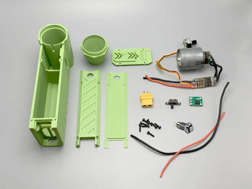

Materials:

- 29mm high-power fan (many options online, or you can wind your own; choose between external or integrated ESC)
- 21700 battery with 10C or higher (I use Sony VTC6A)
- ESC: https://item.taobao.com/item.htm?id=703030956908&sku_properties=31309%3A23608095307&spm=tbpc.boughtlist.suborder_itemtitle.1.54be2e8dlw6mFF
- 50A MOS board: https://item.taobao.com/item.htm?id=756235387248&skuId=5386403159031&spm=tbpc.boughtlist.suborder_itemtitle.1.54be2e8dlw6mFF
- Charging board (must be purple PCB): https://item.taobao.com/item.htm?abbucket=13&id=751292213837&mi_id=cBAgCZFyXHHfxSW8yKnUjKd25ZUJj4ctyNwRdfrLJ-jNZDdFjoHXnlG_tstzENYJF1lSfWFgFqxCJnJRoiNFhtS_50OecTjSRnEvD5i1Od4&ns=1&priceTId=2147828617549225956095931e1a4b&skuId=5178645192275&spm=a21n57.1.hoverItem.16&utparam=%7B%22aplus_abtest%22%3A%221d6ef75cea4d7c3b4d52e651f6ab6797%22%7D&xxc=taobaoSearch
- Button (8mm high head with light, self-resetting; 3-24V): https://item.taobao.com/item.htm?id=673518560555&spm=tbpc.boughtlist.suborder_itemtitle.1.54be2e8dlw6mFF
- XT60H-F (XT60H-M also acceptable): https://item.taobao.com/item.htm?id=618920756271&spm=tbpc.boughtlist.suborder_itemtitle.1.54be2e8dlw6mFF
- Toggle switch: https://item.taobao.com/item.htm?id=661782612160&skuId=4773260288180&spm=tbpc.boughtlist.suborder_itemtitle.1.54be2e8dlw6mFF
- M2*8 self-tapping screws x10 (M2*8 (100 pieces) black): https://detail.tmall.com/item.htm?id=600255824864&spm=tbpc.boughtlist.suborder_itemtitle.1.54be2e8dlw6mFF
- Sufficient soft silicone wire (do not use hard wire). Power wires should withstand 20A current; signal wires should be as thin as possible
Usage Notes:
*Batteries and circuit boards risk heat accumulation during use; do not run at maximum power for extended periods
*Do not charge or connect Type-C and XT60 interfaces simultaneously to prevent common-source backflow damage to the circuit board and charger
*The XT60 interface can draw power and also charge with an 8.4V charger, but never connect it to a battery pack (even with the same series count; parallel connecting batteries of different voltages is equivalent to a short circuit and is extremely dangerous)
*Turn off the main switch after use to prevent battery over-discharge. If the fan speed significantly decreases or makes abnormal noises during use, the voltage is too low and requires charging
*Do not place any body part near the air inlet during use to avoid danger
*Significant heat will be generated during use; please print this with ABS/PETG
Assembly Notes:
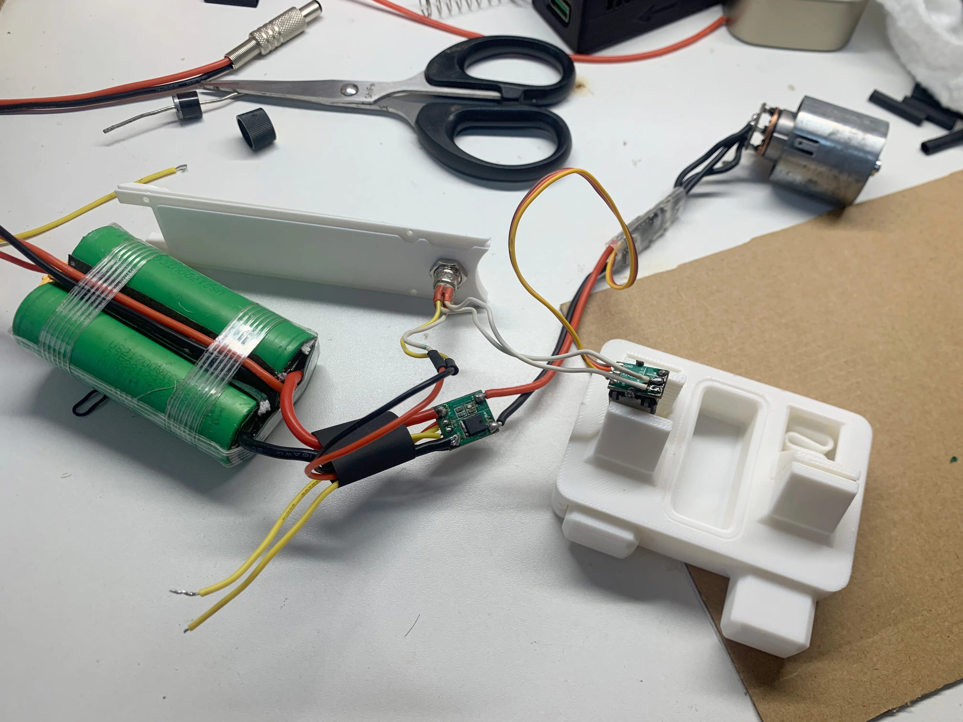
1. Connect the wires as follows:
- Cover all exposed wiring parts with heat shrink tubing to prevent short circuits. Use thin wires that are as short as possible to easily fit them into the casing
- Main power wire (battery - MOS board - ESC - fan)
- Metal button (switch wire connects to the ESC's one-button high-power contact, and the light wire connects to the MOS output contact, parallel to the ESC main wire)
- Route the MOS board switch wire using a thin wire to connect to the main switch later
2.
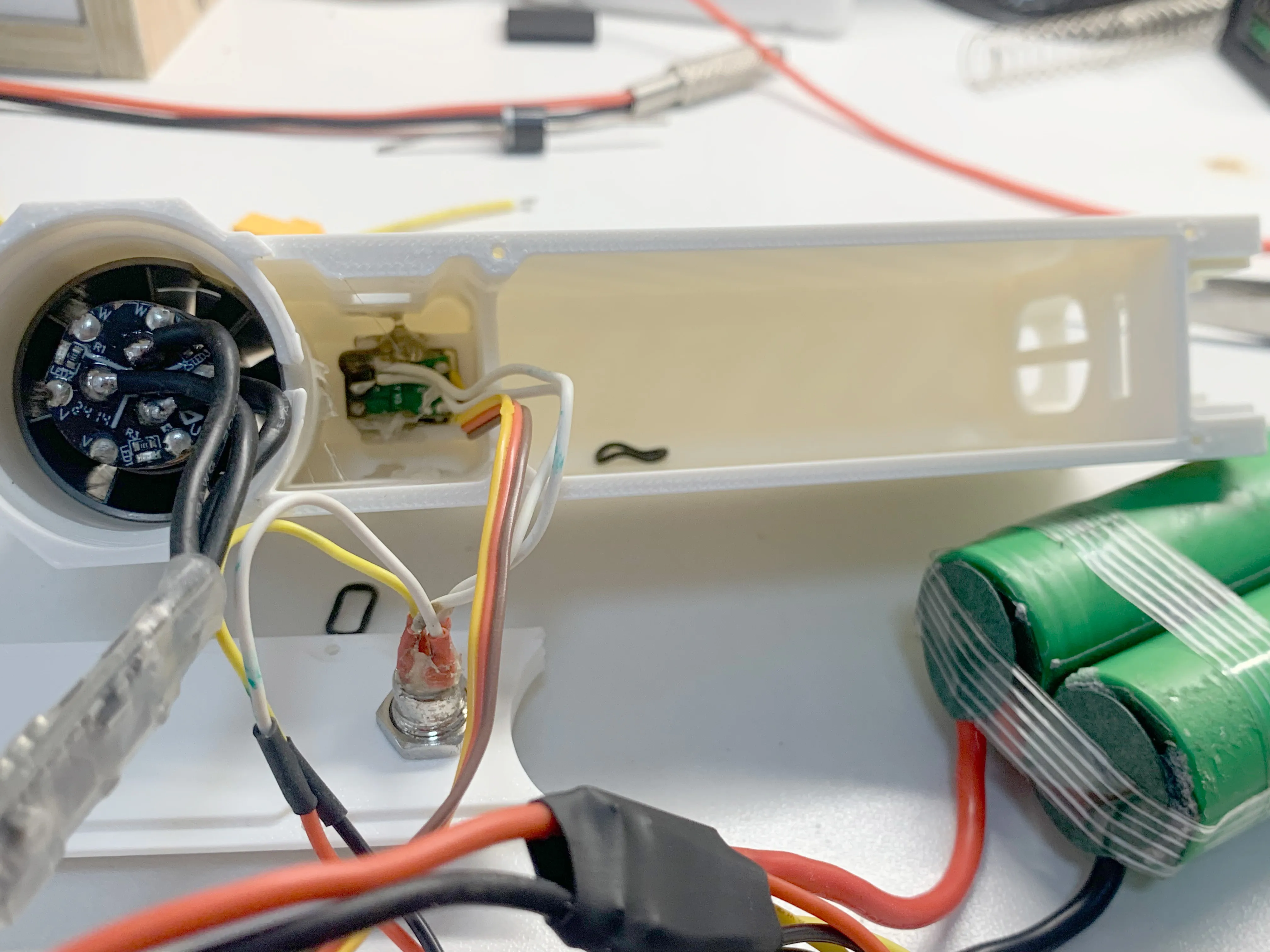
- Insert the ESC into the interior and lightly secure it with a small amount of hot melt glue or silicone to prevent it from coming loose, then install the knob
- Place the fan into the casing; if it's too loose, you can secure a piece of electrical tape to the outside of the fan to reduce wobbling
3.
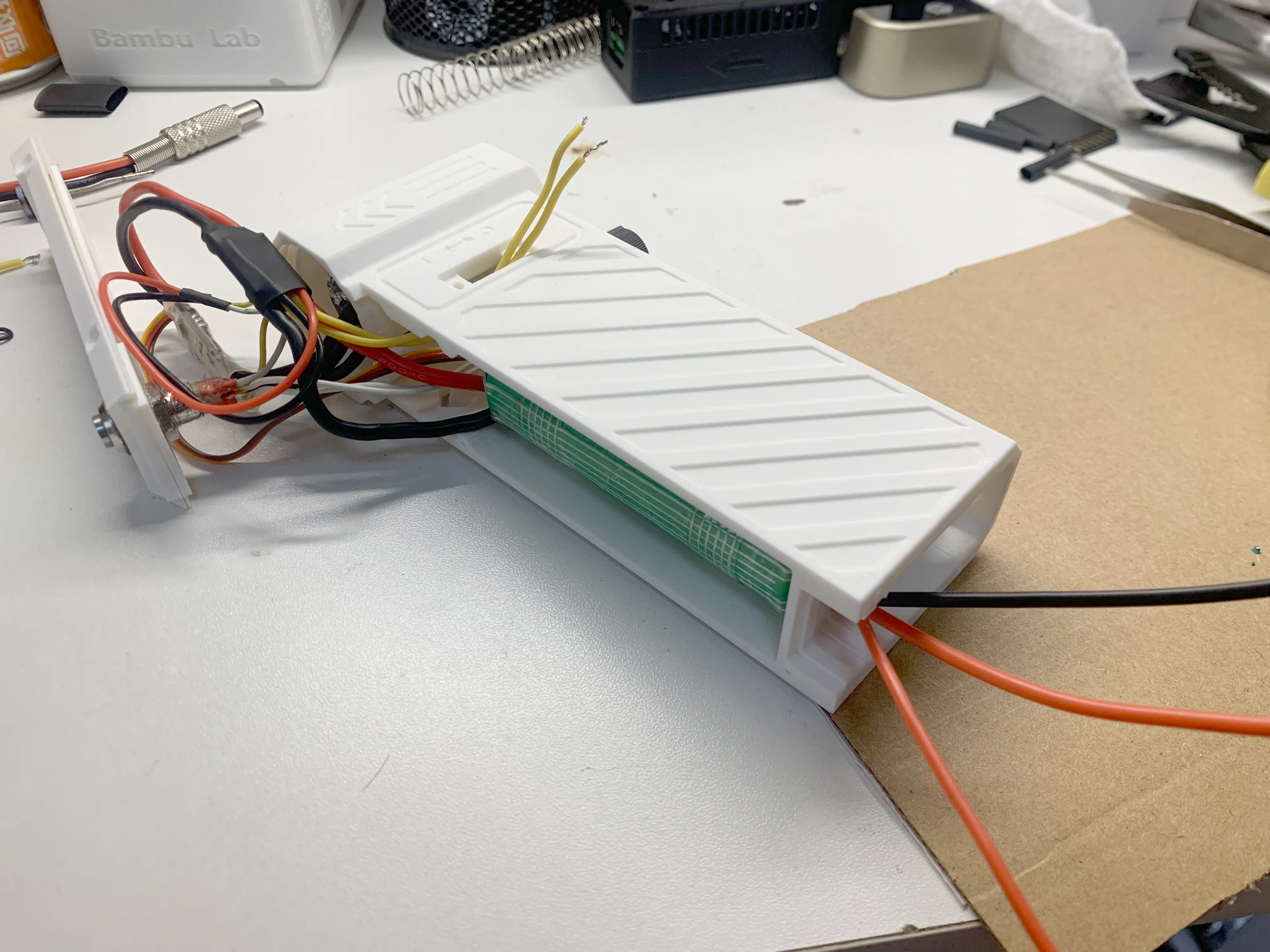
- Place the battery in the center. Pass the three charging wires through the square hole at the rear. Route the main switch wire from the hole at the top, preparing to insert the connecting wires and circuit board
4.
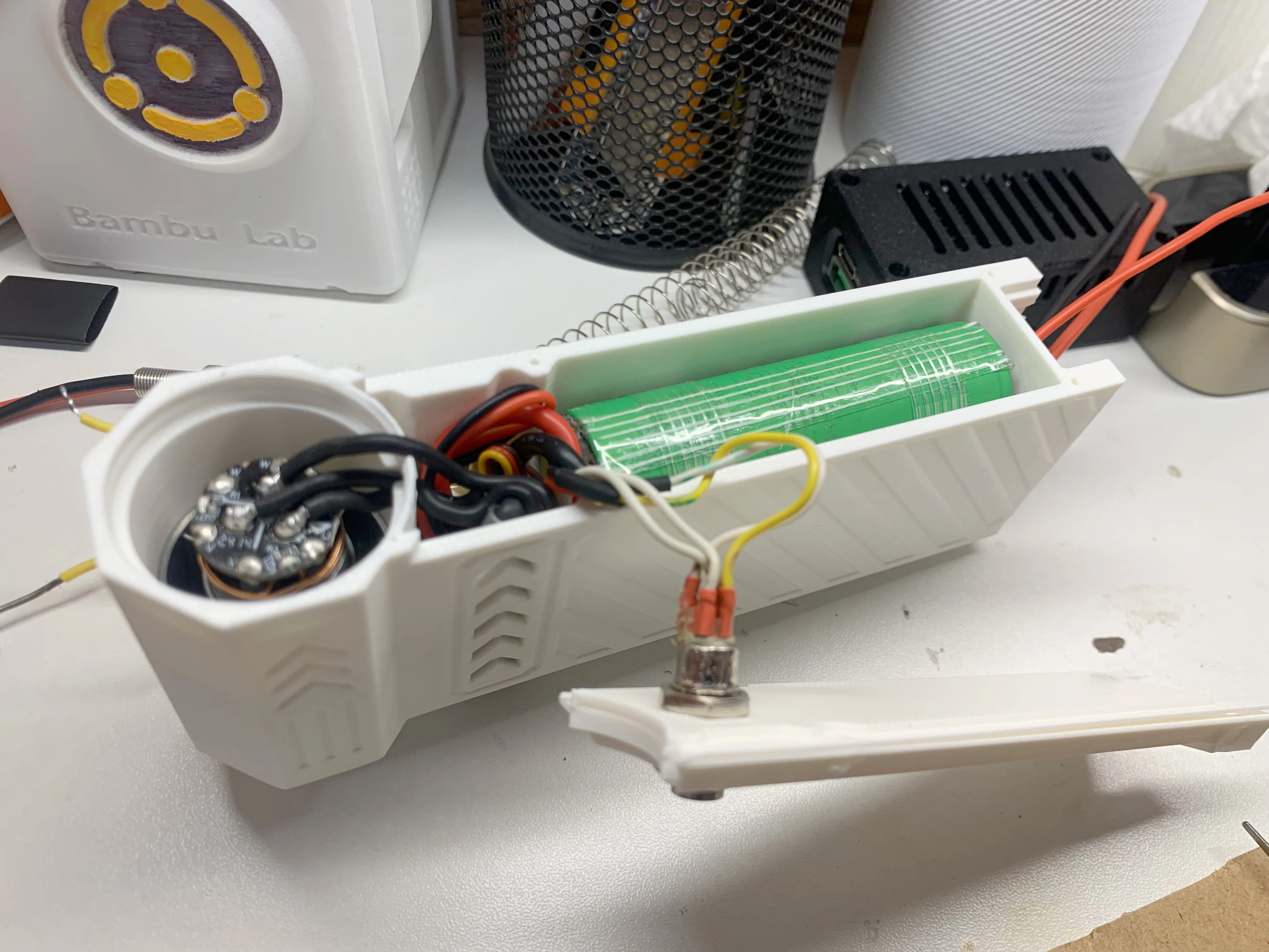
- Insert the ESC, MOS board, wires, etc., into the interior (my connecting wires were long, making this difficult; I recommend optimizing wire length)
- Create a hollow space in the middle with your finger to allow the metal button to fit smoothly
- Check if the battery wobbles; if so, you can use some tape to secure it
5.
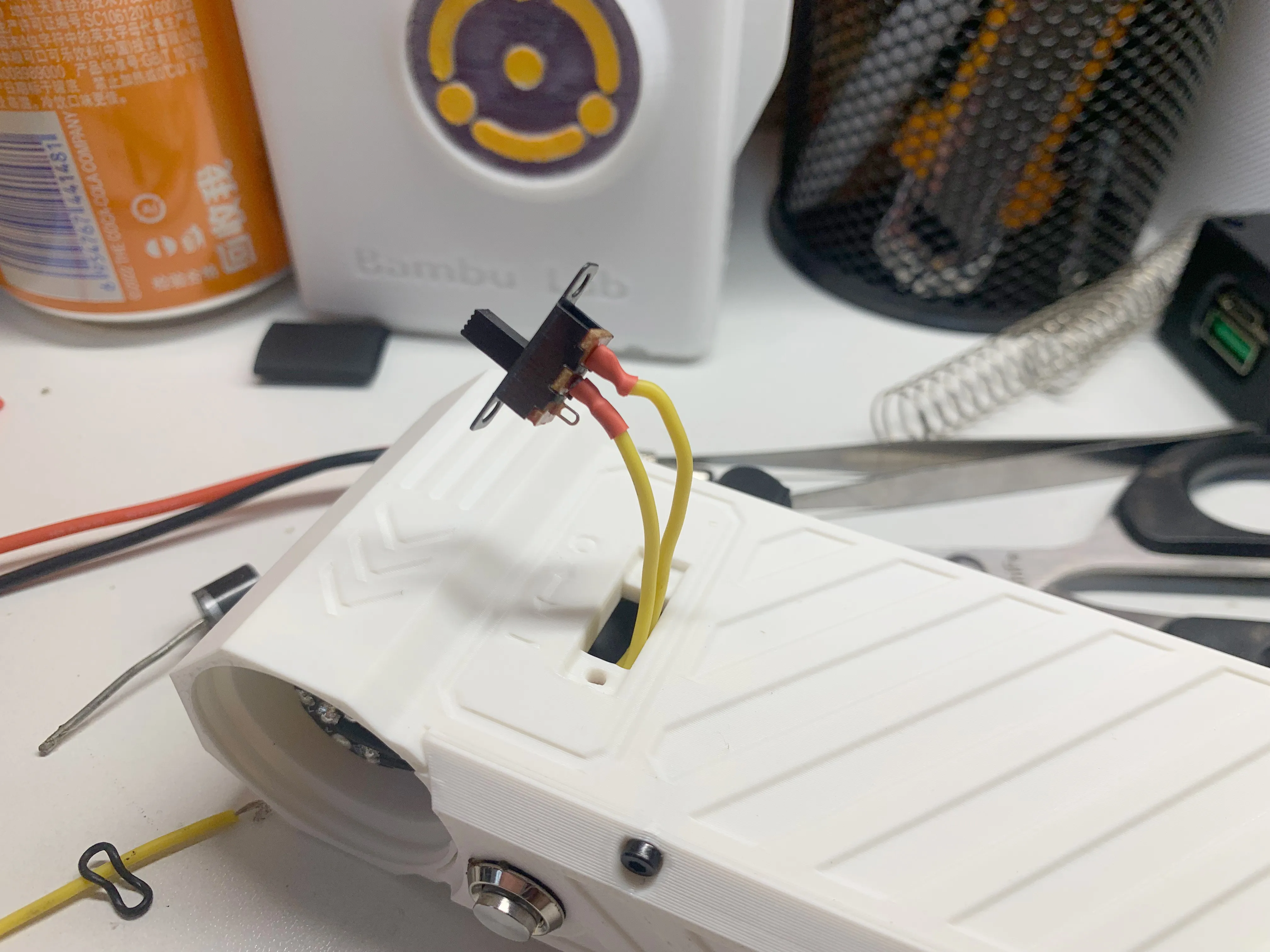
- Secure the front cover with screws, solder the main switch, and cover it with heat shrink tubing
- For the main switch securing screws, since the 2x8 self-tapping screws are long, use pliers or a grinding wheel to shorten their length to 3-5mm to prevent piercing internal cables. Alternatively, you can tidy up the internal wiring through the holes without grinding the screws
6.
- Check if the switch and fan operate normally. Next, begin installing the charging board and XT60 connector
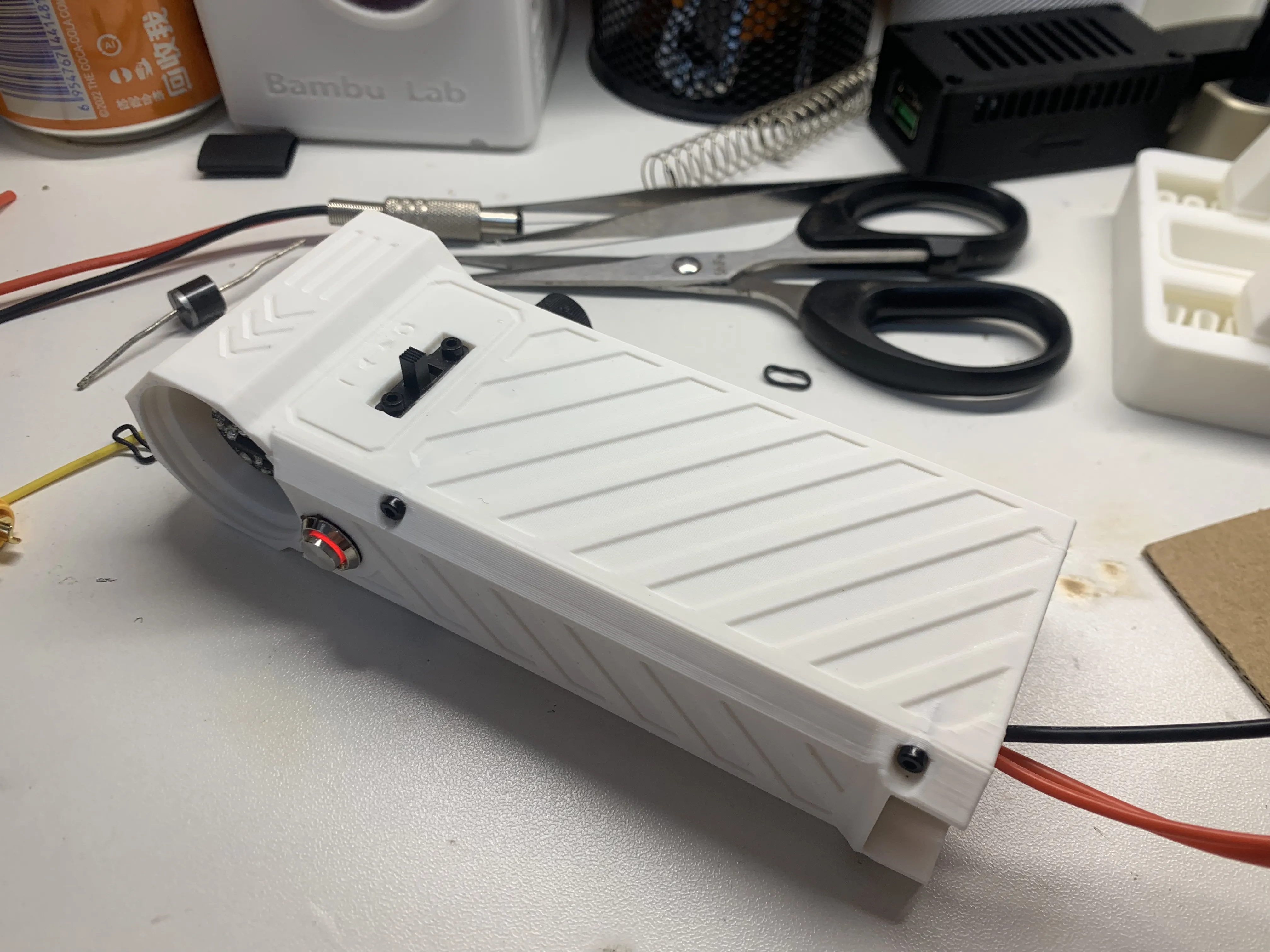
7.
- Cut the outgoing wires (as short as possible)
- Sequence: Battery positive/negative - XT60 - Charging board (bend charging board wiring 90°). Solder the balance wire in the middle of the charging board
- Special attention: Absolutely do not let positive and negative terminals touch during soldering, and prevent the soldering iron from short-circuiting them. Pay close attention to polarity
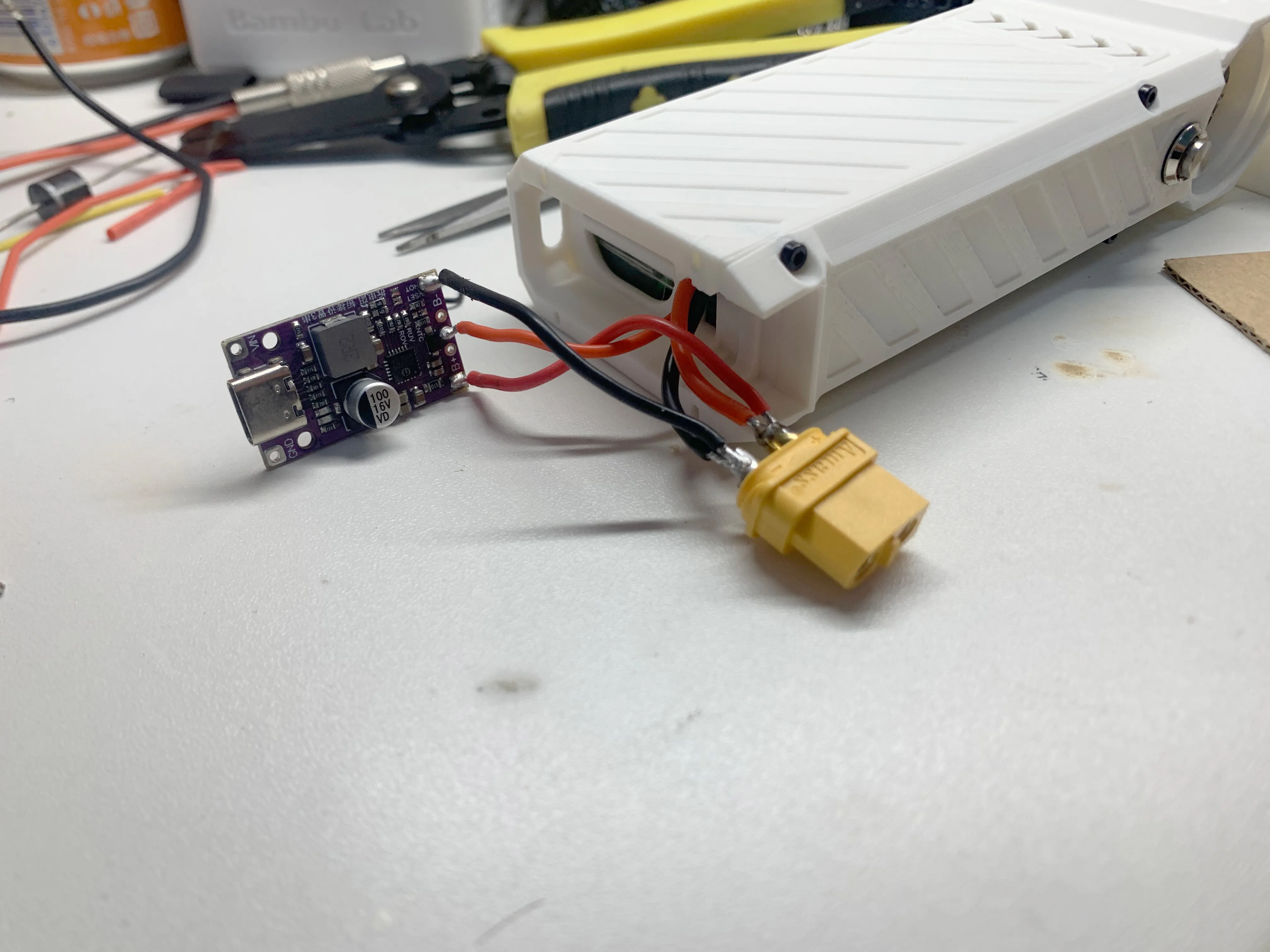
8.
- Place the charging board and XT60 into their respective slots (pay attention to orientation; the XT60 sides differ, so reversing it will not fit perfectly). The charging board does not need trimming; the bottom cover contacts the capacitors on the charging board for stable fixation
- Arrange and tuck in the wires. Ensure the cylindrical capacitor on the charging board remains exposed (the bottom cover contacts the capacitor to secure the charging board)
- The XT60 fits perfectly with the bottom, but given the significant friction during insertion and removal, it is recommended to use 502 super glue to secure both sides to reinforce the connector and prevent deformation or detachment
- After charging testing, cover with the bottom plate and secure with 4 screws
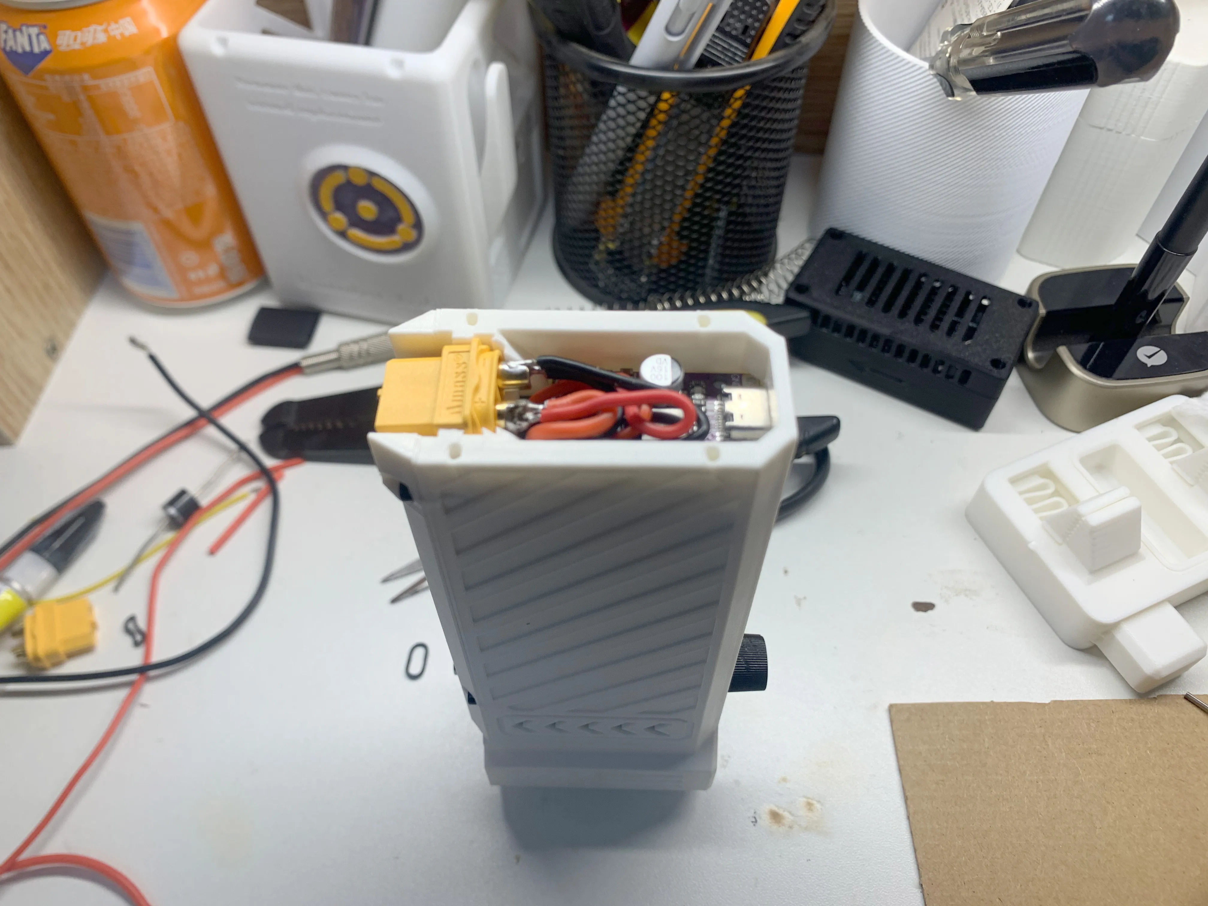
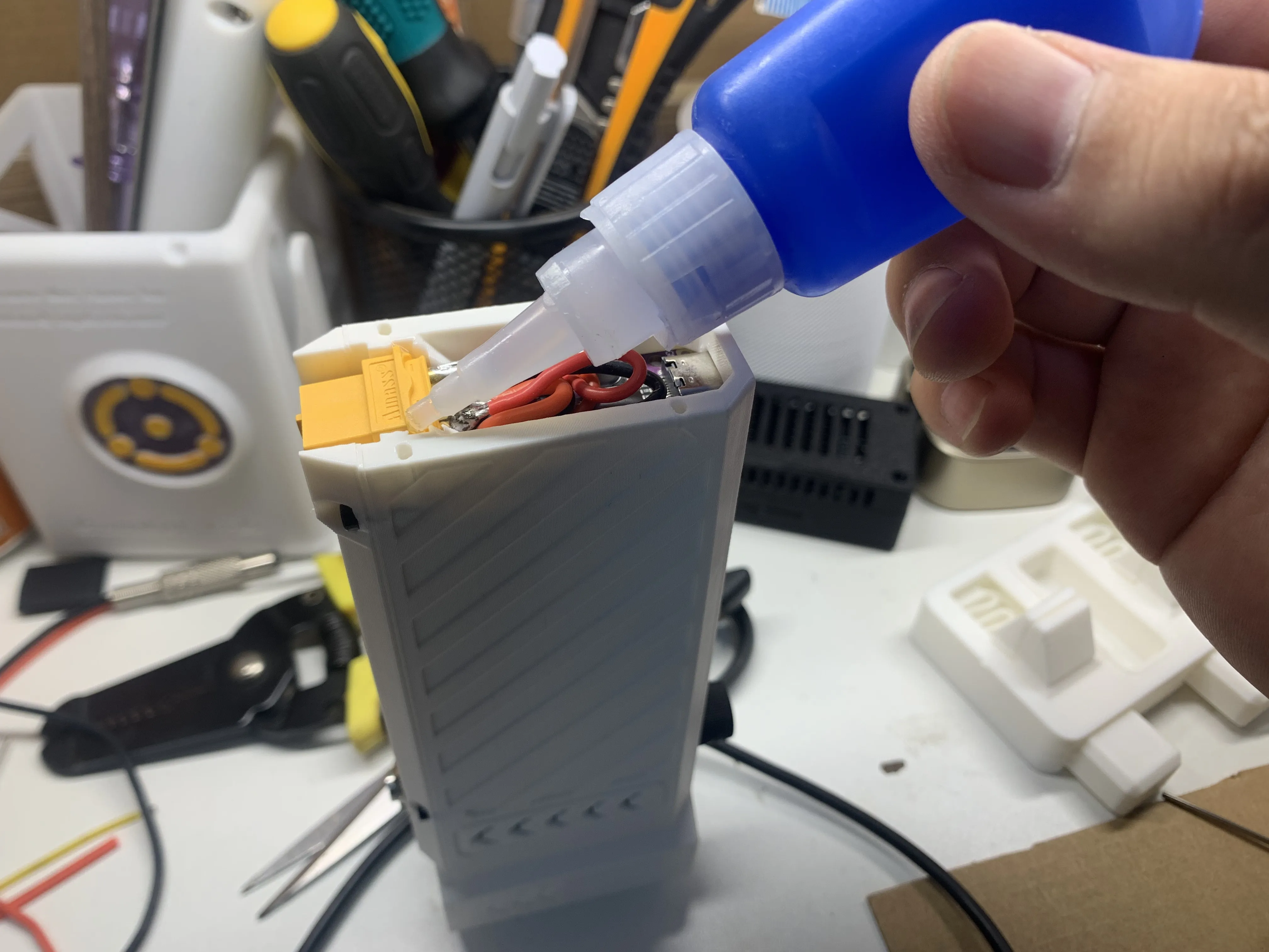
9.
- Screw the air outlet into the main body to complete the installation
*Disclaimer:
- This type of fan is relatively mature on the market, but due to variations in wire, motor, and battery quality, it has high power and rotational speed, carrying risks of damage, injury, battery spontaneous combustion, and circuit spontaneous combustion during use. By printing and using this model, you assume full responsibility for any circumstances related to it
License

You shall not share, sub-license, sell, rent, host, transfer, or distribute in any way the digital or 3D printed versions of this object, nor any other derivative work of this object in its digital or physical format (including - but not limited to - remixes of this object, and hosting on other digital platforms). The objects may not be used without permission in any way whatsoever in which you charge money, or collect fees.


Comment & Rating (63)