Cable Gland for Multiple Cable Diameters


Print Profile(7)


Description
Don’t forget to Like 👍 and Collect 📂 this design so you can easily find it later and support my work!
👉 And don’t hesitate to check out my other creations right here!
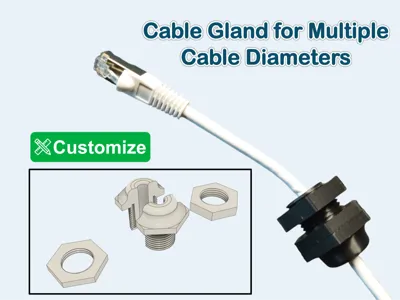
This is a four-piece cable gland designed to securely fasten cables through a panel or control box wall, such as those used on Universal Robots (UR) systems. The assembly consists of a central body that grips the cable, two locking nuts that clamp both halves of the gland, and two optional flat gaskets (24 mm inner diameter, 35 mm outer diameter, 3 mm thickness) to seal against dust and incidental moisture.
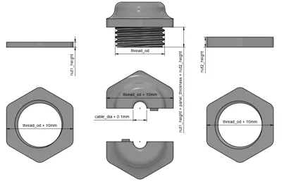
The base model has a thread outer diameter of 35 mm, a thread length of 22 mm, a first nut height of 5 mm, and a second nut height of 8 mm.
Available print profiles:
- For cables with a diameter of 6 mm (base profile).
- For cables with a diameter of 8 mm.
- For cables with a diameter of 9.2 mm, see dimensional drawing in print profile picture.
- For cables with a diameter of 9.525 mm and 13 mm thread length.
- Special slotted nuts for cables whose connector end is too large to pass through the standard threaded bore.
- Two cables of 6 mm and 8 mm in one gland assembly.
- Two cables of 6 mm in one gland assembly.
Three customizable versions are also available:
- Cable gland (single cable): generates the full gland body and both nuts for a single cable passage.
- Cable gland (dual cable): generates the full gland body and both nuts for two cable passages.
- Slotted nuts: generates only the two locking nuts with a slot to allow passage of cables with an oversized connector end. The slot width is generated at cable_dia + 2 mm.
All three customizable models share the same parameters:
- cable_dia — cable outer diameter; the bore is generated at cable_dia + 0.1 mm, and the slot (slotted nut version) at cable_dia + 2 mm.
- thread_od — thread outer diameter; the hex flat-to-flat dimension is thread_od + 10 mm.
- panel_thickness — thickness of the panel the gland passes through.
- nut1_height — height of the front locking nut.
- nut2_height — height of the rear locking nut.
- thread_turns — number of thread turns on both the gland body and the nuts. This value must be identical across all three parts. It must satisfy: thread_turns ≤ (nut1_height + nut2_height + panel_thickness) / 2.


Print settings
The gland body requires supports on the upper cap area only. Supports must not be generated on the threaded section, as they are extremely difficult to remove and would damage the thread geometry.

Boost Me (for free)
🚀 The more boosts I get, the more it motivates me to create new designs and I’ve got plenty of ideas ready to go!
License
You shall not share, sub-license, sell, rent, host, transfer, or distribute in any way the digital or 3D printed versions of this object, nor any other derivative work of this object in its digital or physical format (including - but not limited to - remixes of this object, and hosting on other digital platforms). The objects may not be used without permission in any way whatsoever in which you charge money, or collect fees.
Comment & Rating (59)