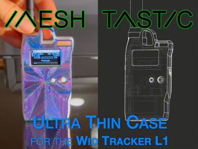
Wio Tracker L1 - Thin Meshtastic Case


Print Profile(2)


Description
Stay connected even when you’re off the grid! The best design for the best new Meshtastic radio– keep it safe and ready for adventure.
- Compact, protective enclosure.
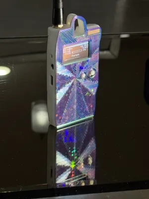
- Thin. Easily fits in your pocket or on your bag.
- Full sized carabiner clip.
- Designed for easy printing (no supports)
The Wio Tracker L1 by Seeed Studio is one of the newest, cheapest, yet most feature-rich Meshtastic devices made yet. Stay in-touch without internet when camping, etc– all open source. The L1 has an OLED, 5 way directional pad (that Meshtastic supports now!), buzzer for notifications, integrated GPS, solar input, extensible sensor port, etc. It's my new favorite board! But it needs a good enclosure!
New: On-Demand Configurator
Make more, most-up-to-date versions with a huge array of configurable options:
- wall size
- battery options (more space for larger batteries, 18350 option, etc)
- special options (like filled-in display for clear resin SLA printing)
- face pattern (like stripes with several different options)
→ Head to my site and check it out! Try different combinations and see 3D rendered previews! ←
Finding one
- Wio Tracker L1 on SeeedStudio site (has in-country warehouse options)
- Seeed Wiki page
- on SeeedStudio's official Aliexpress page
- on Amazon US
Features
So yeah, I spent way too long meticulously modeling and testing to keep the slimmest possible profile– all with
- Full sized carabiner clip support
- Designed to balance upright when hanging
- Maximum GPS reception, up on top with minimal covering
- Wide SMA antenna support (up to 18.6mm diameter)
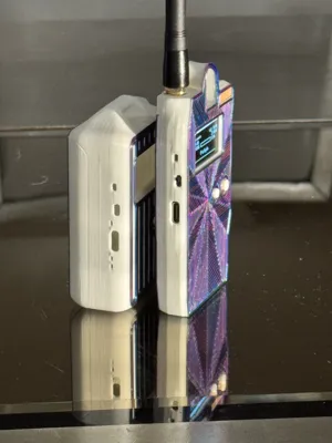
- Accessible USB port (not too recessed to be problematic or too exposed and risky)
- Power switch that's easily moved but not accidentally switched
- Easy navigation with the front buttons
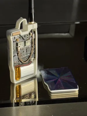
- Easily removable back cover (allows hot swap battery replacements)
- Just 14mm thick in all– just the width of the GPS antenna
Battery Support
It's designed to fit a 750mAh 102535 1S battery cell. There's a maximum area of 10mm depth, 26mm height, 47mm width for other cells.
It's (relatively) easy for me to modify this to fit other cells! Please reach out in my discord [invite link] and say hi and tell me what cell you're interested in fitting.
Printing
Nothing special. Here are my recommended settings:
- Wall-Generator: Arachne (better thin walls. Should be default!)
- Infill: Cubic. 15% if fine. Cubic should be default.
- Walls: 2 is fine.
- Brim type: Mouse Ear (If using Orca Slicer, optional)
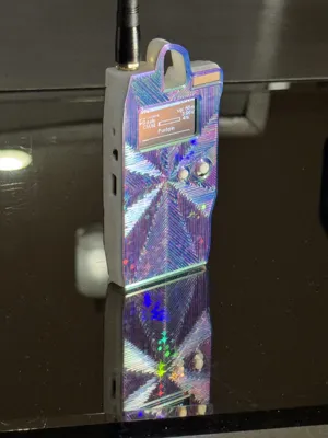
To get the fancy face effect like mine:
- Use a holographic build plate for the multi-color light effects
- Use a tri-color Silk PLA filament to show off the pattern from:
- Use the “Octagram Spiral” Bottom Surface Pattern option in Bambu Studio/Orca
- Use an AMS to swap filaments to print the majority of the body in something stronger like PLA+
Assembly
- Align the display! It's foam-taped into random positions when assembled. It needs to be top-aligned with the main-board.
- User a screw driver to carefully peel up the foam tape from the main-board PCB.
- Align the top of the display with the top of the PCB and re-stick the foam tape. I do this against a right-angled surface like a thick book or a laptop display.
- Loosely install the SMA pigtail into place. Loosely allows the PCB to fit underneath.
- Install the 5-way directional pad cap onto the PCB
- If it doesn't fit easily it's likely due to “elephant's foot” on your first layer. Carefully widen with an xacto knife.
- if it's too loose .. congrats your printer is amazing! Try a dab of hot-glue?
- Install the back button into the recess in the case.
- Install the PCB into position. Lead with the top-right side first.
- Use 4 (minimum of 2) M2 bolts to secure it
- Connect the SMA pigtail U.FL onto the PCB, reorienting the SMA into the case as needed. Add the washers/10mm nut and tighten.
- Slide the GPS into position with the cable coming out through the cutout in the side. Should fit perfectly. Connect the U.FL connector.
- Install your antenna! ALWAYS HAVE THE ANTENNA ATTACHED BEFORE POWERING UP!
- Install and connect the battery.. again, only after installing your antenna.
- Pop on the rear cover. Often easiest with the right side first.
Any questions? Please reach out in my discord! [invite link] I'd like to proactively fix design issues and documentation issues, both! Comments here are okay as well.
Licence
Non-commercial printing for personal use only! Any other uses or redistribution are prohibited. Please reach out in my discord [invite link] if you have any questions.
License
You shall not share, sub-license, sell, rent, host, transfer, or distribute in any way the digital or 3D printed versions of this object, nor any other derivative work of this object in its digital or physical format (including - but not limited to - remixes of this object, and hosting on other digital platforms). The objects may not be used without permission in any way whatsoever in which you charge money, or collect fees.
Comment & Rating (20)