Search models, users, collections, and posts
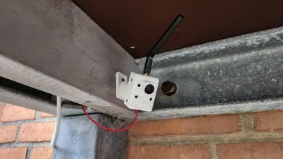
ESP32 Cam Case (Ball Joint mount)
IP Report


Print Profile(2)

0.2mm layer, 3 walls, 15% infill
2.8 h
1 plate
0.2mm layer, 3 walls, 15% infill
1.1 h
1 plate
Open in Bambu Studio
Boost
172
507
26
20
740
286
Released
Description
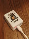
ESP32-CAM AI-Thinker CASING
NEW VERSION: https://makerworld.com/en/models/246973 & https://makerworld.com/en/models/246514
Ball joint / Ball screw / Ball base Credit: DieZopfe - https://www.thingiverse.com/thing:4739696
- ESP32Cam-Case2vents+usb+mb-space.stl (Case with space for esp32-cam-mb, usb plug and tiny air gap at the top)
- ESP32Cam-Case2vents+topseal.stl (Case without antenna hole, ideal for outdoor)
- ESP32Cam-Caseantennahole+2vents+topseal.stl (Case with antenna hole, ideal for outdoor)
- ESP32Cam-Caseantennahole+3vents.stl (Case with antennahole, and 3 vents at bottom and tiny air gap at the top)
Before i started work on this case, i wanted it to have the following features:
- Movable mount, considered gopro style, but ended up with ball joint (which works perfect for my usecase)
- Changable lens holder (stock 8x8mm lens, aswell as bigger 14x14mm lenses in the future)
- Easy to print with no supports (my printer sucks)
- Very little hardware required
- USB or pin powered, with ability to leave ESP32-CAM-MB attached inside
- SD-card space
Hardware required:
- 4x m2.5x4 (Lens adaptor)
- 4x m2.5x5 (Front-casing mount to rear-casing)
- 2x m2x5 (Rear-casing to ball-joint)
- 1x m2x6 (Mounting-extension - 6mm screw or longer)
Assembly:
- Check clearances (14x14 lens with screw tabs doesnt fit unless the tabs are removed)
- Screw lens plate to front casing with 4x m2.5x4 screws
- Insert ESP32-Cam with camera (and antenna cable if used) - Mind the cable and be gentle.
- Push antenna screw through top-hole (if used)
- Screw ball-joint WITH finger-screw in between to the rear casing with 2x M2x5 screws
- Run cables through rear casing, and connect to esp board (5v top right, GND right below, AI-thinker board)
- Push rear casing into front casing (Mind then antenna cable - i found that if you push antenna cable through the bottom vent, its easier to manage)
- Last 4 screws goes in both sides, top and bottom.
Et voilà
License
This user content is licensed under a
Creative Commons Attribution-Noncommercial-Share Alike
Comment & Rating (26)