Canyon Jump Bike Model


Print Profile(4)


Description
Boost Me (for free)
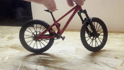
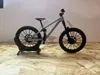
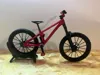
Canyon Stitched 720 Model Bike1:9 Scale:
This is a 1.9 scale Jump bike model based off a Canyon Stitched 720 with rotating wheels, crank and pedals with pivoting frame and with spring loaded front and rear suspension.
Feedback greatly appreciated!
Pre-assembly:
Some parts may need sanding/filing before assembly to ensure a perfect fit.
**(Make sure to clear all supports from around pivoting joints of frame and rear shock before attempting to free off pivoting joints)**
Tools needed:
- Drill bit. (2mm, 4mm, 5mm & 6mm)
- Glue.
- Rasp/small file or sandpaper.
- Springs:
Fork spring: (Outer diameter 4mm, length 30-40mm)
Rear shock spring: (Outer diameter 4-5mm, length 15mm)
**(Drill bits to be used only by hand or pliers to prevent damage to parts)**
2mm drill bit used for pedals and rear suspension, 4mm drill bit used for wheel hubs (if needed), 5mm drill bit used for Headset hole on the frame, 6mm drill bit used for bottom bracket/rear frame.
Assembly guide:
Step 1 (Wheel assembly):
Place the alignment blocks (2 white pieces) into the correct cut outs on one half of the wheel.
Apply glue all round and then place the second half of the wheel onto the first. (don't forget to align the tread pattern of the wheels)
(As shown below)


(Repeat step one for other wheel)
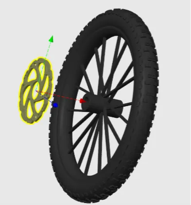
Step 2 (Rotor assembly):
Slide Rotor onto the left side of the rear hub.
(As shown below)

Step 3 (Fork assembly):
3.1: Slide the fork stanchions into the fork lower body from the bottom.
(As shown below)

3.2: Next slide in the spring. (outer diameter 4mm, length 30-40mm)
(As shown below)

3.3: Then push in the caps at the bottom. (glue in place if needed)
(As shown below)

- 3.4
Next push the stanchions into the Fork Crown. (As shown below)


- 3.5
Slide the Front Wheel into the fork lower then secure with Front Axle. (As shown below)


- STEP 4
Cockpit Assembly
Slide the Stem through the Handlebar till it’s in the center.


- 4.2
Next slide on Brakes and Grips.

- Step 5
Seat Assembly
Glue the two halves of the Seat together.
- Step 6
Main Assembly
Step 6: (Crank, Crank arm and Pedal assembly)
(Use 6mm drill bit by hand or pliers if needed to clear the holes on the frame and subframe)
6.1: Slide the crank through the chain, frame and subframe ensuring all pieces are attached and secured in place on the other side with the crank cap.
(As shown below)

6.2: Grab the crank arms and attach them on both sides of the crank via the square holes.
(As shown below)

(Use a 2mm drill bit by hand to open holes on pedals and use rasp/file or sandpaper to file down any support material on pedal pins of crank arms to ensure pedals move freely)
6.3: Slide pedals onto pedal pins. (Apply small amount of heat to end of pedal pins and flatten slightly to ensure pedals do not slide off pins. Be sure not to over-press the end of the pedal pins to prevent pedals sticking to pins/melting together)
(As shown below)


Step 7: (Rear Shock assembly)
(Use 2mm drill bit to clear rear shock hole and use rasp/file or sandpaper to remove any existing support on rear shock link)
Place the rear shock spring: (Outer diameter 4-5mm, length 15mm) onto the rear shock and secure in place with rear shock link.
(As shown below)

Step 8: (Rear Wheel to Frame assembly)
(Use 4mm drill bit if needed to clear hubs on wheel)
Centre rear wheel and gear/chain with rear of frame and secure in place with rear axle.
(As shown below)

- 9.1
Get the Fork Assembly you made earlier and push it through the Headtube of the Frame then place the spacer on top.

- 9.2
Finally push on the Stem and apply a little glue.

Enjoy.

License
You shall not share, sub-license, sell, rent, host, transfer, or distribute in any way the digital or 3D printed versions of this object, nor any other derivative work of this object in its digital or physical format (including - but not limited to - remixes of this object, and hosting on other digital platforms). The objects may not be used without permission in any way whatsoever in which you charge money, or collect fees.
Comment & Rating (29)