
Wireless Laser Engraver -- Wujie Plus
Print Profile(1)

Description
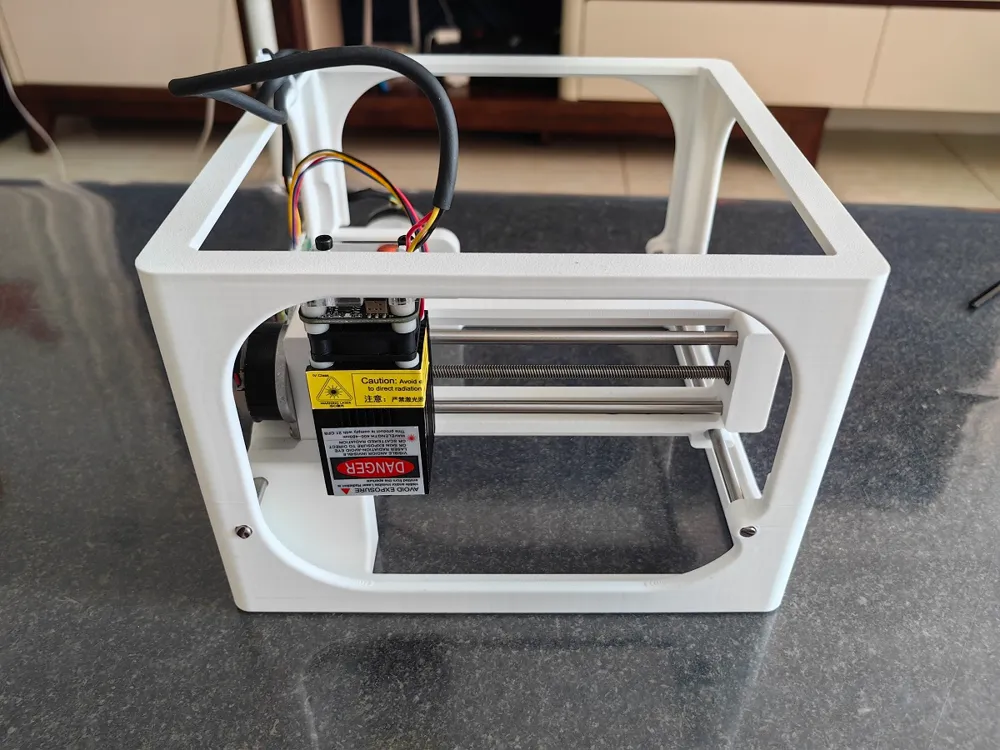
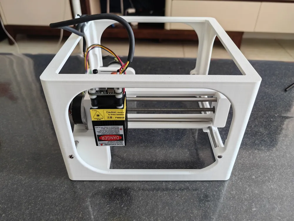
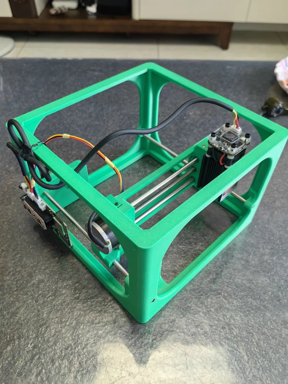
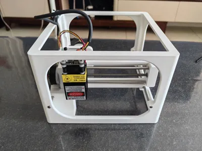
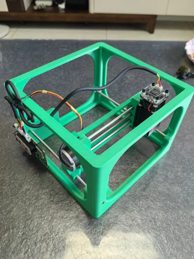
Open-source Wireless Laser Engraver - Wujie PLUS, the Wujie Plus wireless laser engraver extends the effective travel of my previously open-sourced Wujie No. 2 and is equipped with a 2.5W laser head, giving it certain tool properties. The complete set of data is also open-sourced on the Jiali Chuang Hardware Open-Source Platform, with the open-source link: Wireless Laser Engraver—Wujie PLUS - LICHUANG Open-Source Hardware Platform
The complete set of data includes circuit boards, 3D printing models, configuration files, etc., as well as sharing related software and program firmware.
1. Project Introduction:
This project is designed based on the GITHUB open-source project Fluid NC. The open-source content includes the implementation scheme, circuit board, and mechanical structure of the engraver designed by me. I have shared the complete development process on Douyin and Bilibili, with the usernames: Liuruifeng. If you are interested, please give me a like, favorite, and follow, I would be very grateful.
- Function Description:
Since the 2.5W laser head was replaced, the laser engraver's power requirements are: 12V, 2.5A. It communicates with mobile phones or computers via Bluetooth or WIFI, freeing it from the constraints of wired connections. The engraving range is 120mm*110mm. The PC software used is the open-source software LaserGrbl, and the mobile software is MKSlaser. MKSlaser requires engraving files to be uploaded to the engraver's memory card before engraving. When using the memory card, it must be in WIFI mode; Bluetooth mode does not support transferring files to the memory card.
3. Main Hardware Analysis
1) The project's main controller is developed using the ESP32 microcontroller. Compatible chips can be used, costing around 9 yuan. It supports three connection methods: serial port, WIFI, and Bluetooth. Limited by ESP32 chip resources, only one of Bluetooth or WIFI can be supported simultaneously, but the serial port can be used simultaneously with Bluetooth or WIFI.
Special note: The 3.3V power required by the ESP32 chip is stepped down from a 12V power supply. If you need to use the serial port to write firmware or configuration files, it must be done with both the 12V power supply and the TYPE-C interface connected simultaneously. Connecting only the TYPE-C data cable will not allow writing firmware or configuration files via the serial port.
2) The stepper motor uses a 36-disc stepper motor. The cost of a disassembled motor is 5-8 yuan (usually not including shipping). It has a step angle of 0.9 degrees, an output shaft diameter of 5mm, and a length of 8.5mm.
3) Motor lead screw: T5 lead screw, 5mm diameter, 150mm length, 4mm lead (the lead screw travels 4mm per revolution), costing about 14 yuan. The Wujie PLUS changed the lead screw's lead to 4mm, making it run smoother and quieter while maintaining accuracy.
4) Four optical axes with a diameter of 5mm are used: two for the X-axis (160mm long) and two for the Y-axis (200mm long). The 160mm optical axes need to be custom cut.
5) The motor driver uses A4988, costing about 3.5 yuan each, and two are needed. The driver uses a 16-microstep mode. One rotation of the motor requires 360/0.9=400 pulses. Theoretically, it can achieve 400/4*16=1600 pulses per 1mm of travel. The engraving accuracy will not be further demonstrated here; you can test it after assembly during replication. It should meet the requirements for general engraving tasks.
6) The circuit board is compatible with 5V, 250mW, and 12V 2.5W laser heads. The 250mW laser head uses an XH2.54-2P connector, while the 2.5W laser head uses an XH2.54-3P connector. The 2.5W laser head uses PWM dimming. It does not support using two types of laser heads simultaneously; switching laser heads requires switching different configuration files. Note that the circuit board is not compatible with Wujie No. 1/No. 2, and the overall layout has been adjusted.
7) 2.5W laser head: 12V power input, 3-wire with PWM/TTL control, has a weak light mode button to enable weak light for focusing. The weak light switch needs to be turned off during engraving. Laser head dimensions: 33*33*78. The main reason for choosing this laser head is its small size, so the engraver does not need to be designed very large. The same laser head is available on Taobao from Sanwu Electronics and Xinrui Technology (PS. No cooperative relationship, I purchased it from here for reference only; if you have a cheaper source, please provide it).
8) Memory card: Fluid NC firmware explicitly states that 2GB memory cards are unusable, while 16GB memory cards have been verified to work. It is recommended to buy a large-brand memory card. I bought an 8GB one cheaply, which could not be recognized. I am unsure if it's due to firmware incompatibility or an issue with the memory card itself.
4. Material Description:
The required mechanical and electrical components are listed in the attached BOM table. This BOM table was manually typed, so there may be discrepancies in quantities or models. If there are any discrepancies, please check the schematic diagram. Your understanding is appreciated.
5. Precautions
1) Silkscreen on the A4988 driver board for motor connection: 1A, 1B are one phase winding, and 2A, 2B are another phase winding. Stepper motors are generally marked with A+, A- as one phase winding and B+, B- as another phase winding. Special attention should be paid when connecting the circuit board and the motor.
I have marked the silkscreen of the motor and circuit board, and the motor wire colors on the circuit board. The wire colors match the motor I purchased. When replicating it yourself, the motor wire colors you buy may be different from mine. Even if the colors are the same, the motor windings may not correspond to the wire colors. You need to distinguish the motor winding phase sequence yourself. If there is a problem with the motor's rotation direction, you can adjust the wire sequence of the motor extension cable to match the circuit board's silkscreen wiring.
2) The coupling between the motor and the lead screw is 3D Printed. During installation, the large end face of the coupling should be flush with the motor and pressed down completely. The lead screw should also be pressed into alignment with the motor output shaft to ensure concentricity between the motor and the lead screw when rotating. The coupling has reserved set screw mounting holes, using 2.5*2mm set screws, and you can choose whether to install them.
License

You shall not share, sub-license, sell, rent, host, transfer, or distribute in any way the digital or 3D printed versions of this object, nor any other derivative work of this object in its digital or physical format (including - but not limited to - remixes of this object, and hosting on other digital platforms). The objects may not be used without permission in any way whatsoever in which you charge money, or collect fees.


Comment & Rating (0)