
Xbox Series XS Controller ABXY Clicky Mod
Print Profile(1)

Description
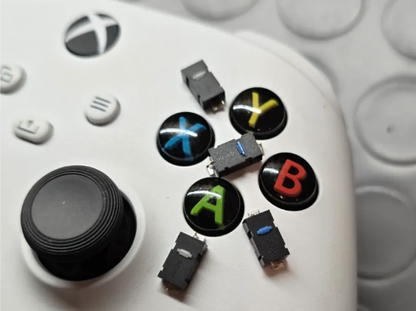
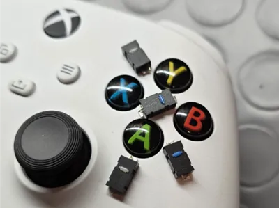
This modification replaces the conductive rubber pads (membrane) of the ABXY buttons with tactile microswitches (clicky), ensuring faster and more precise feedback ("mouse click" type)
Below is the Guide to make it, let me know if you have any tips for improving it and remember to show me photos of your modified controller, have fun!
Difficulty Level and Requirements
- Difficulty: Medium-High (requires micro-soldering, handling SMD components, and 3D printing), in this guide I assume you know how to disassemble an Xbox controller
- Risk: High risk of damaging the PCB, internal shell, and buttons. The mod is reversible by replacing the modified buttons
- Cost: Having the tools and the ability to print available, costs are relatively low; microswitches are easy to find and have a negligible price compared to a ready-made clicky kit
Materials Needed
| Component | Recommended Specifications | Project Notes |
|---|---|---|
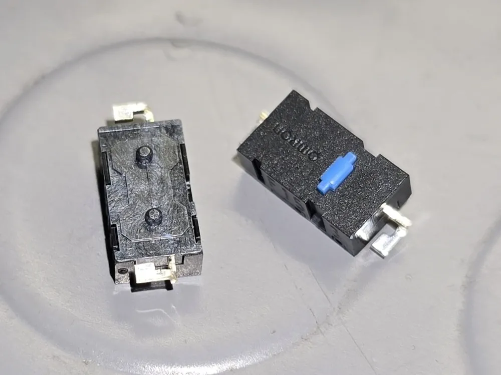
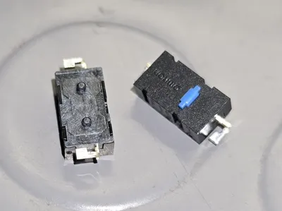
| Tactile Microswitches (4 pcs) | Omron D2LS-21 (0.6N) or D2LS-11 (1.2 N) | Offer excellent tactile feedback |
| Wiring Cable | Enamelled Copper (Magnet Wire) | AWG 30 |
| Adhesives/Fixing | Kapton tape, thin and strong double-sided tape, Epoxy/UV Resin | Double-sided tape for reversible mounting of supports, resin for switch locking |
| Tools | Fine-tip soldering iron, Flux, Isopropyl Alcohol, 600 grit sandpaper, wire cutters, multimeter |
Disassembly:
Desolder the rumble motor wires and remove the two main PCBs: the Button Board (which houses A, X, Y) and the MCU Board (which houses B)
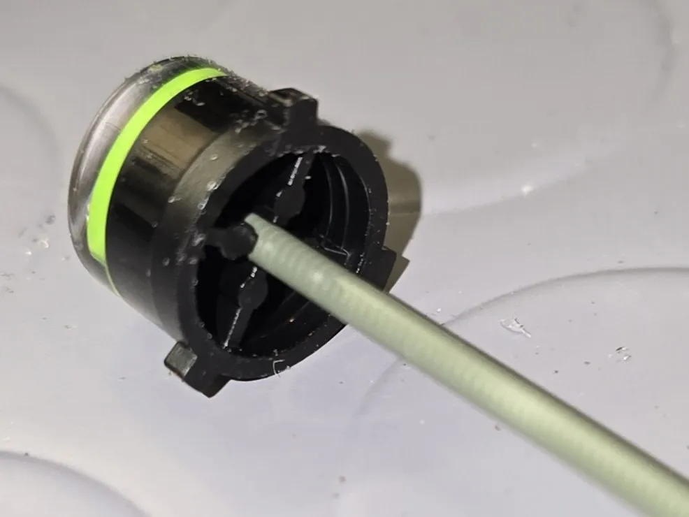
Modifying the Original Buttons:
To compensate for the additional height of the SMD switches (compared to rubber membranes) and to allow:
- Filling: The original external buttons are hollow. Fill the internal void by inserting and cutting a piece of 3D printing filament (1.75 mm)
- Calibration: Remove approximately 1 mm of material from the bottom of this filling (using 600 grit sandpaper) to calibrate the height. This allows the button to rest correctly on the switch actuator
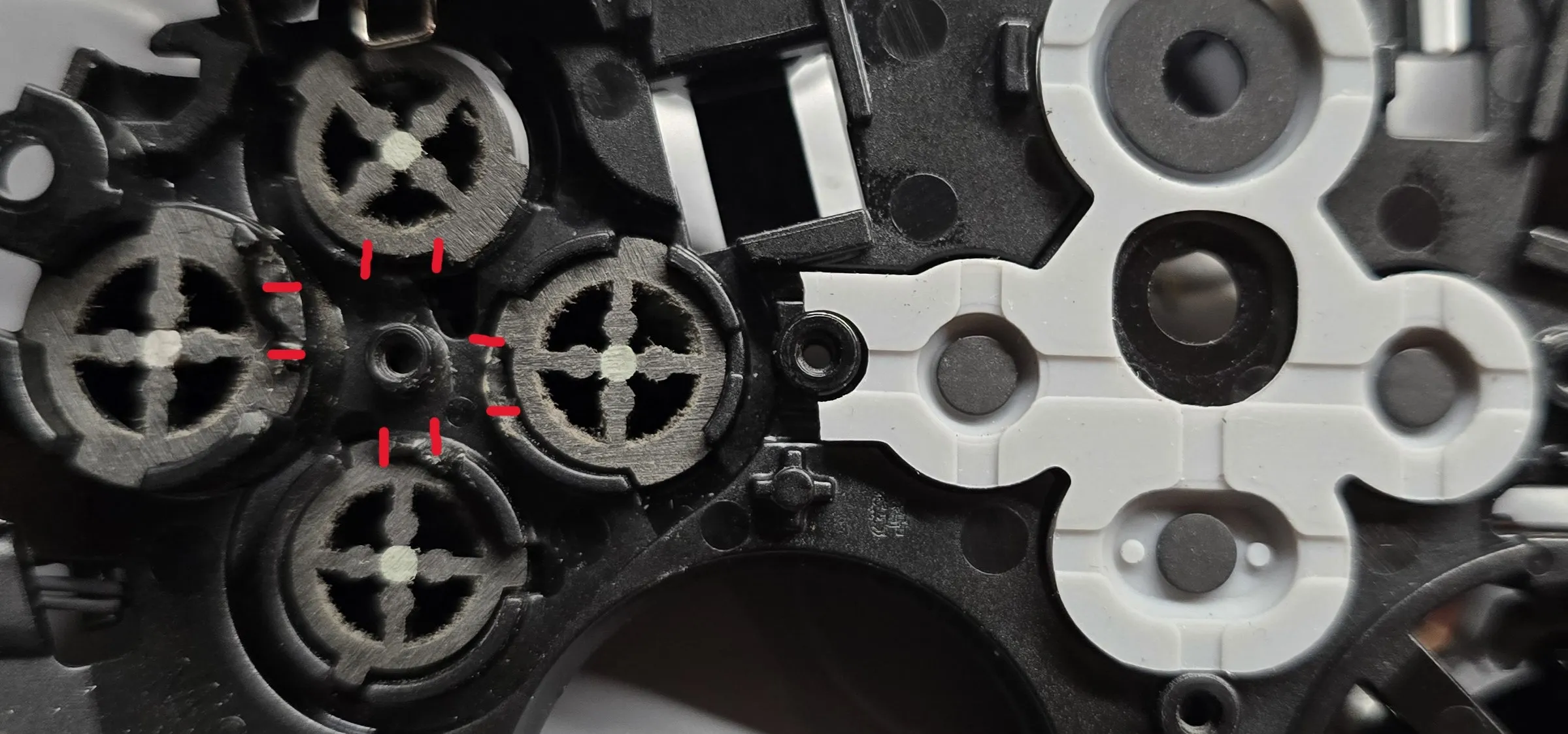
- Shell Modification: It will be necessary to create the space needed to insert the microswitches, file or cut with wire cutters the points of the shell indicated in red in the image
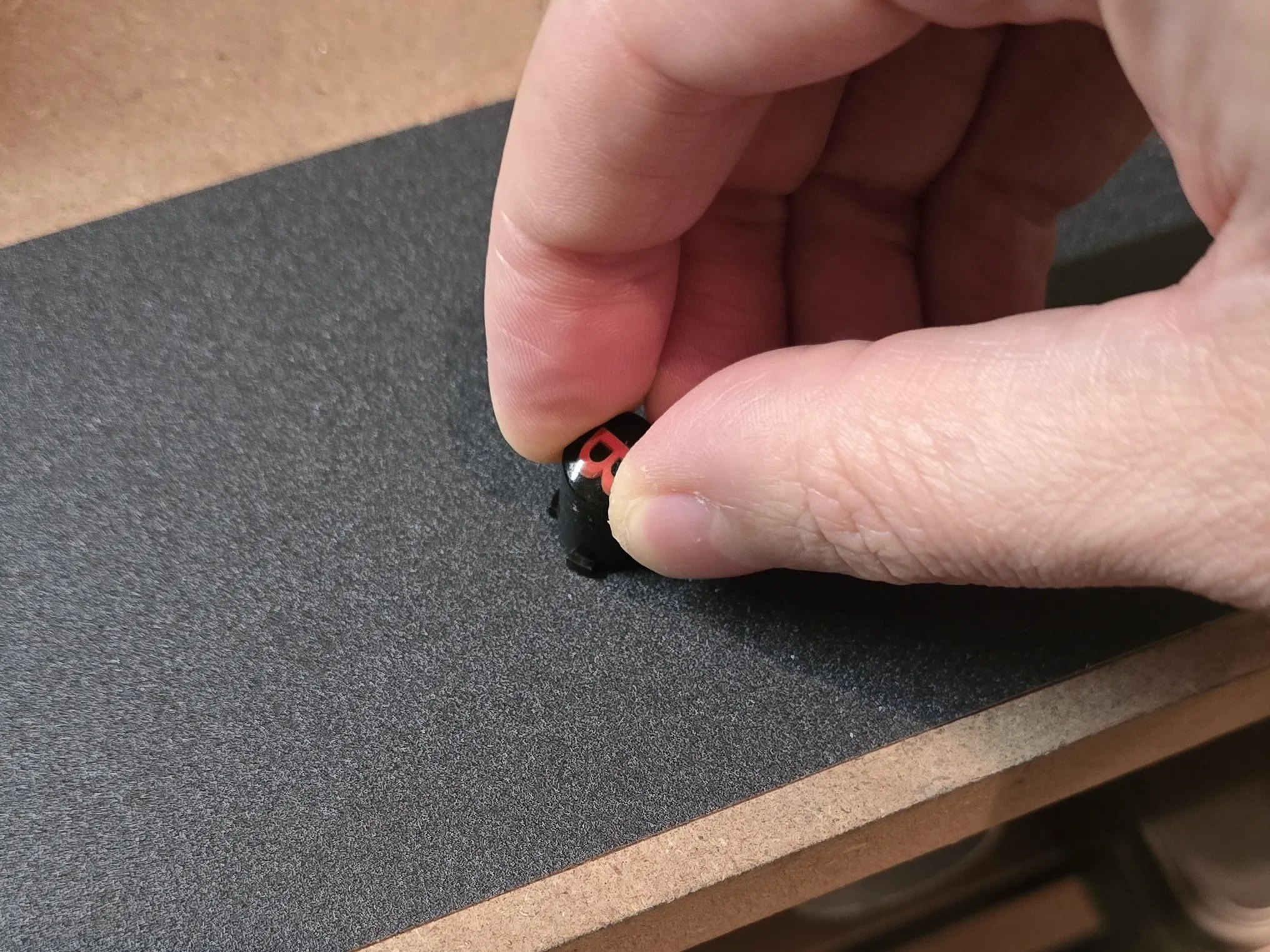
Provisional mounting: Insert the modified external button into the shell, then the corresponding button support, including the switch, mount the PCB by screwing in only the adjacent screws
Test: If the button is already pressed or does not press correctly, remove more material from the base of the external button and repeat step 3.
If you have removed too much material from the button, add it using resin or thin layers of plastic and repeat step 3Cut the button membrane in half (as in the photo below)
Soldering the Microswitches:
Apply a small amount of flux to each microswitch terminal and pre-tin them
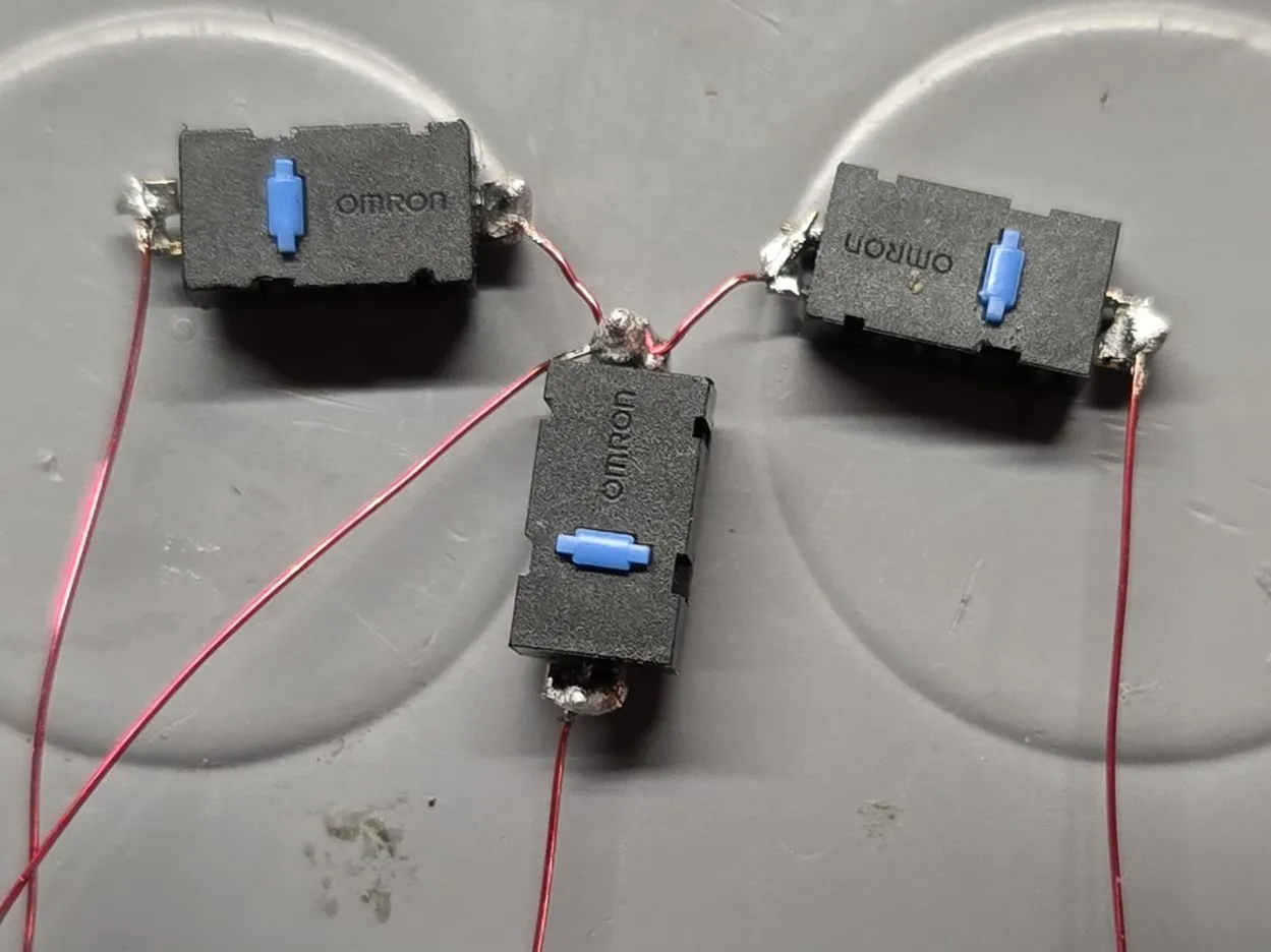
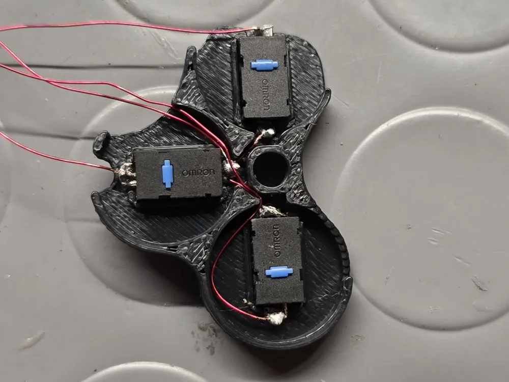
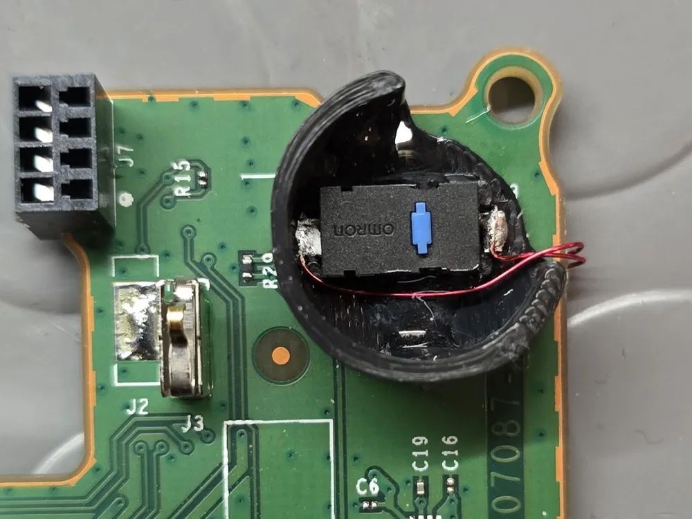
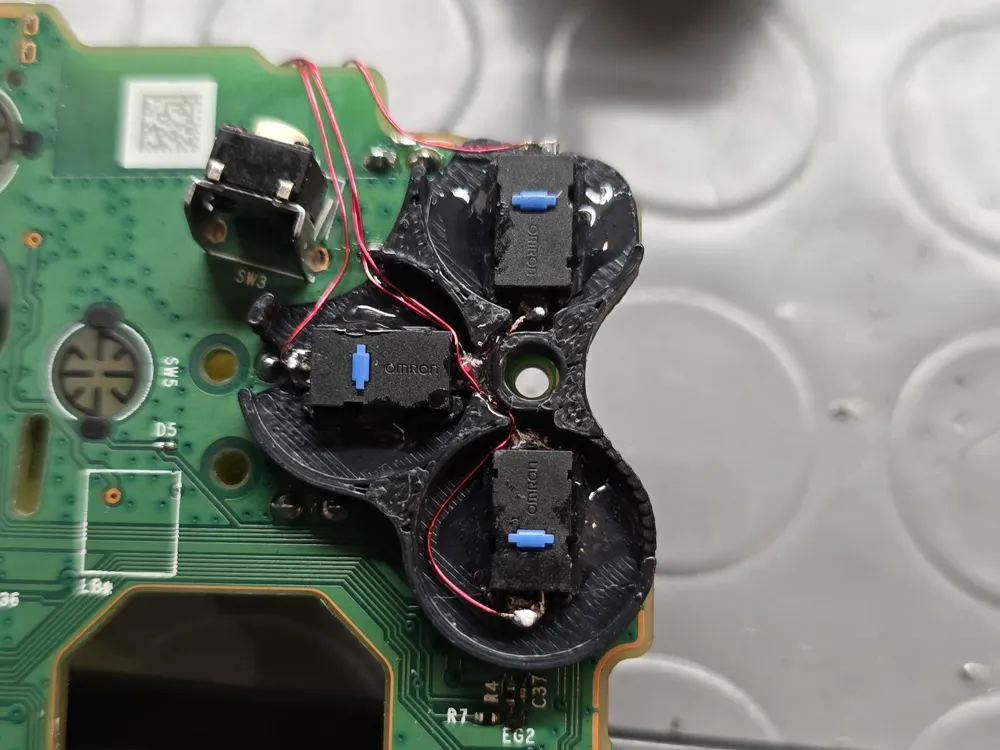
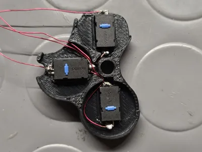
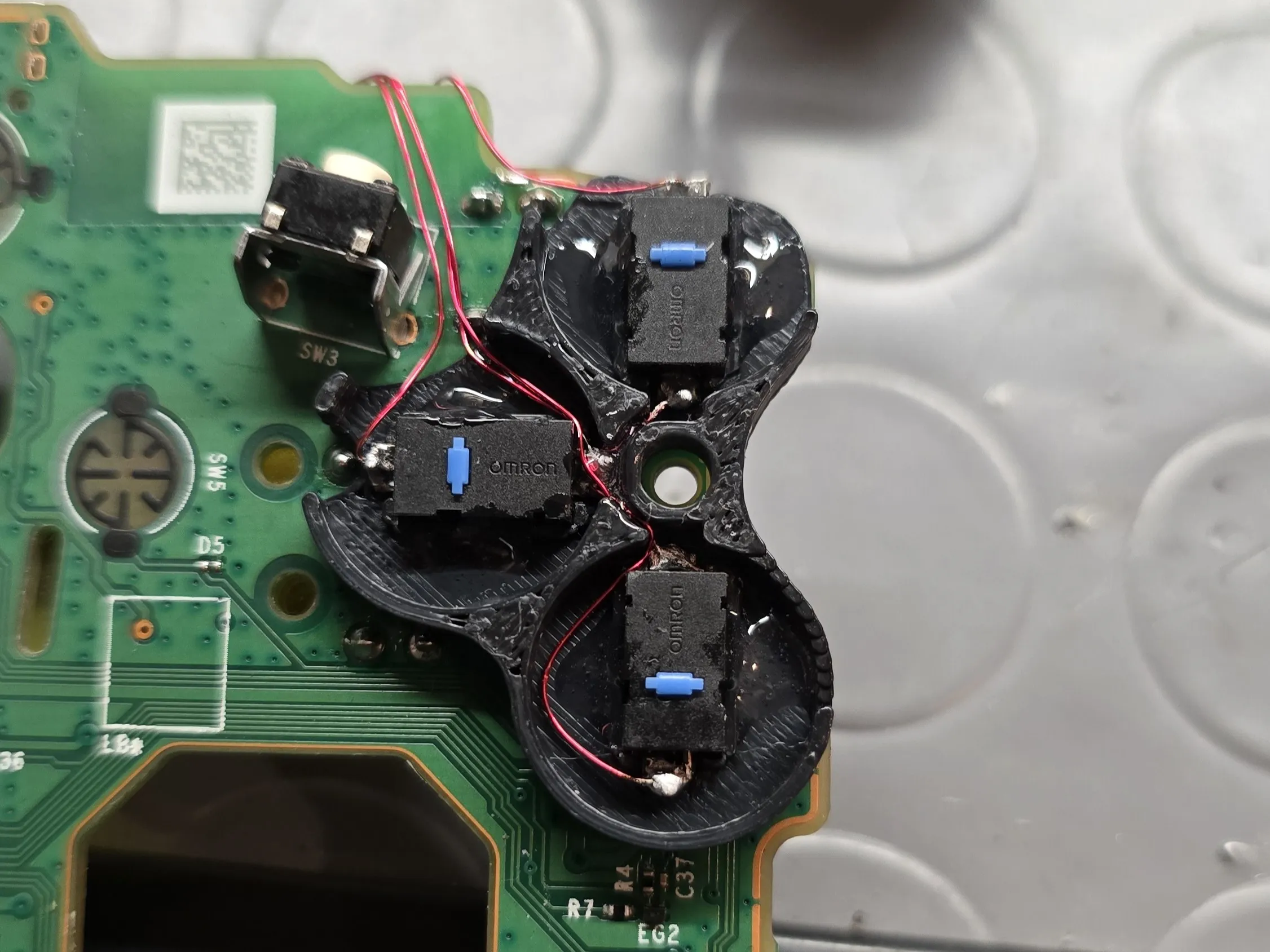
- Solder 3 switches together, using the enamelled copper wire, making sure they are oriented with the actuator facing outwards, as in the photo, so that they are directly under the button. You can use a single wire and leave 8-10 centimeters of excess
- To the other terminal of the 3 switches, solder 3 pieces of wire approximately 10 cm long
- Switch Installation: Insert the SMD microswitches into the slots; they should snap into place
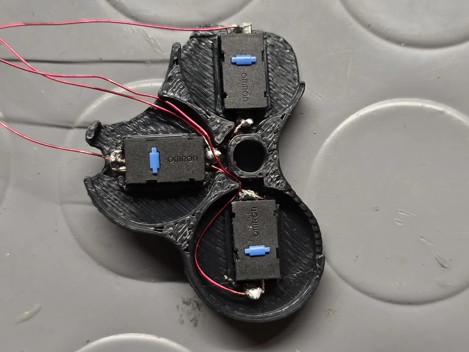
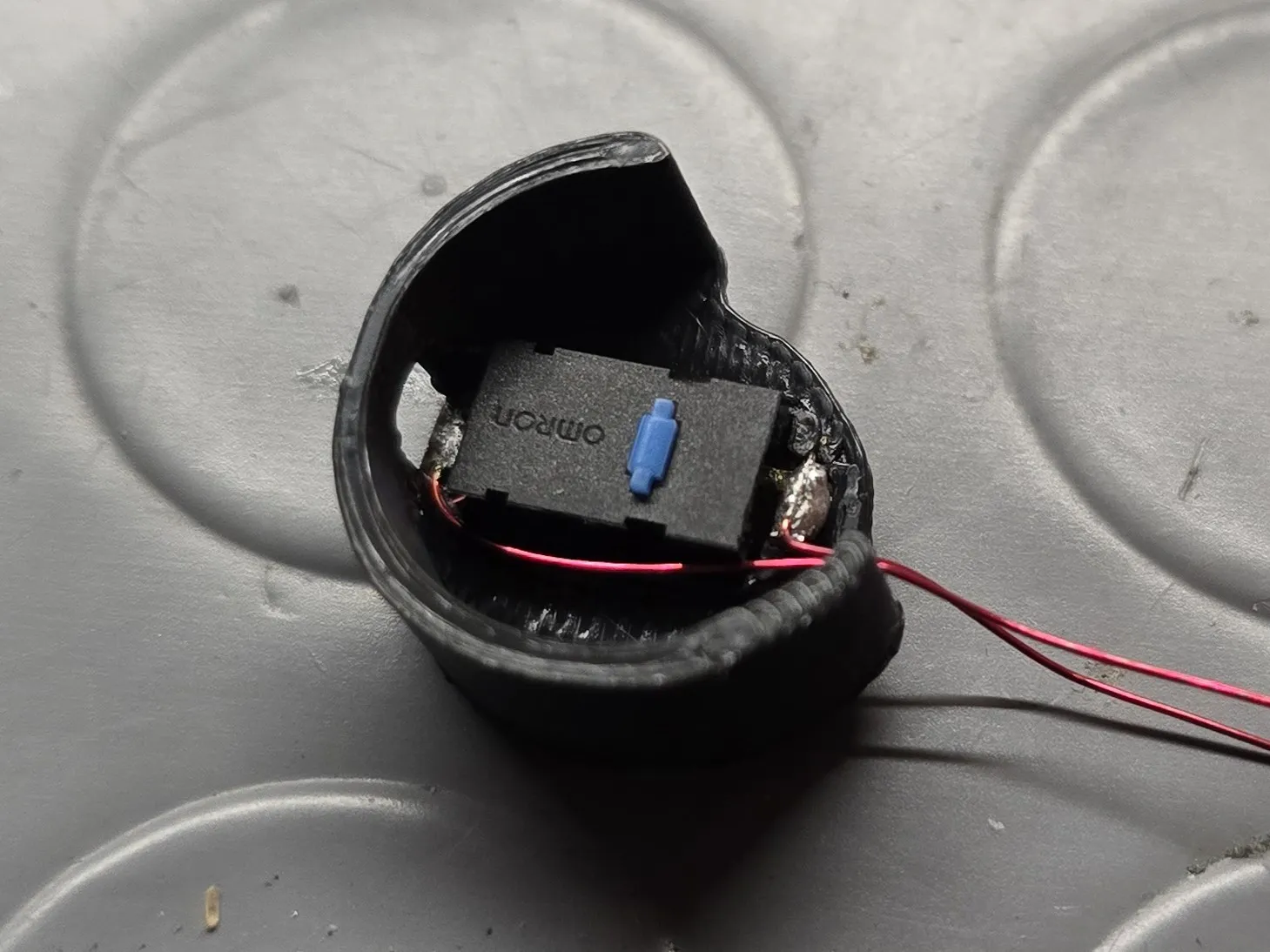
Securing Supports:
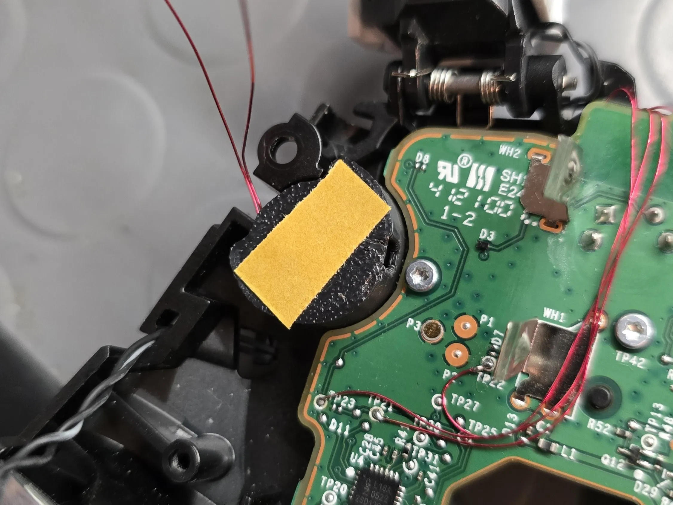
- Cleaning: Clean the ABXY pad area on both boards with isopropyl alcohol
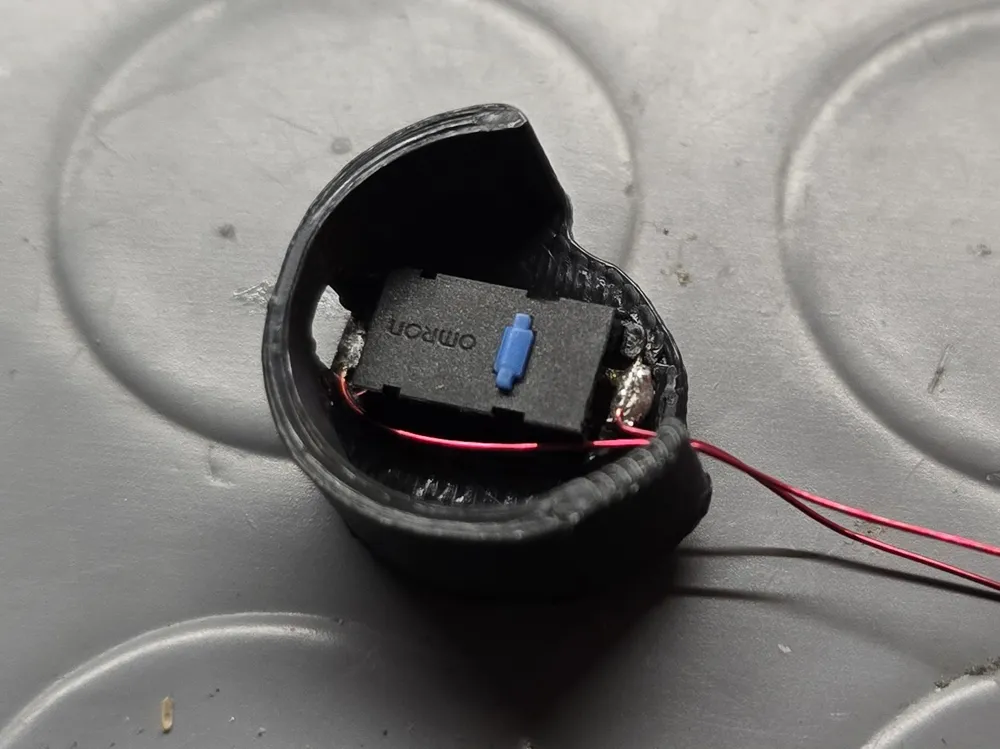
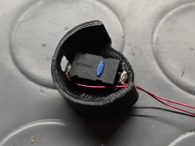
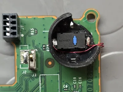
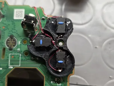
- 3D Printed Supports: It is recommended to insert the supports onto the shell, apply thin double-sided tape (to maintain reversibility) to the base, and then press the PCBs firmly onto them
- Large Support (A, X, Y): Secure it to the Button Board
- Small Support (B): Secure it to the MCU Board
- Position the cables so they are not damaged by the shell (see photo)
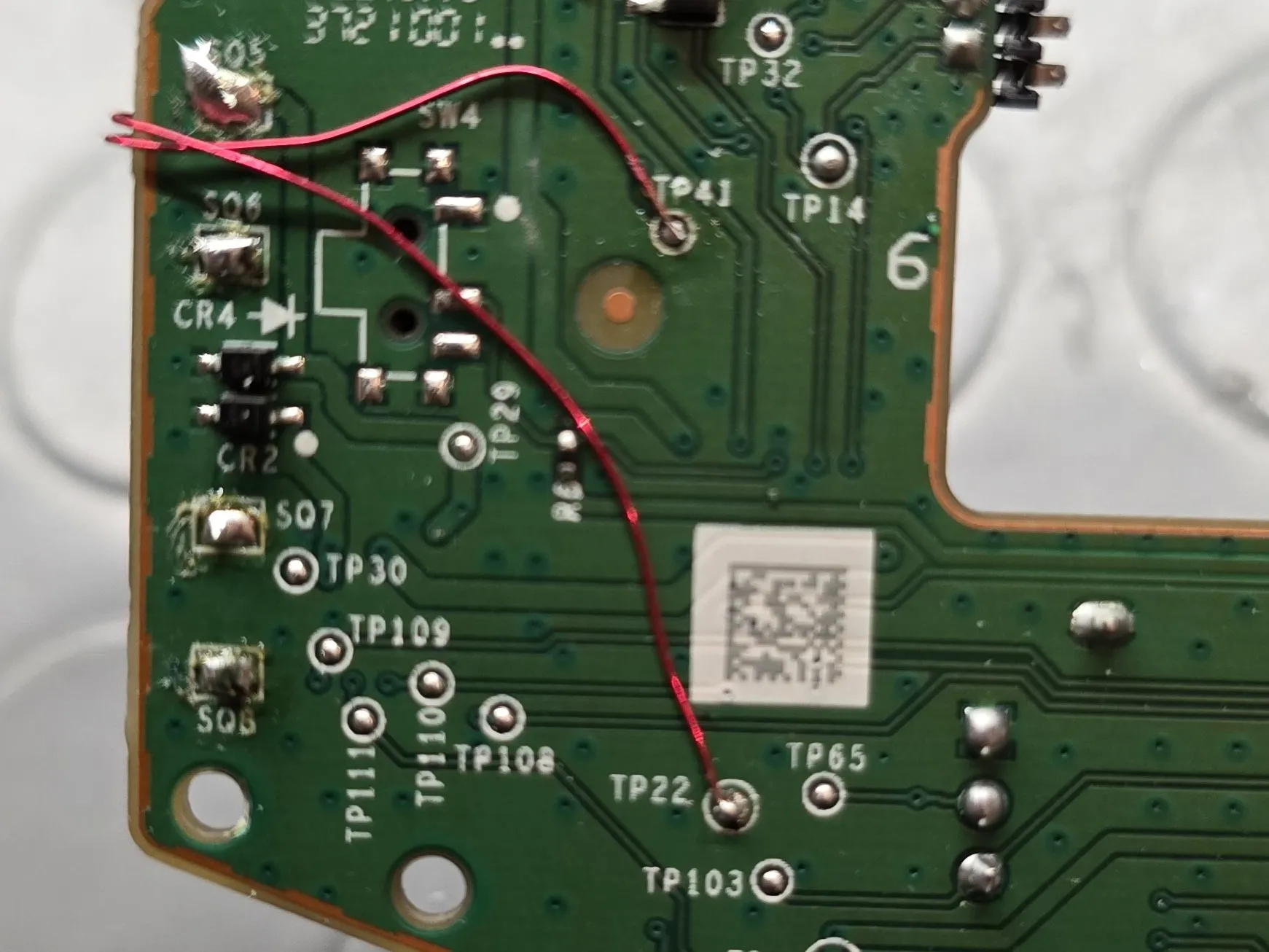
Soldering the Test Points:
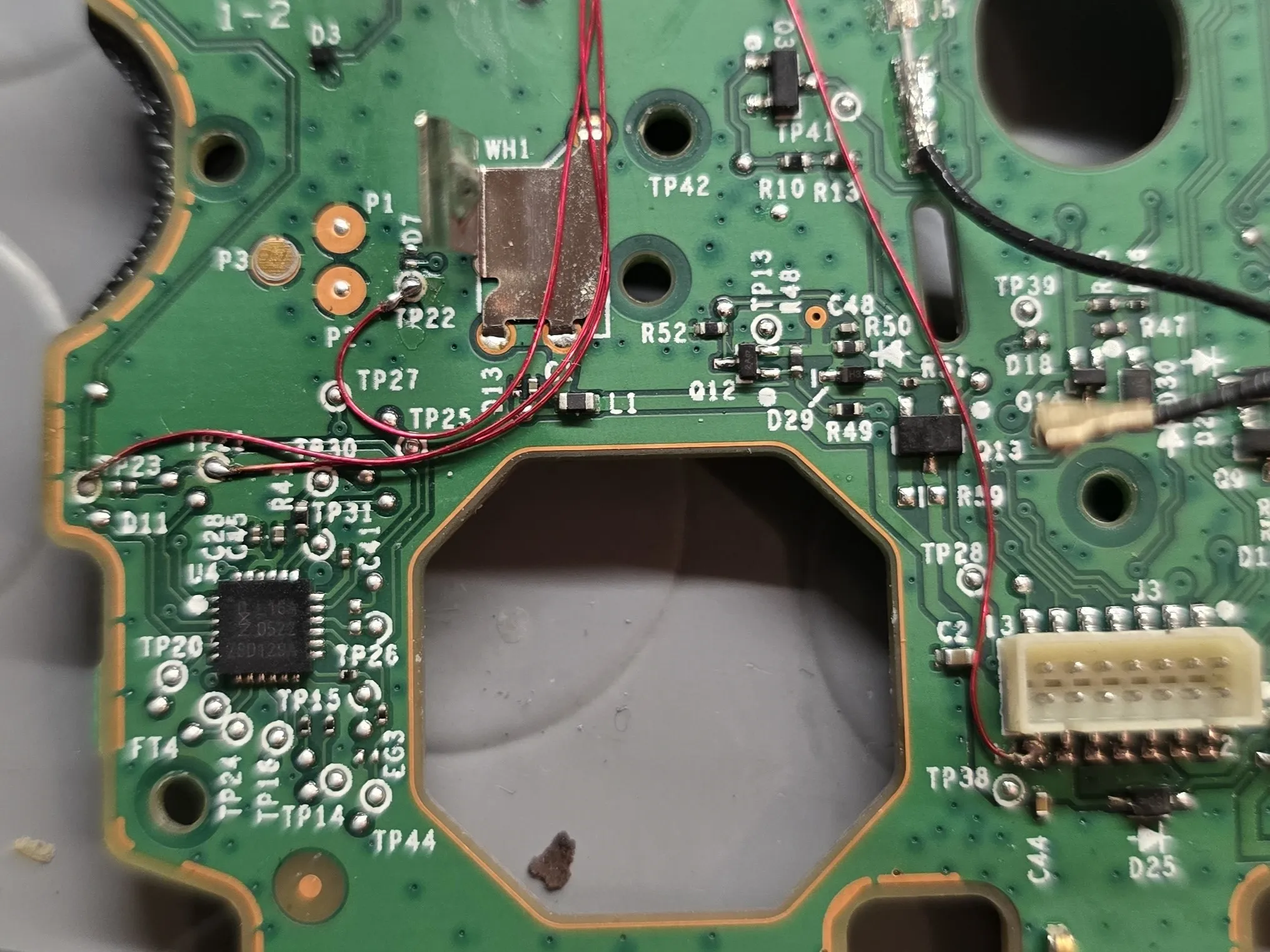
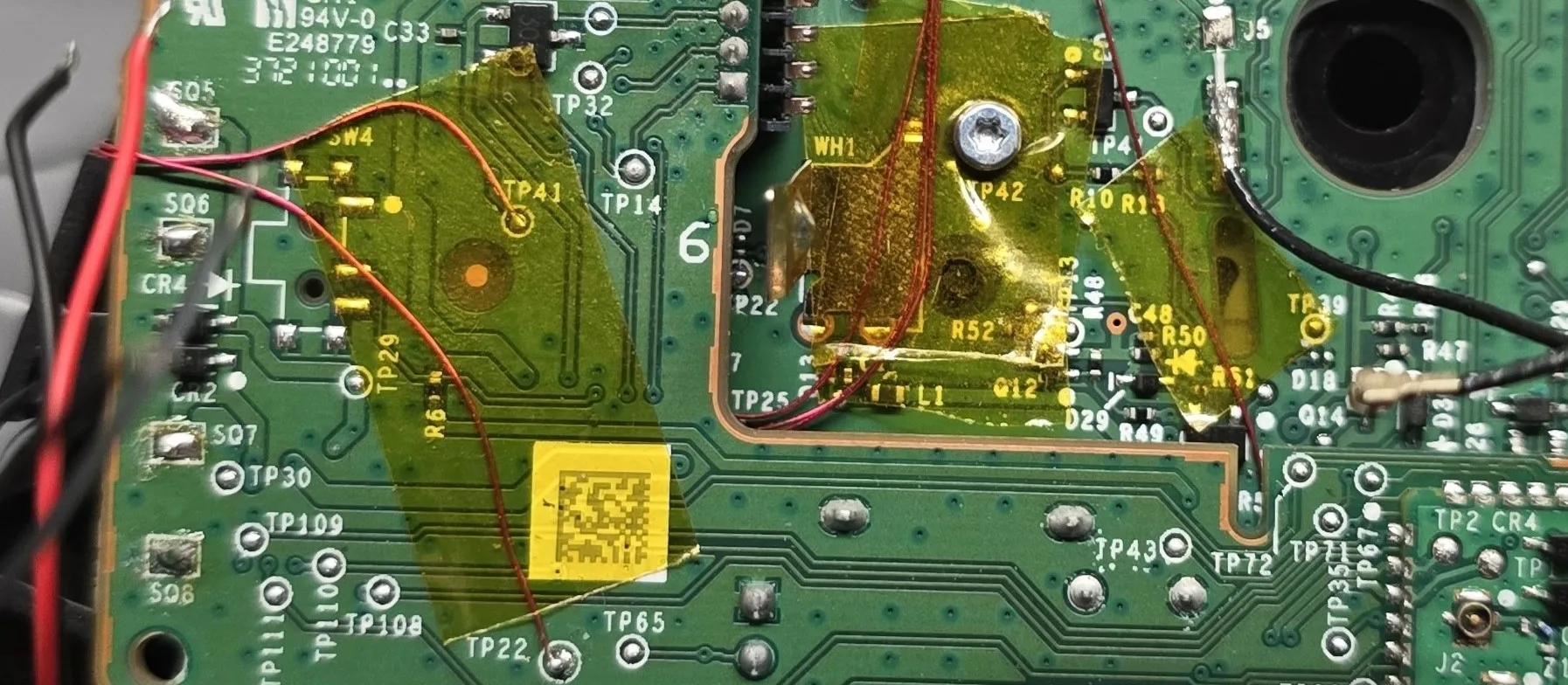
Soldering must be performed on the exposed Test Points to intercept the signal. Remember: the 3 GNDs of switches A, X, and Y must be connected together to a single GND point on the PCB.
Button Board (A, X, Y Buttons)
Button | Function | Test Point (TP) to Solder |
|---|---|---|
A | Signal | TP21 |
X | Signal | TP22 |
Y | Signal | TP23 |
GND | Common Ground | Any GND pin |
MCU Board (B Button)
Button | Function | Test Point (TP) to Solder |
|---|---|---|
B | Signal | TP41 |
GND | Common Ground | Any GND pin |
Note on GND: It is recommended to use Pin 14 (Button Board) and TP22 (MCU Board) as GND points. The common (single) cable connecting the GND pins of the 3 switches should be connected to pin 14; the other point is GND only for B. This serves to keep the wiring separate from the two PCBs, facilitating their disassembly
Functionality Test:
Now you can check the solders and microswitch functionality with a multimeter. Alternatively, mount the PCBs, leaving the rumble motors disconnected, and test the controller via USB on any compatible device
If the functionality is not correct, proceed with disassembly and recheck the non-working buttons with a multimeter
Final Assembly
- Disassemble the controller's two PCBs one last time
- Apply a drop of epoxy resin in a non-critical spot (sides) to permanently secure the switches in their supports
- Secure the enamelled wires with Kapton tape so they cannot move
Mount the boards, solder the rumble motor wires, and close the controller
License

You shall not share, sub-license, sell, rent, host, transfer, or distribute in any way the digital or 3D printed versions of this object, nor any other derivative work of this object in its digital or physical format (including - but not limited to - remixes of this object, and hosting on other digital platforms). The objects may not be used without permission in any way whatsoever in which you charge money, or collect fees.


Comment & Rating (0)