

Print Profile(1)

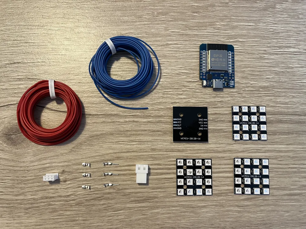
Bill of Materials



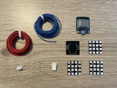
- ESP32 D1 Mini (USB-C) x 1: https://aliexpress.com/item/1005007649269367.html
- 30x30 mm, 4x4 LED Matrix (WS2812B) x 4: https://aliexpress.com/item/1005010216139423.html
- JST-XH 2,5 mm 3P Plug Housing x 1:
- JST-XH 2,5 mm Female Terminal x 3:
- JST-XH 2,5 mm 3P Receptable Housing x 1:
- JST-XH 2,5 mm Male Terminal x 3:
- 5 cm wire x 12:
- 13 cm wire x 3:
Description
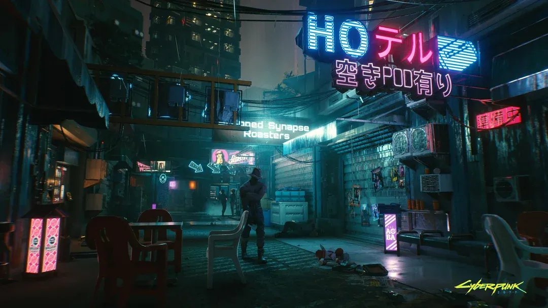
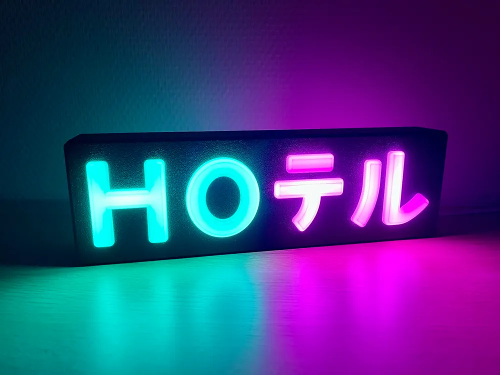
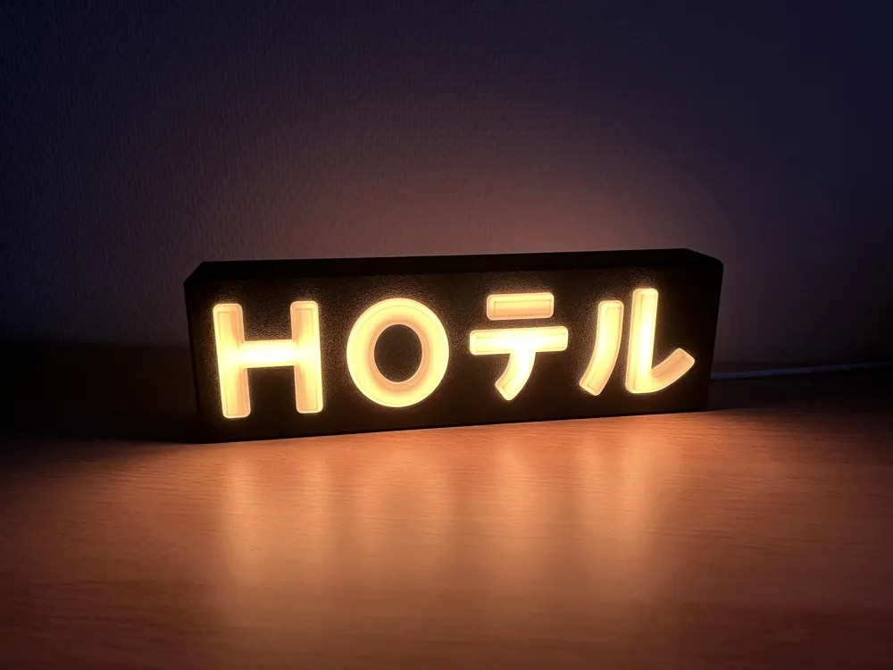
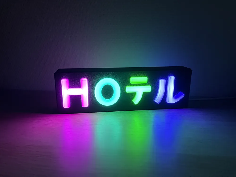
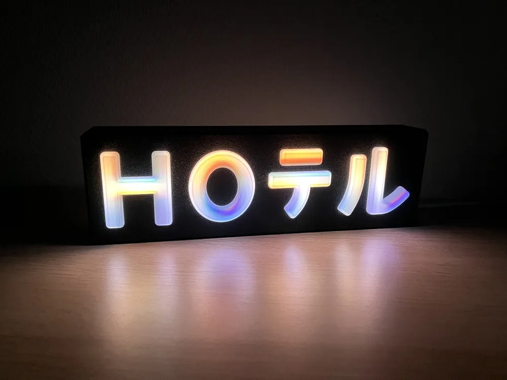
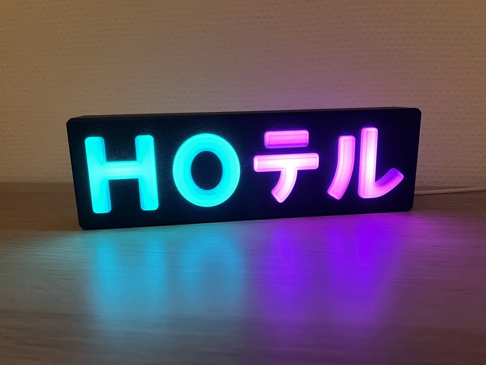
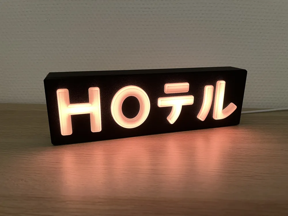
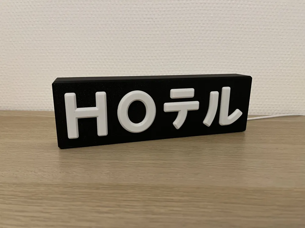
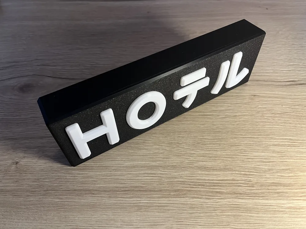
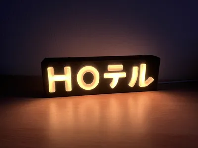
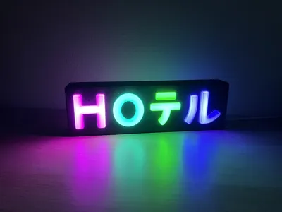
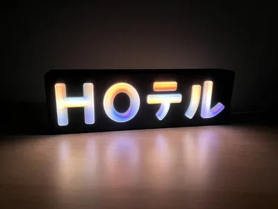
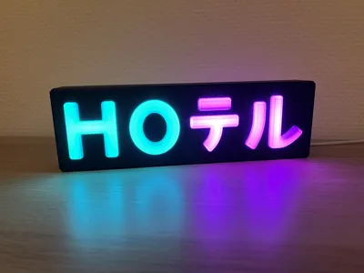
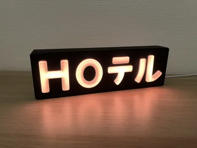
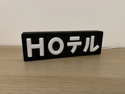
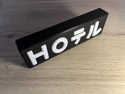
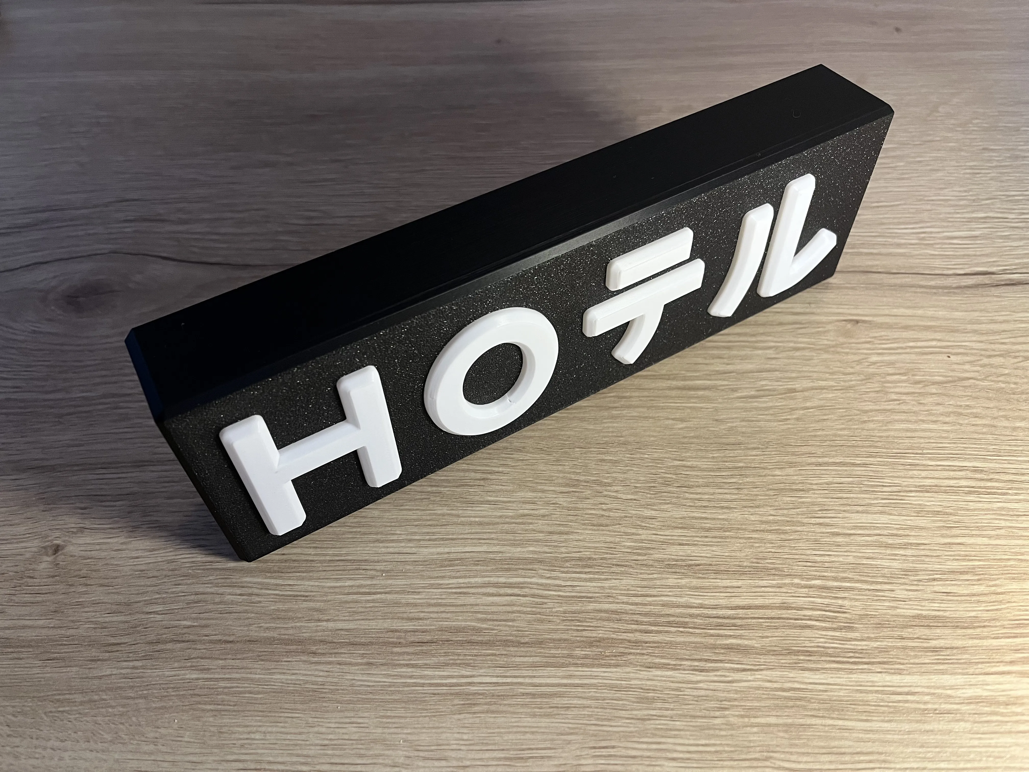
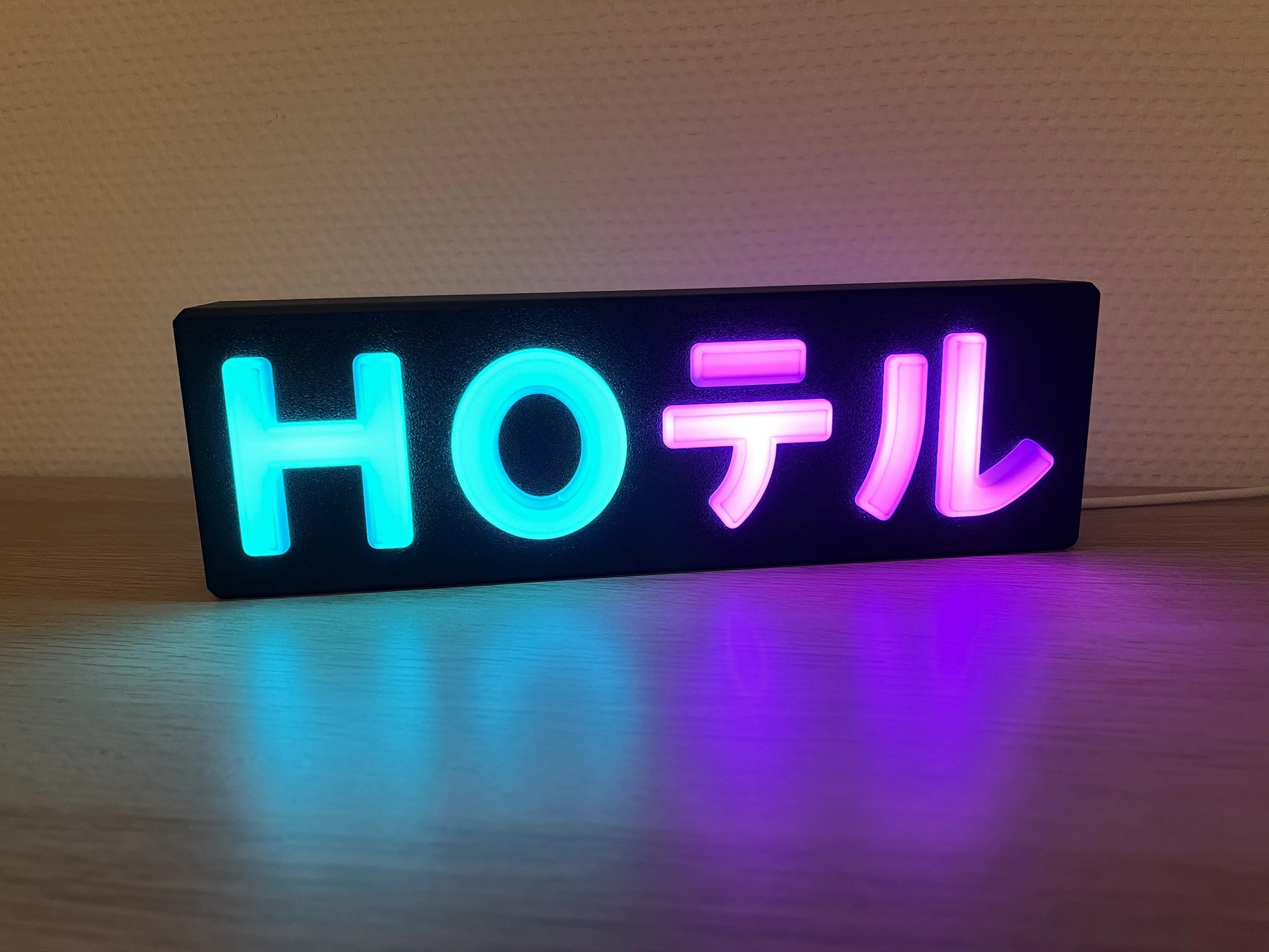
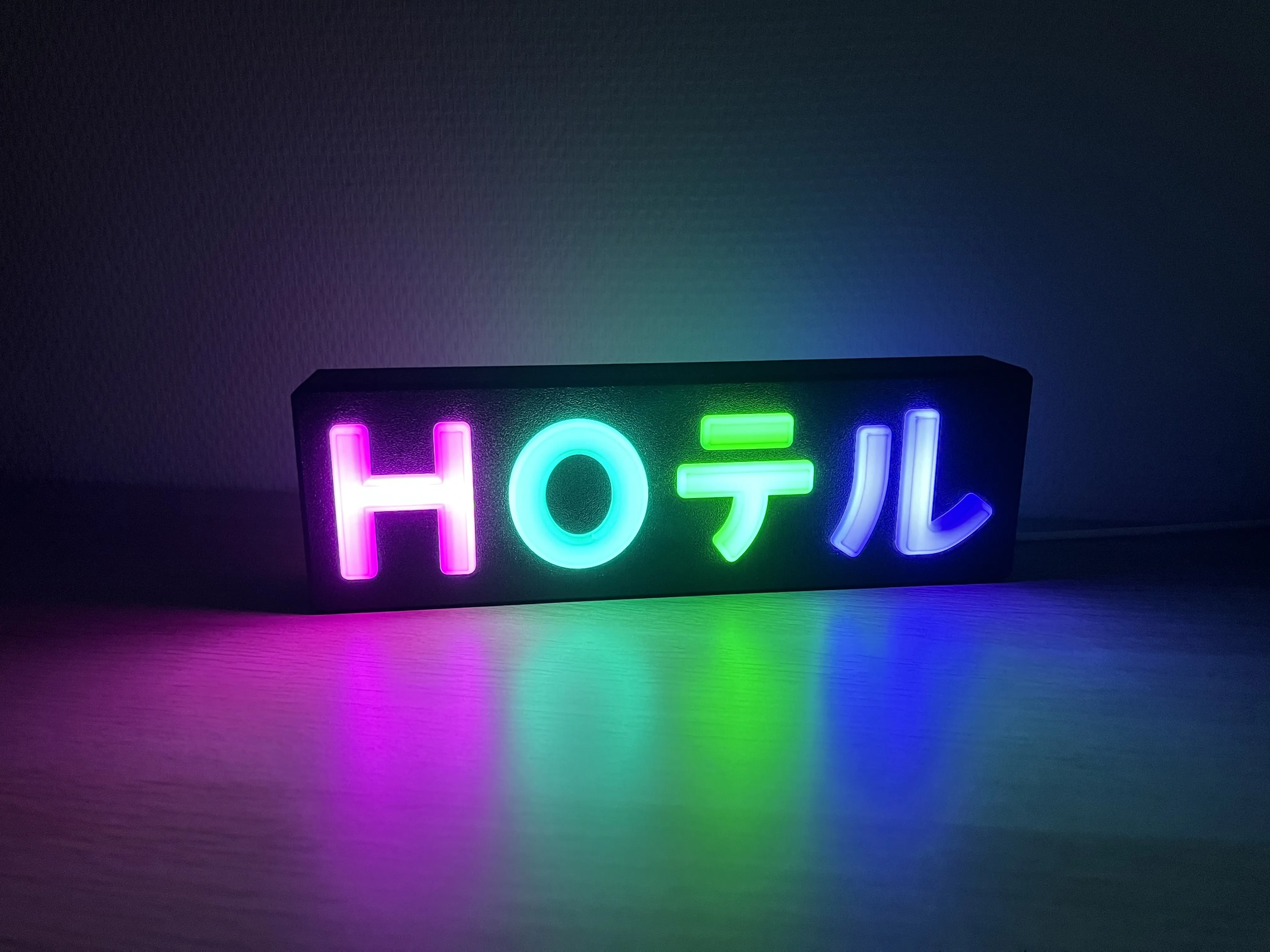
A HOテル Lamp powered by a USB-C ESP32 D1 Mini and four 4x4 WS2812B LED Matrices, running WLED for full RGB lighting control and an easy Home-Assistant integration.
This is the horizontal version of the lamp. An alternative vertical version is available here.
Featuring:
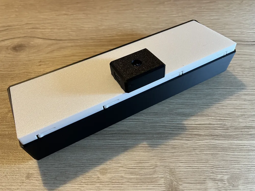
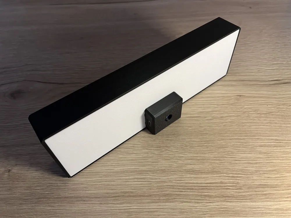
- Optional and reversible ESP32 D1 mini case (allows the USB-C connector to face left or right; removable if you prefer to drive the lamp with another controller).
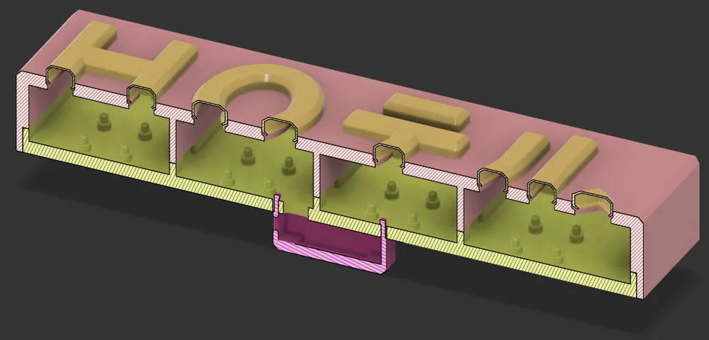
- Easy front and back plate assembly with print-in-place locking tabs and built-in supports.
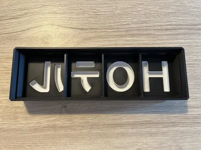
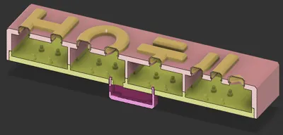
- Light-blocking walls on the front plate, enabling per-letter illumination with minimal light bleed.
Bill of Materials
The lamp was designed to fit the following components:
- USB-C ESP32 D1 Mini
- 30x30 mm, 4x4 WS2812B LED Matrix (4 total, one per letter)
You will also need:
- Wires
- 5cm x 12
- 13 cm x 3
- Optional: a small 3-pins connector (JST-XH 2.5 mm crimped connectors work well) to make assembly and disassembly easier.
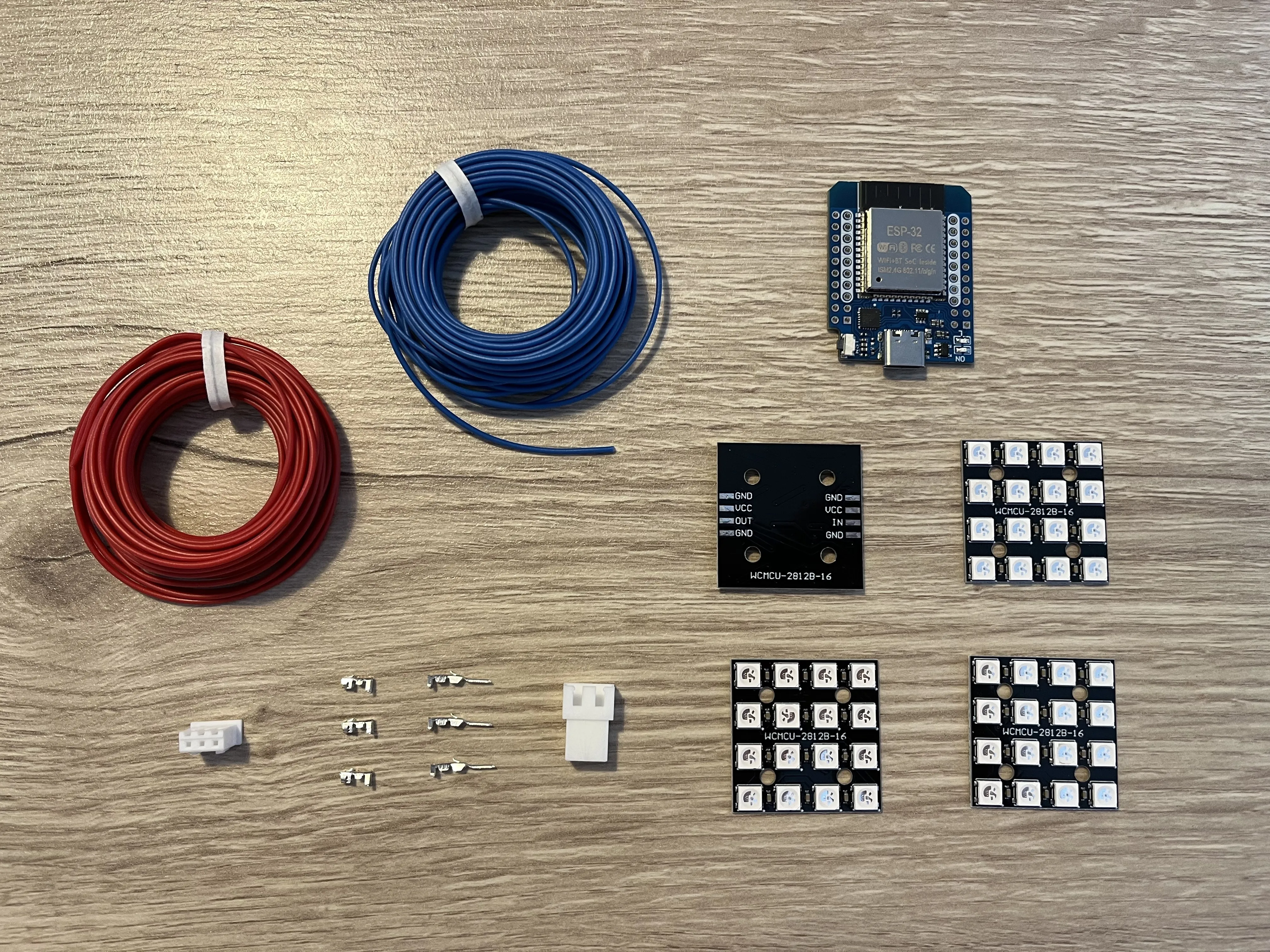
Printing recommandations
- The H, O, テ and ル light diffusers should be printed on a smooth build plate (smooth PEI or similar) using a light-diffusing color (e.g., white PLA). Using a textured plate will change the appearance of the letters, which might be desirable depending on the style you want.
- Do not enable slicer-generated supports, especially on the backplate, as they may interfere with the built-in model supports.
Instructions
1. Electronics
1.1. ESP32
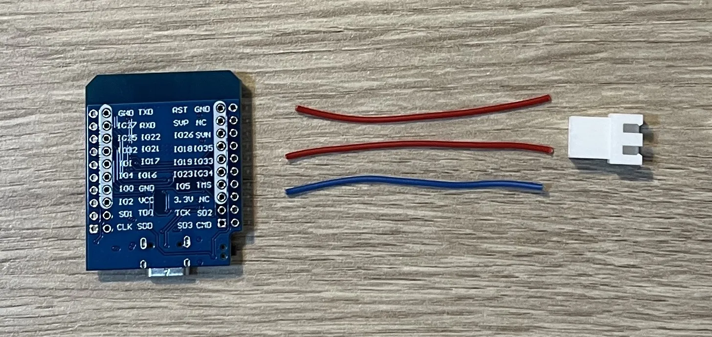
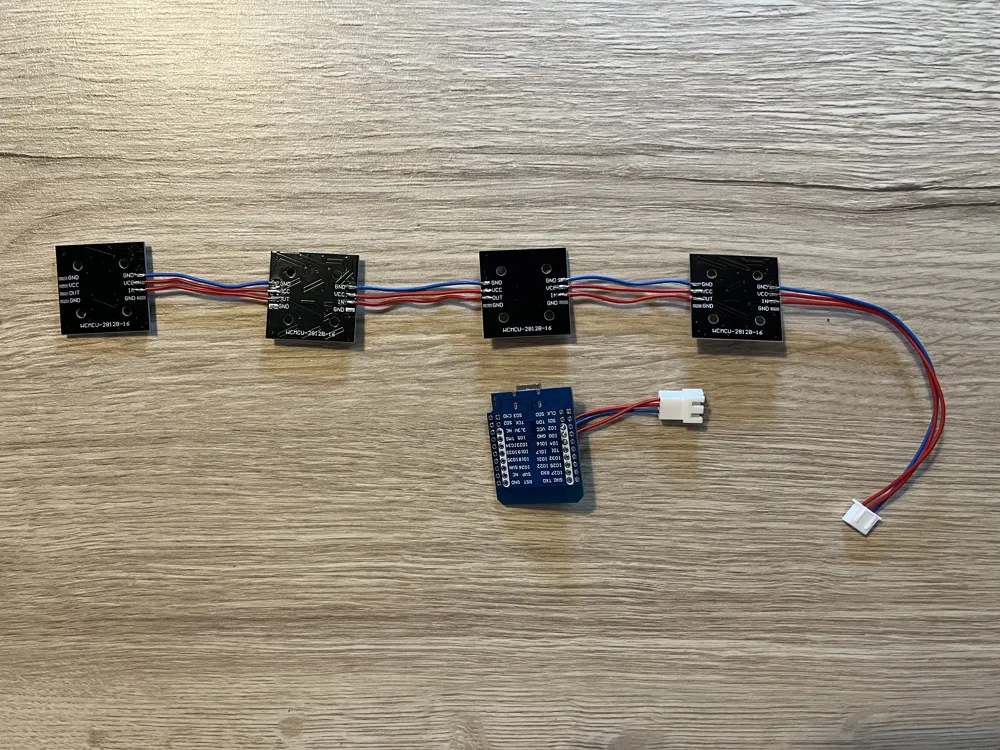
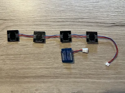
Solder three 5 cm wires to the ESP32 on the following headers:
- GND
- 5V
- IO16 (as recommended by the WLED documentation)
Then crimp or solder the wires to the JST-XH connector.
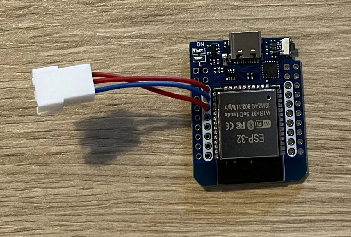
Finally, follow the official WLED documentation to install WLED on your ESP32:
- WLED installer site (recommanded method)
- WLED documentation
If your ESP32 is not recognized (no COM port), you may need to install the CP210x USB to UART driver.
1.2. LED matrices
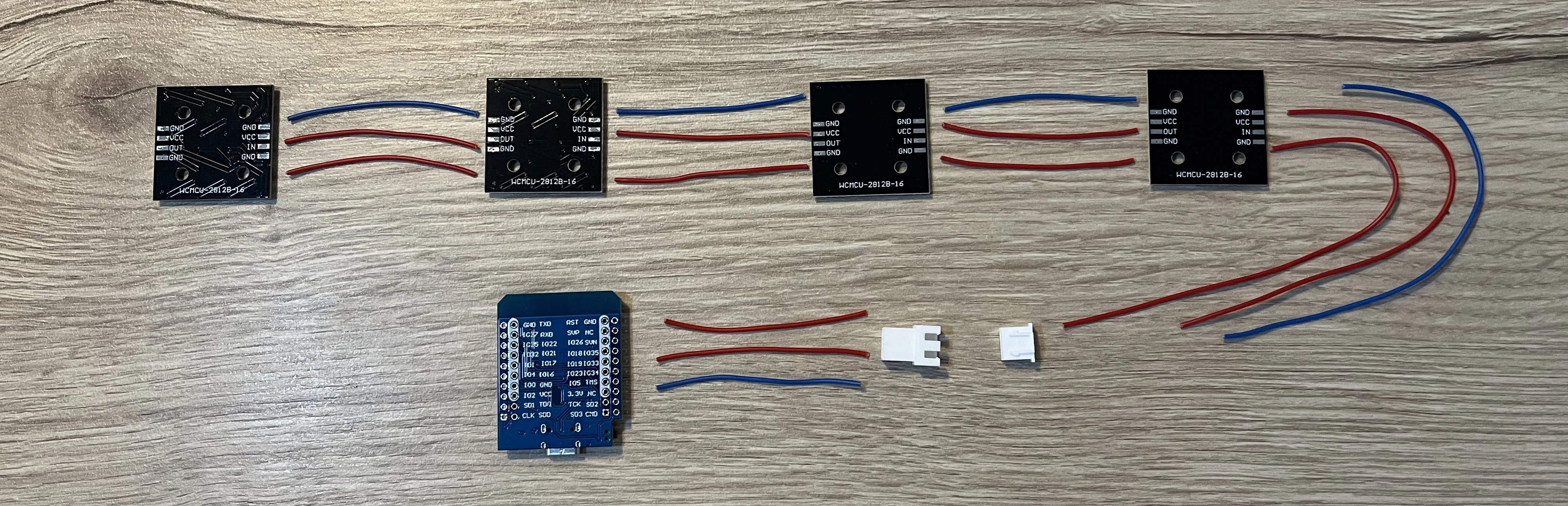
Solder the 4 LED Matrices in serie, using ~5 cm wires as follows:
- GND → GND
- 5V/VCC → 5V/VCC
- OUT → IN
On the first matrix (the one with the unsoldered IN pad), solder the three 13 cm wires to:
- GND
- 5V/VCC
- IN
Then crimp or solder the wires to the JST-XH connector, making sure to follow the pin order below so that, once both connectors are plugged together, the wiring matches properly:
- ESP32 GND → Matrix GND
- ESP32 5V → Matrix 5V/VCC
- ESP32 IO16 → Matrix IN
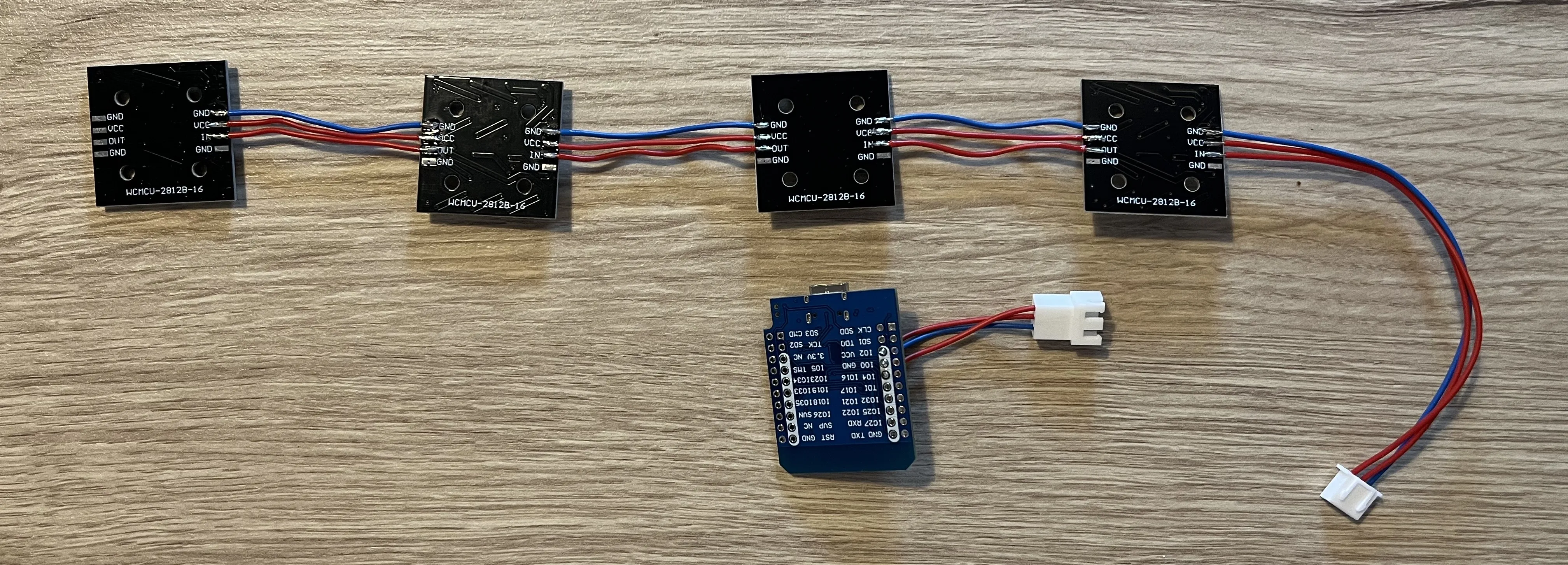
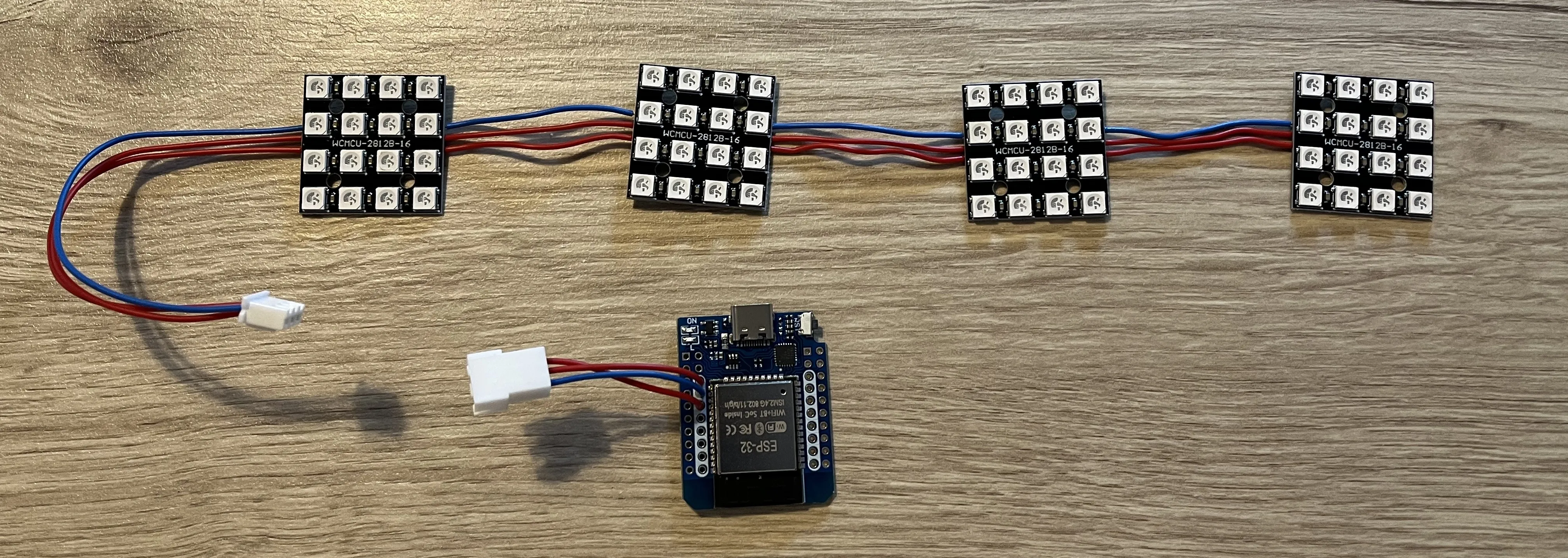
It’s a good time to check that everything is working properly by powering up the ESP32 and making sure everything behave as expected.
You may want to check the WLED configuration section below (Part 3.) if you want to test everything at this stage.
2. Lamp assembly
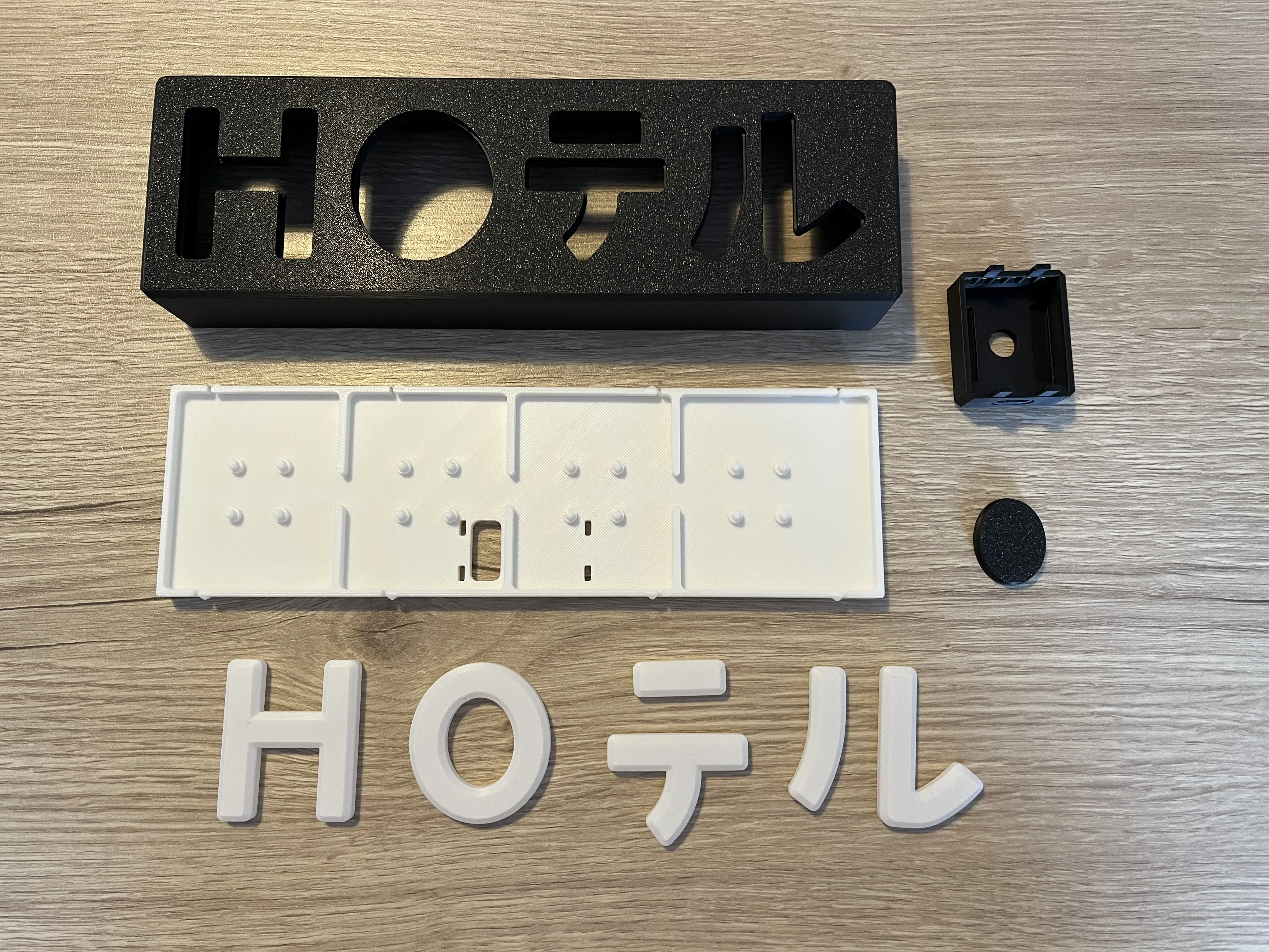
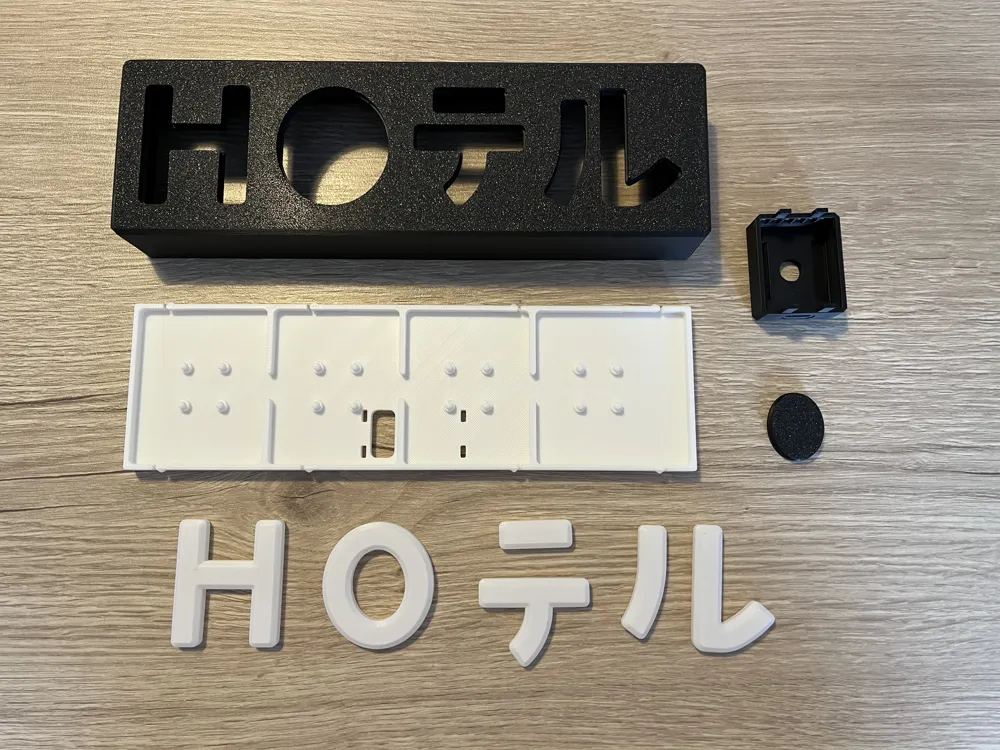
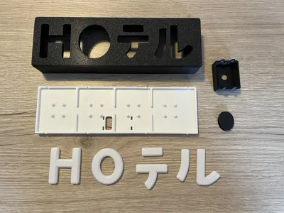
The lamp consists of:
- H, O, テ and ル light diffusers
- Frontplate (including the internal structure for the “O” letter)
- Backplate
- USB-C ESP32 D1 Mini mounting case
2.1. Front plate
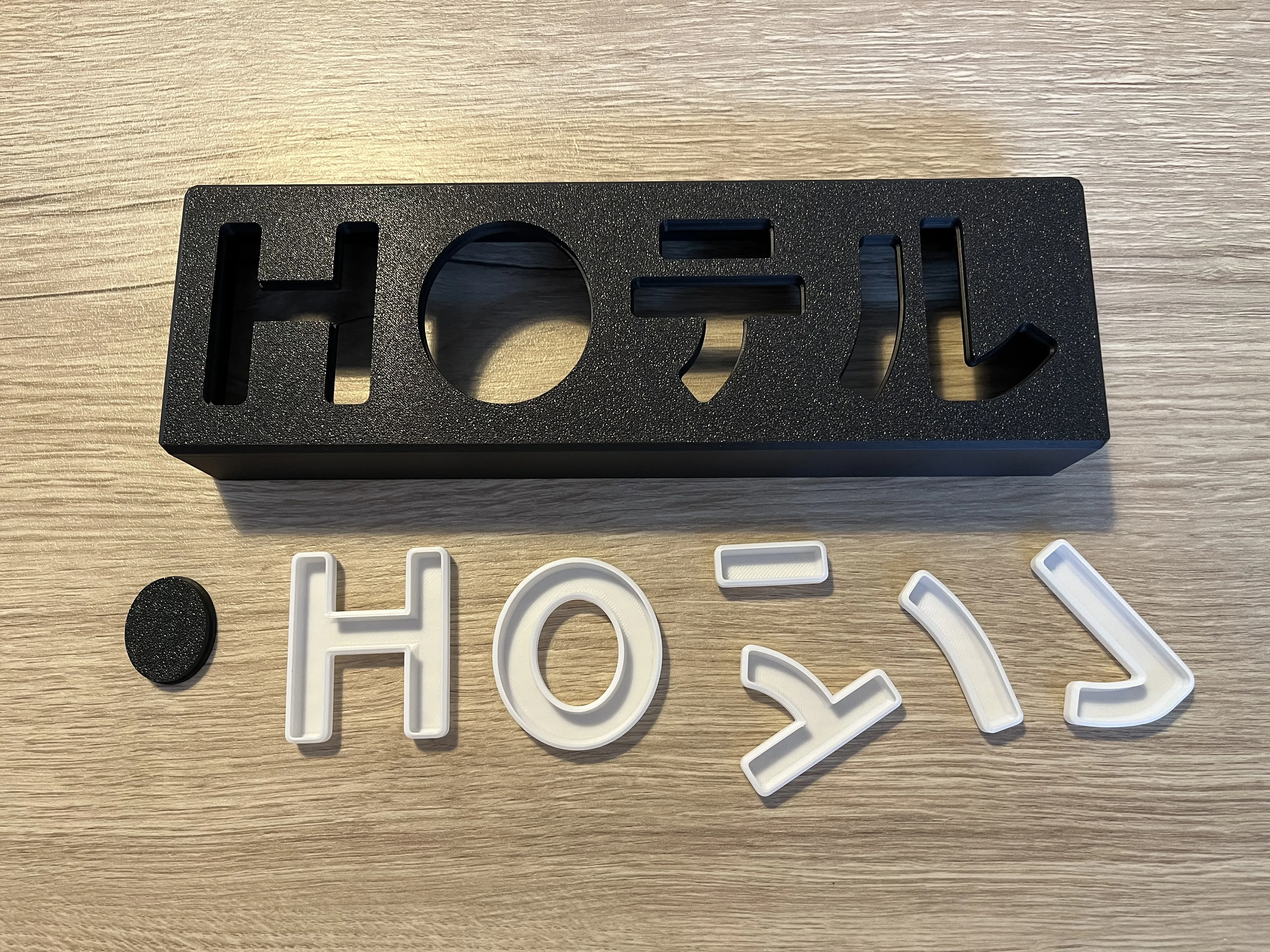
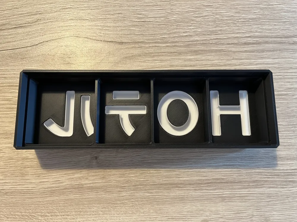
Start by clipping the inner part of the O into the O diffuser.
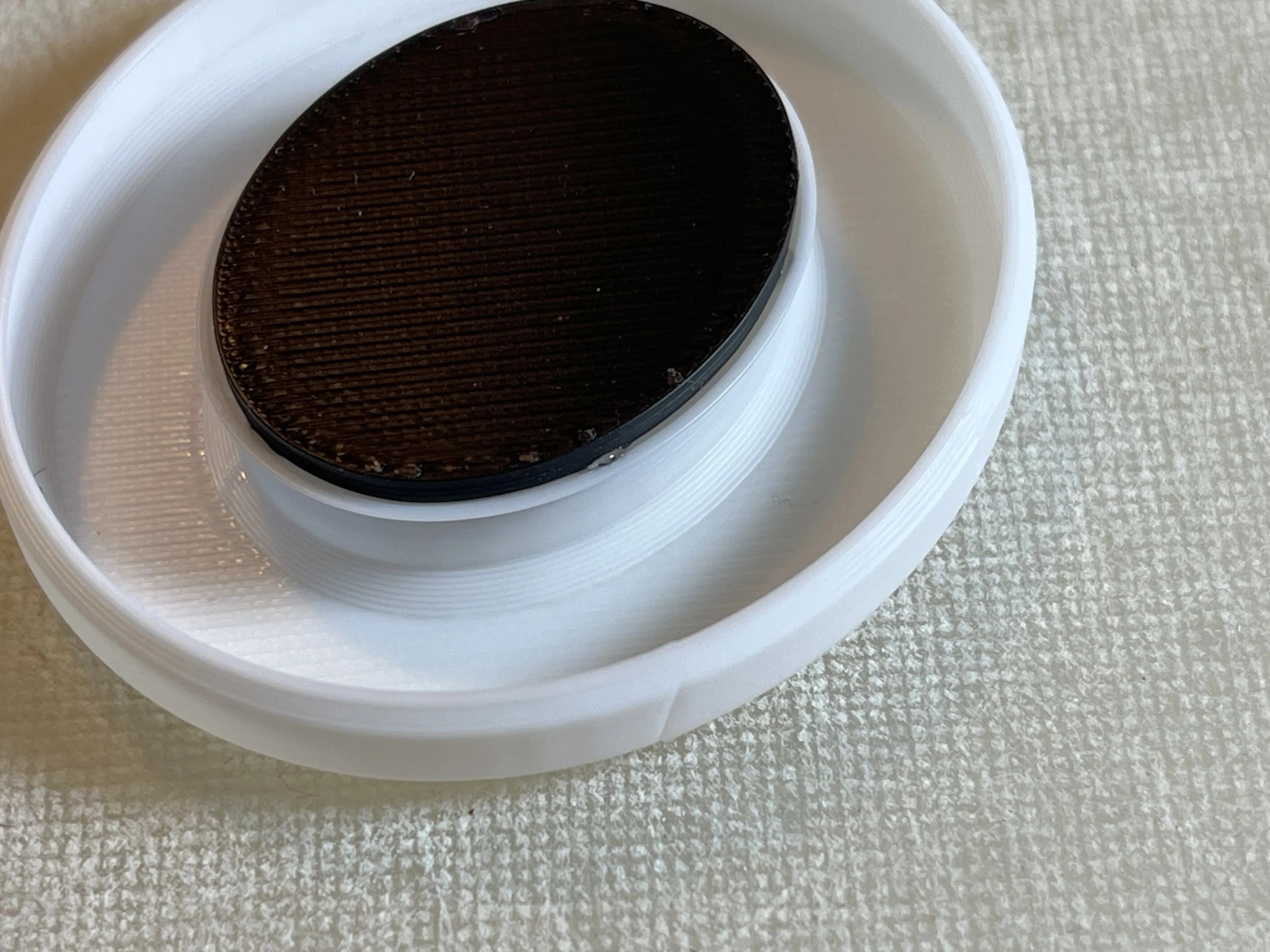
Depending on your printer’s tolerances or the filament used, you may need a small amount of glue. If so, only a few drops should be enough.
For easier assembly, apply the glue to the front plate groove, then press the diffuser into place.
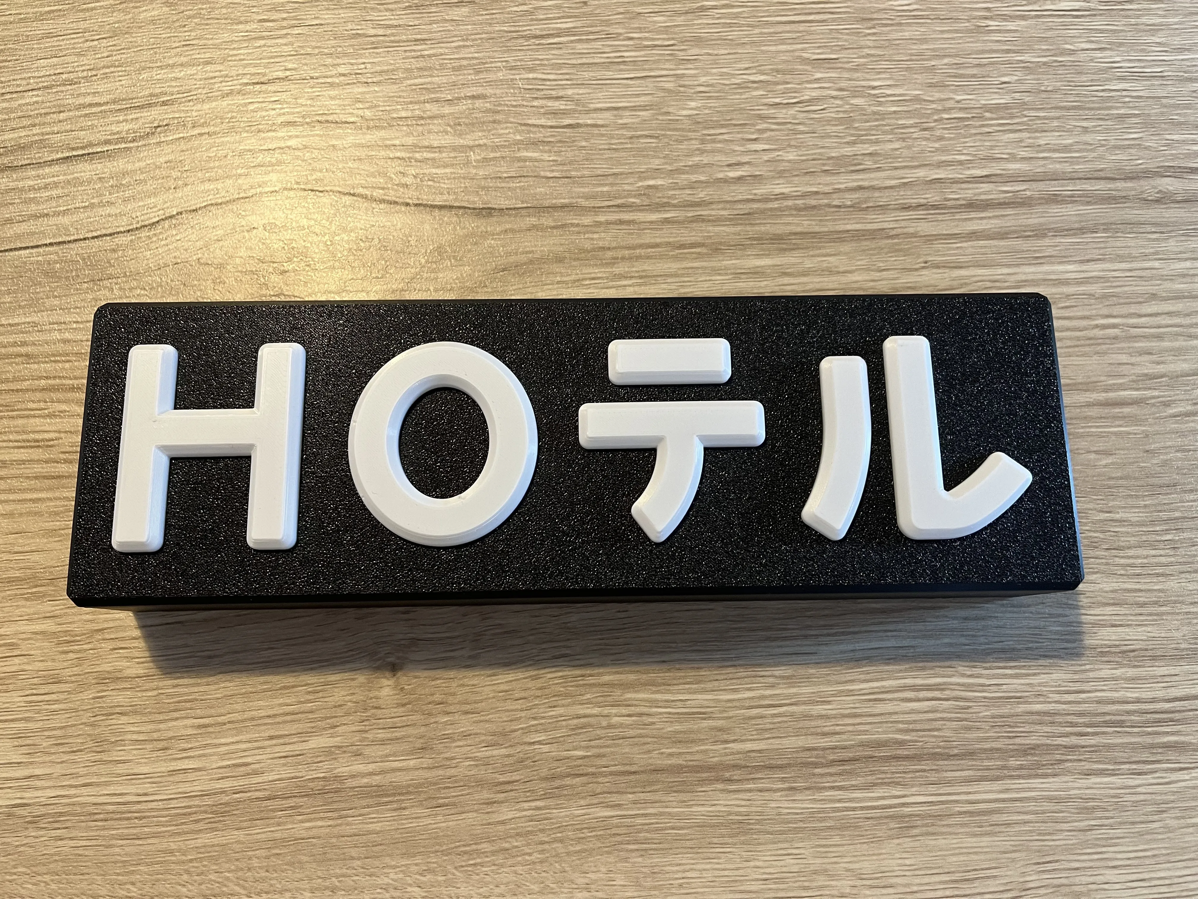
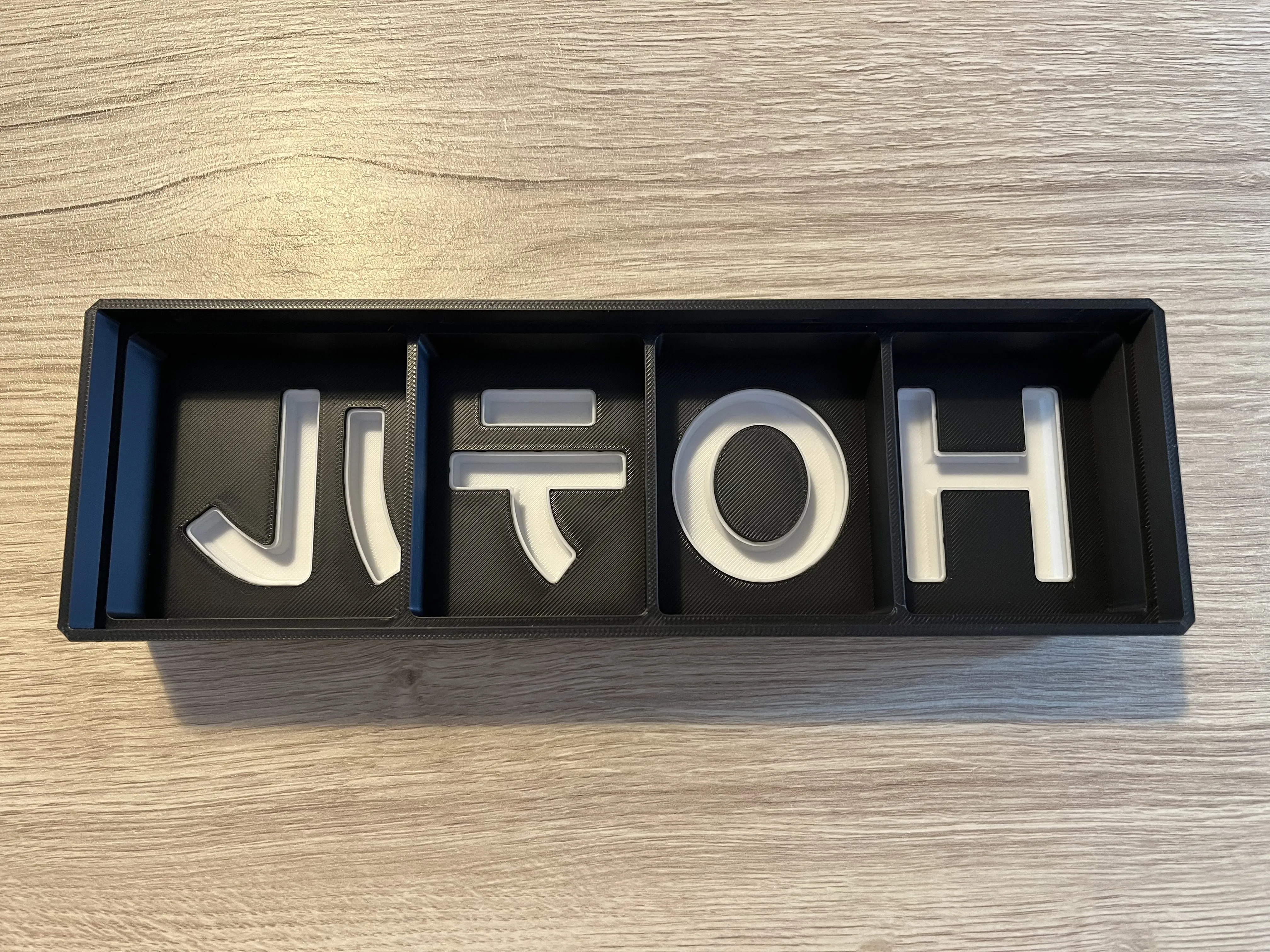
Assemble all the letters and katakana onto the front plate.
2.2. ESP32 case
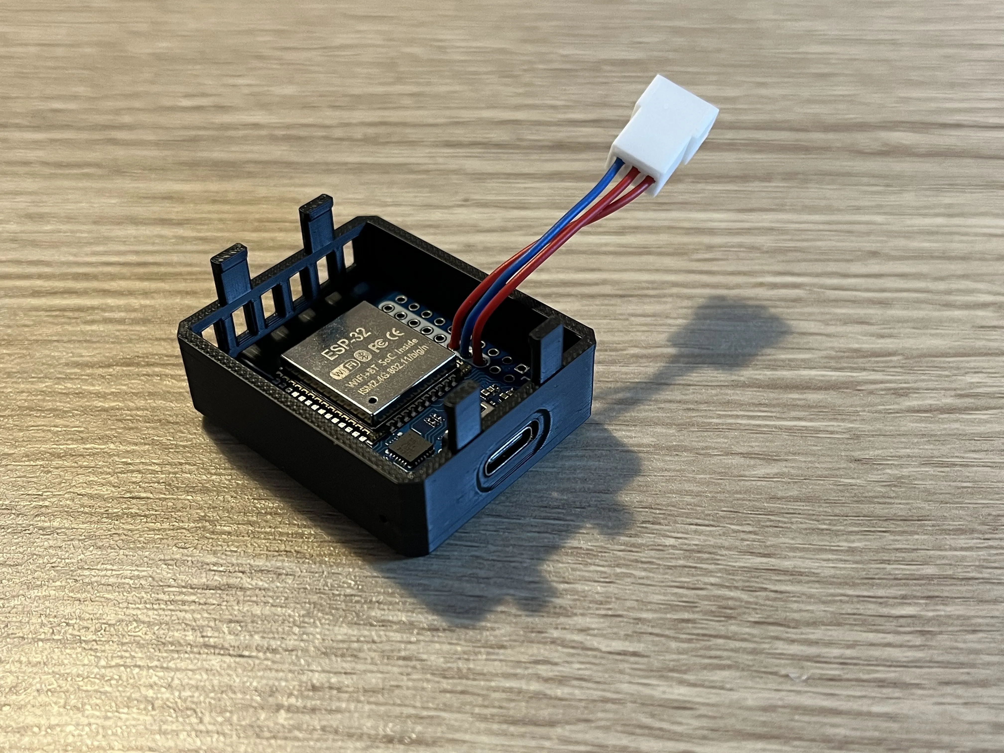
Mount the ESP32 into the mouting case.
Insert the USB-C connector first, then gently push the antenna side past the retaining clips.
2.3. Backplate
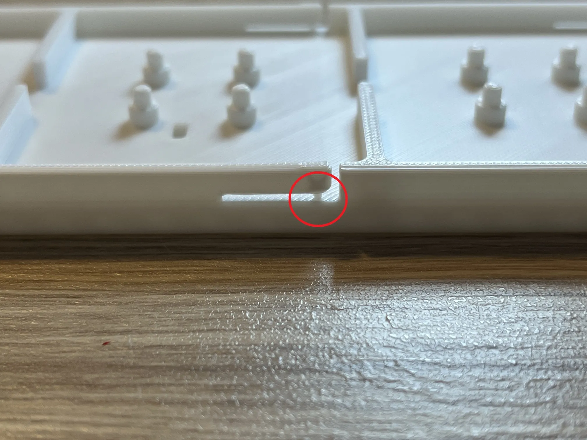
The backplate feature retention clips with in-model supports (~1 mm thick) that are meant to be broken during assembly. You can cut or break them off now. Once the supports are removed, the clips will gain a bit of flexibility.
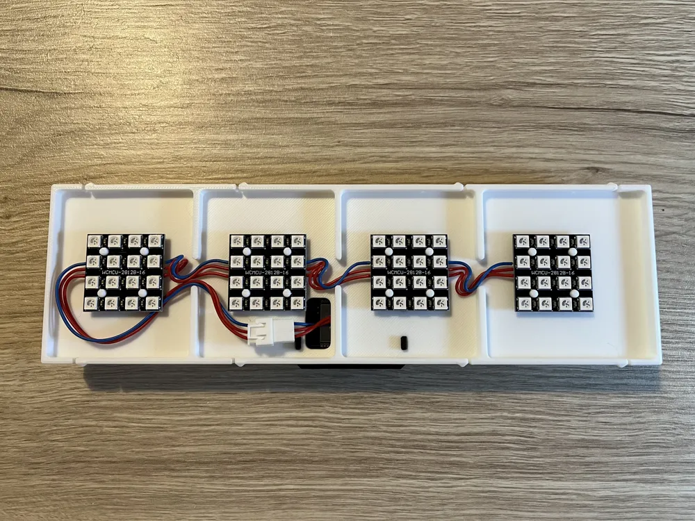
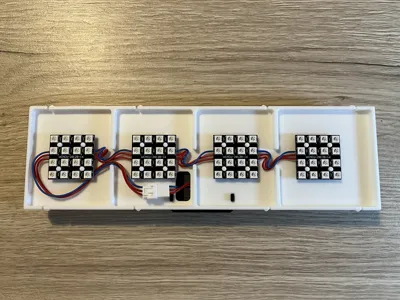
Mount all four LED matrices, from left to right, onto the back plate.
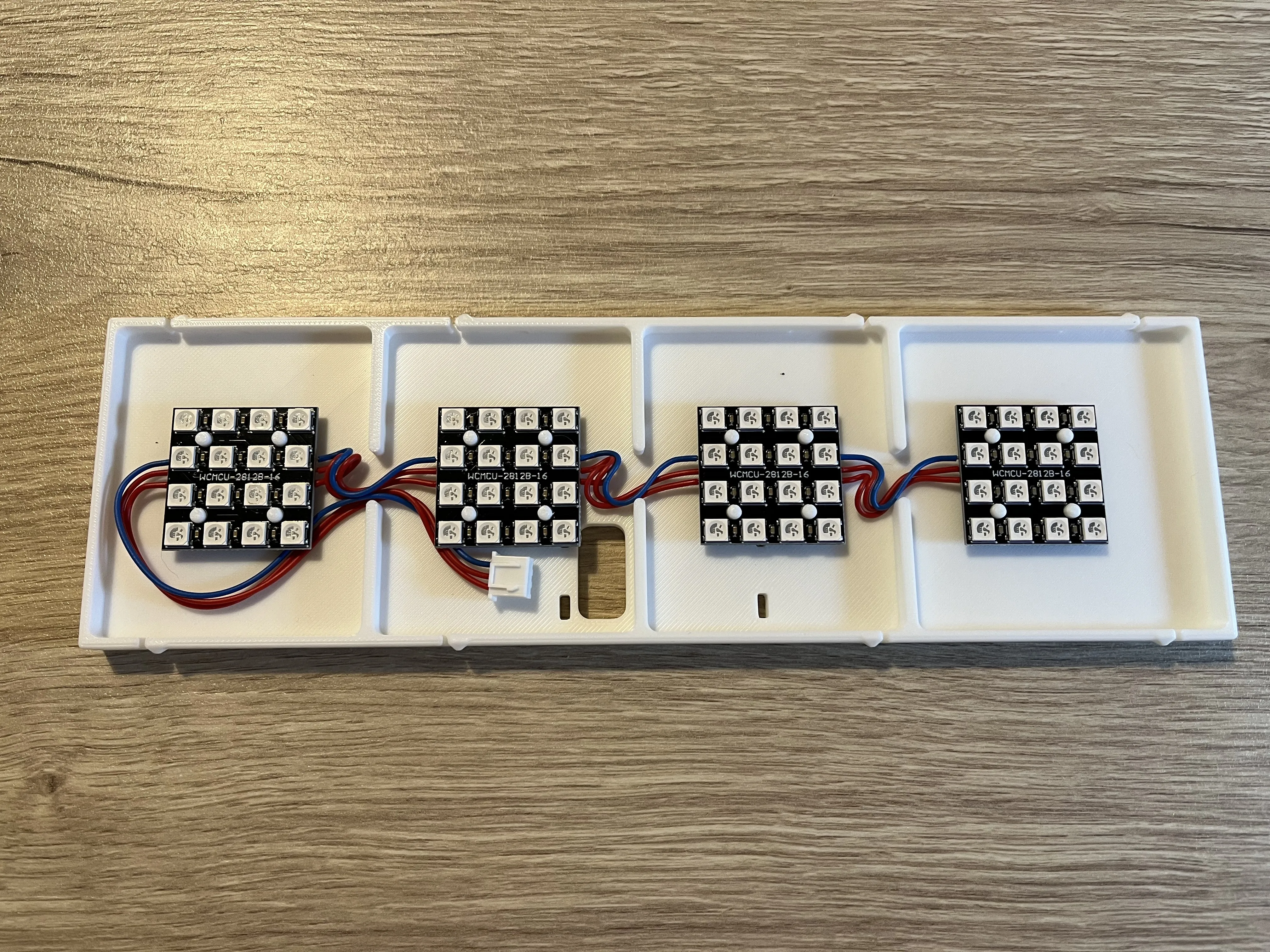
Push all the wires into the channels between the walls. These walls will later align with the light-blocking walls of the front plate, so make sure no wires remain in the way.
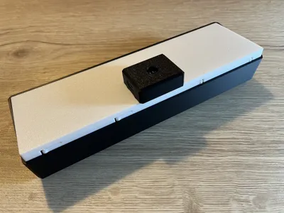
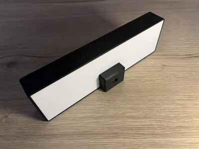
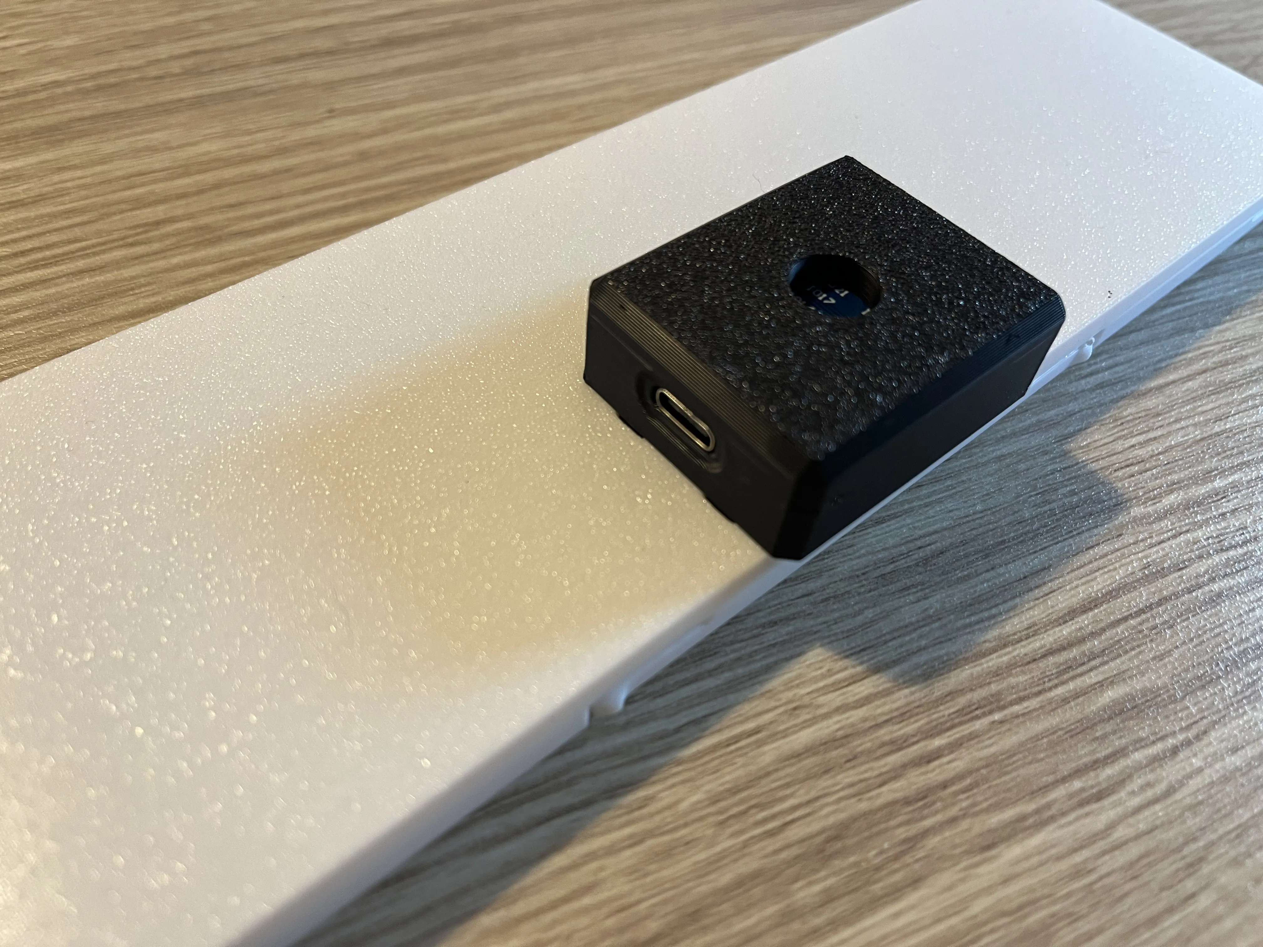
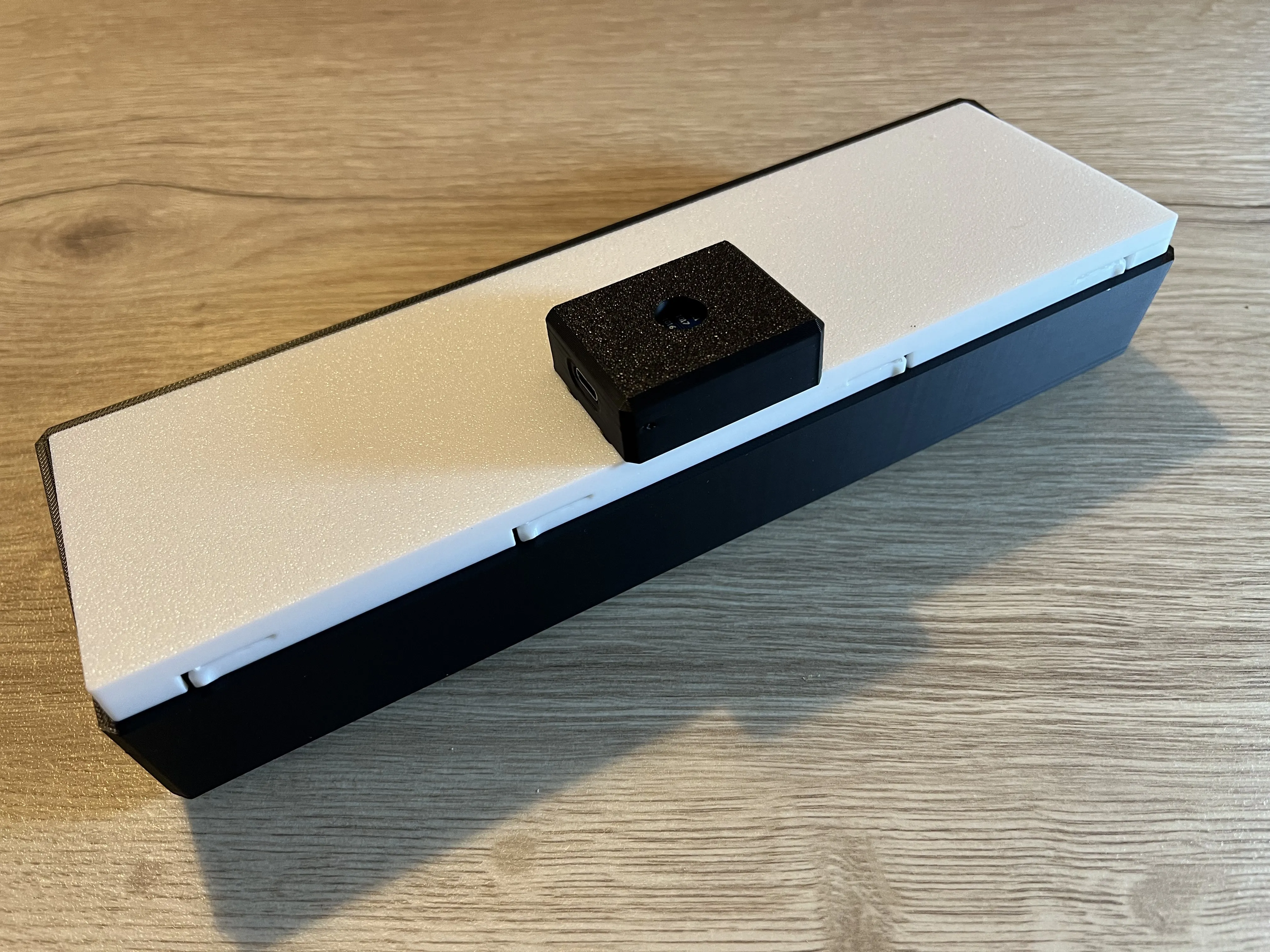
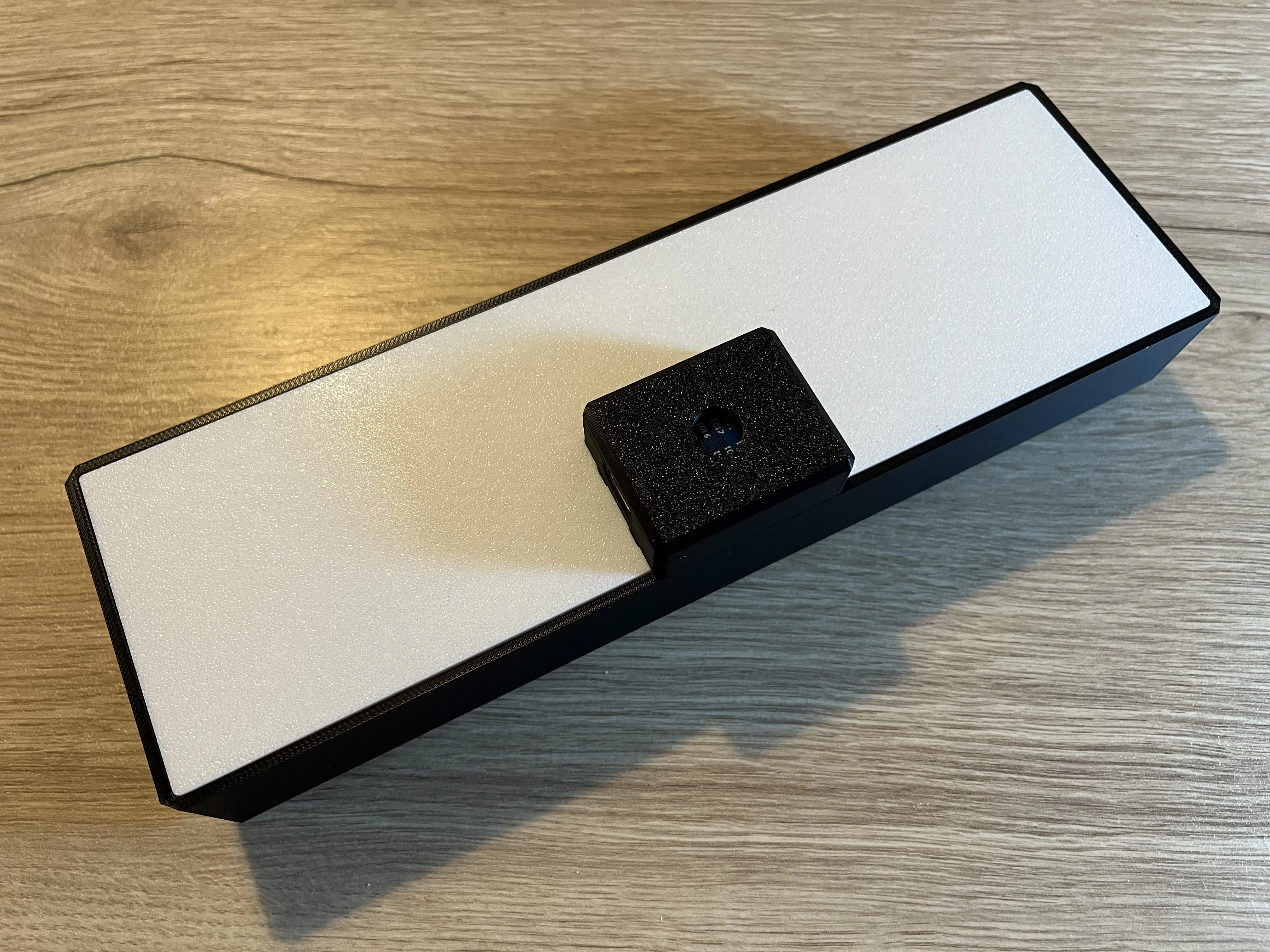
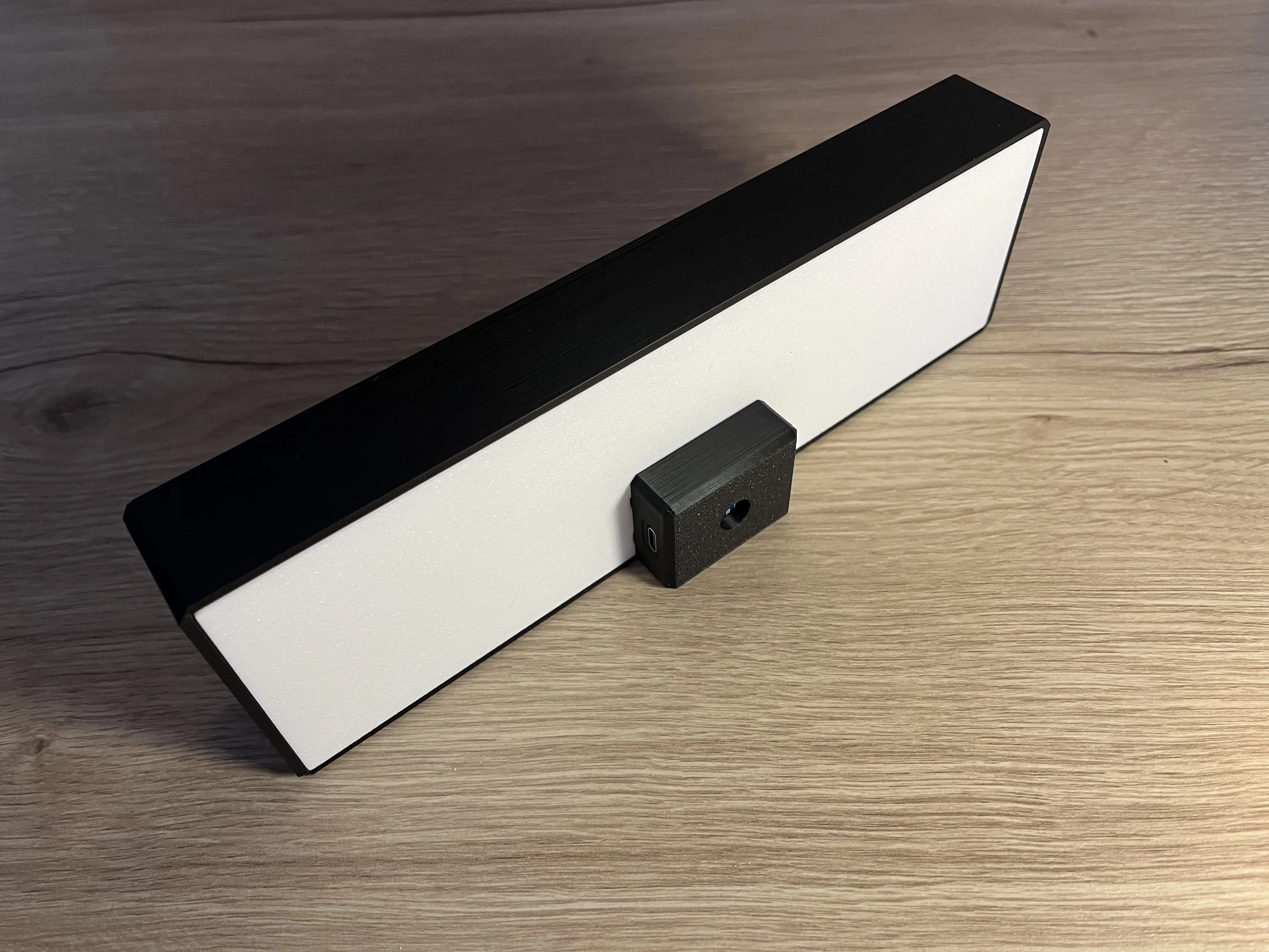
Clip the ESP32 mounting case onto the back of the backplate, ensuring that the connector passes through the hole designed for it.
It’s normal if the ESP32 doesn’t align at this stage: it will once the frontplate is installed.
You can choose to orient the USB-C connector to the left or to the right, depending on your preference.
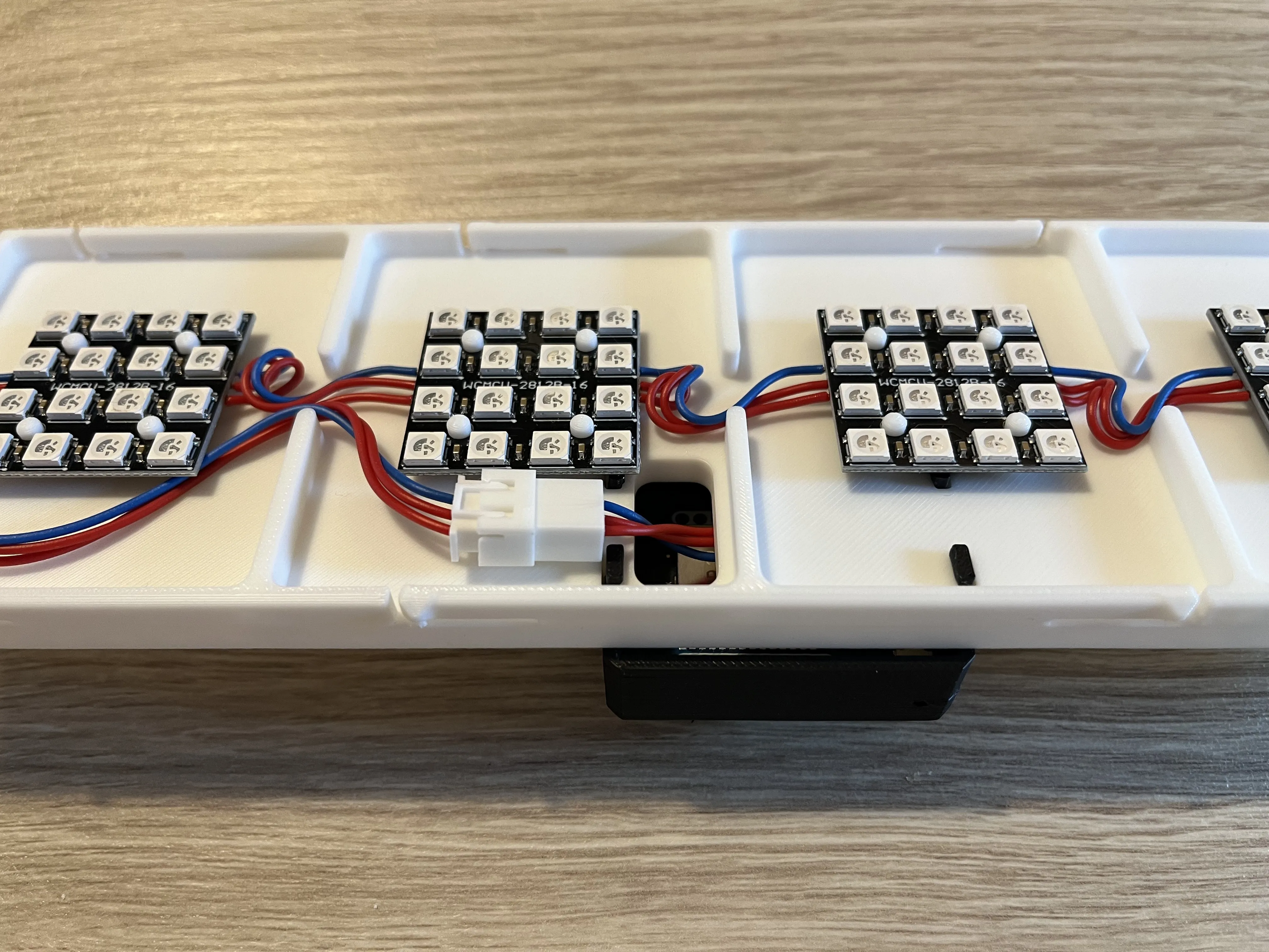
You can now connect both ends of the JST-XH connector.
2.4. Final assembly
The backplate clips onto the front plate. Just make sure that the ESP32 ends up at the base of the lamp once everything is assembled.
3. WLED configuration
3.1. LED Preferences
In the WLED LED & Hardware menu, you should configure:
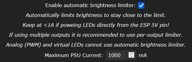
- Enable automatic brightness limiter: Enabled (since the LED matrices are powered from the ESP32’s 5V line)
- Maximum PSU Current: 1000mA
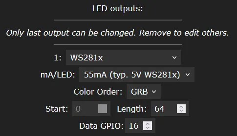
And under the Hardware Setup, set:
- Length: 64
- Data GPIO: 16
3.2. 2D Configuration
Under the WLED 2D Configuration, you can generate the matrix layout using the built-in panel generator with the following settings:
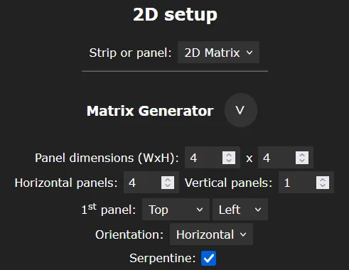
- Strip or panel: 2D Matrix
- Panel dimensions: 4 x 4
- Horizontal panels: 4
- Vertical panels: 1
- Orientation: Horizontal
- Serpentine: Yes (was the case for the panels referenced in the bill of materials).
3.3. Segments
Once the matrix is configured, you can easily create segments for each letter, allowing you to assign different colors or effects to each letter or katakana:
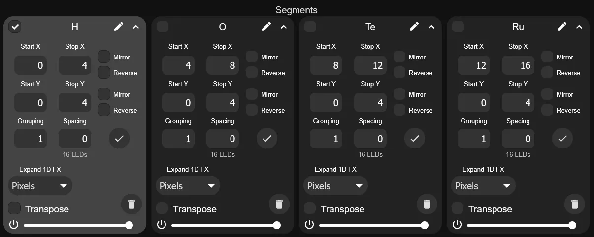
- Segment “H”
- Start X: 0
- Stop X: 4
- Segment “O”
- Start X: 4
- Stop X: 8
- Segment “テ” / “Te”
- Start X: 8
- Stop X: 12
- Segment “ル” / “Ru”
- Start X: 12
- Stop X: 16
Once the segments are created, you can assign colors and effects to each one individually.
4. Home-Assistant integration
This lamp can easily be integrated into Home Assistant or any WLED-compatible automation setup.
You might be especially interested in:



Comment & Rating (1)