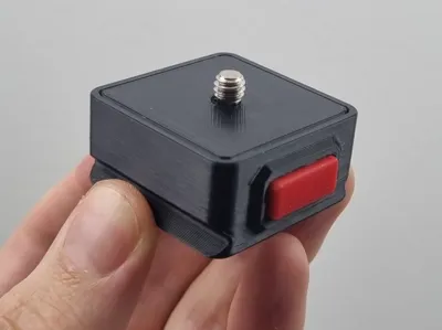
Camera Snap Fit Quick Release Plate and Mount


Print Profile(1)

Bill of Materials


Description
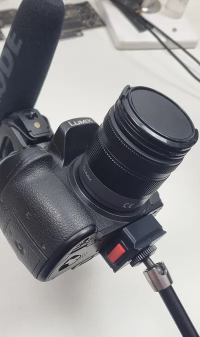
This model is inspired by quick release systems made by brands like ulanzi, smallrig, neewer etc.
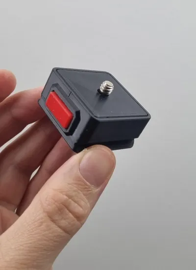
It is snap fit and only requires pressing the buttons on both sides to release the plate.
This model is only tested with ASA, your results may vary with other filaments due to differences in stiffness. It should work with PLA and PETG but I do not know if the spring will feel the same.
I recommend using my print profile, as it has all the necessary settings already set.
Hardware required:
- 4x M3 6mm countersink screws (3mm to 6mm works)
- 4x M3 heat inserts (maximum length 6mm)
- 1x ¼ inch camera screw 16mm x 16mm x 10mm - Link
Assembly notes:
Make sure that the buttons can pass through the holes with no effort, they should fall off if you let them slide out before assembly. Due to the supported part above the button hole, you might need to clear any filament left from the bridging. The design has lower tolerance for that part but your results may vary. The easiest way to clean up bridges for me is with a file.
- The screws must fit flat in the countersink hole designed for them, otherwise, the quick release plate won't fit.
Assembly:
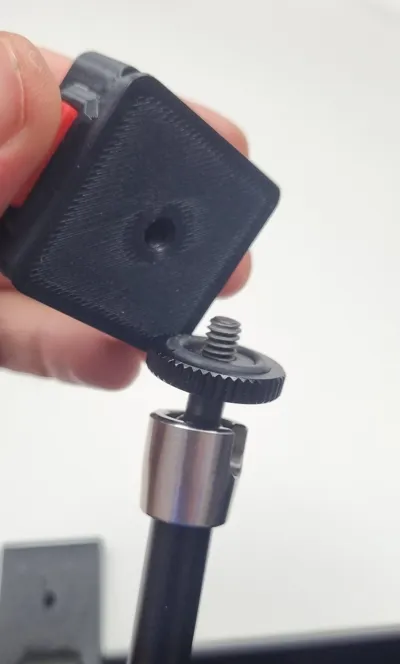
- 1. Screw in the ¼ inch screw in the quick release plate. The thread will keep it from falling.

2. Insert the heat inserts in the 4 holes of the main body

3. Position the spring and the 2 buttons in place, make sure they can pass through the holes with no effort. This is important for later.


4. Position the fixing plate on top by squeezing the buttons to let it fit in place

5. Screw the 4x M3 screws


License
You shall not share, sub-license, sell, rent, host, transfer, or distribute in any way the digital or 3D printed versions of this object, nor any other derivative work of this object in its digital or physical format (including - but not limited to - remixes of this object, and hosting on other digital platforms). The objects may not be used without permission in any way whatsoever in which you charge money, or collect fees.
Comment & Rating (10)