
AMS lite A1 Top-Mount Bracket (Numbers Upright)
Print Profile(1)

Description
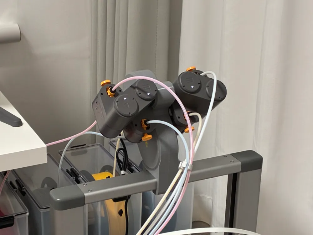
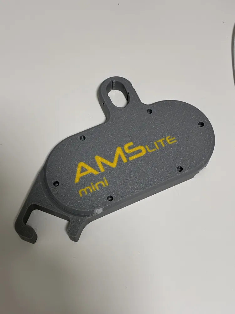
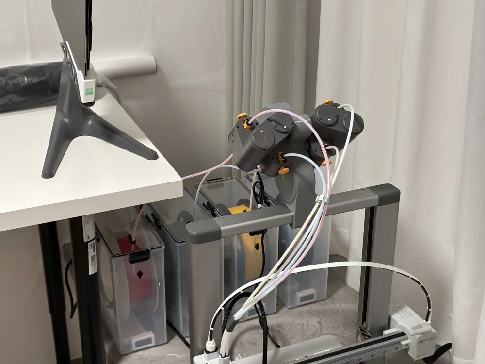
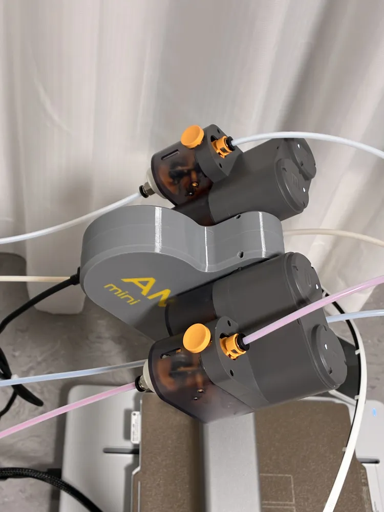
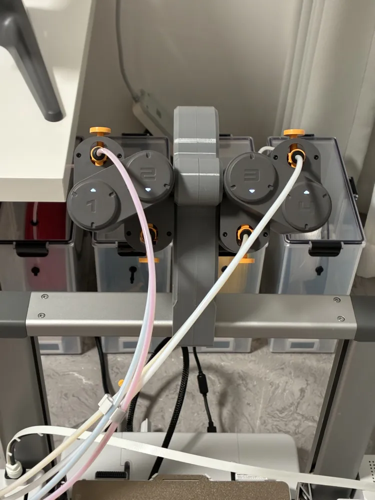
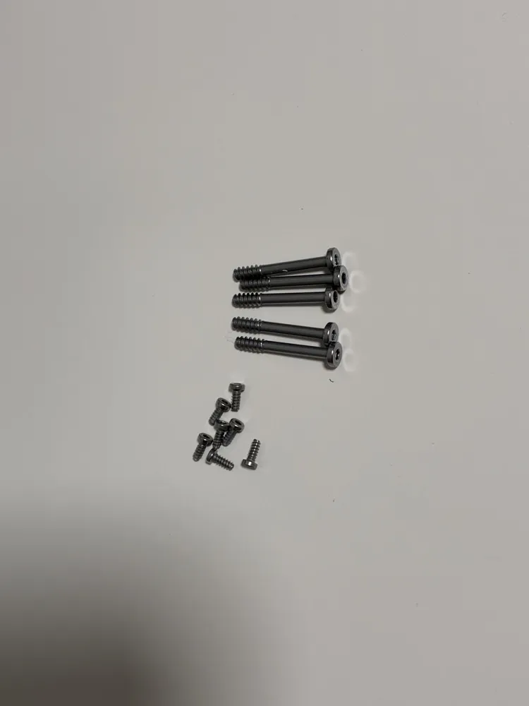
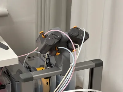
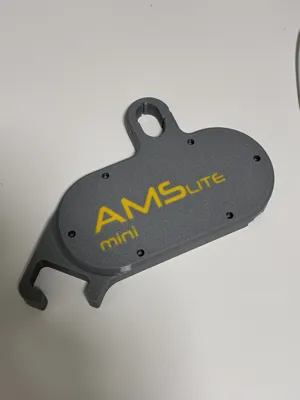
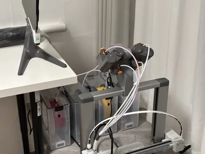
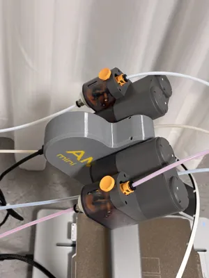
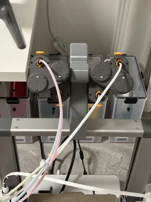
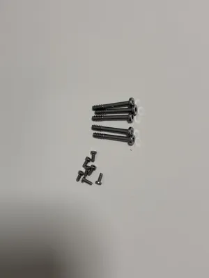
I referred to many top-mount solutions for AMS Lite, but none of them met my needs. So I made one myself that can be printed in a single batch. It’s easy to install—just clip it directly onto the A1 gantry, and it’s extremely stable. All the screws are taken from the AMS Lite: the longer ones are used to fasten the shell, while the shorter ones are for the feeder module and the mainboard.
⚠️⚠️ Installation Notes! Be sure to follow the installation sequence! ⚠️⚠️
- Disassemble the AMS Lite (refer to the official Wiki for specific disassembly and assembly instructions).
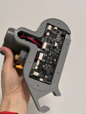
- Insert the "1, 2" feeder modules into the left shell (make sure not to reverse them), and fasten them with two small screws.
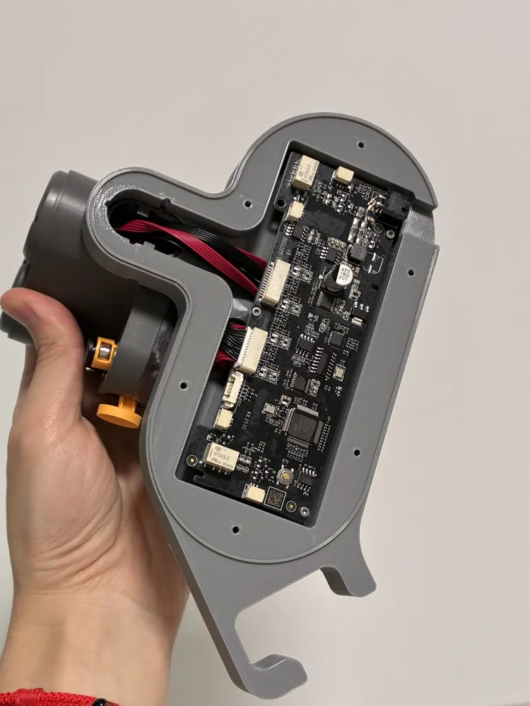
- Arrange the red flat cable, connect it to the mainboard, and secure the mainboard with three small screws.
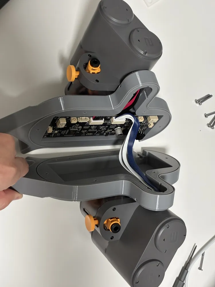
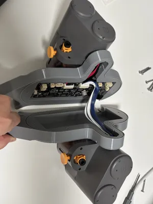
- Insert the "3, 4" feeder modules into the right shell (make sure not to reverse them). ⚠️⚠️ Do NOT fasten the screws yet! ⚠️⚠️
- Connect the blue flat cable and tidy up all the wiring harnesses.
- Use six long screws to join the two shells together.
- Fasten the "3, 4" feeder modules with two small screws.
I referred to many AMS lite top-mount solutions, but couldn't find one that met my needs. So I made one myself that can be printed in a single plate. It's easy to install, just clips directly onto the A1 gantry, and is extremely stable (all screws are taken from the AMS lite: the longer ones are for fastening the shell, and the shorter ones are for fastening the feeder module and the mainboard)
⚠️⚠️ Installation Notes! Be sure to follow the installation sequence! ⚠️⚠️
Step 1: Disassemble the AMS lite (refer to the official Wiki for specific disassembly and assembly instructions)
Step 2: Insert the '1, 2' feeder modules into the left shell (make sure not to reverse them), and fasten them with two small screws
Step 3: Arrange the red flat cable, connect it to the mainboard, and secure the mainboard with three small screws
Step 4: Insert the '3, 4' feeder modules into the right shell (make sure not to reverse them). ⚠️⚠️ Do NOT fasten the screws yet! ⚠️⚠️
Step 5: Connect the blue flat cable and tidy up all the wiring harnesses
Step 6: Use six long screws to join the two shells together
Step 7: Fasten the '3, 4' feeder modules with two small screws
License



Comment & Rating (3)