
2" Telescope Focuser (Compression Ring + Adapter)
Print Profile(1)

Description
A Maker World first! (As far as I can tell). I looked long and hard for something like this, but nothing suited my needs, so I designed my own. There are some good Crayford designs on the web, but require lots of hardware I didn't have.
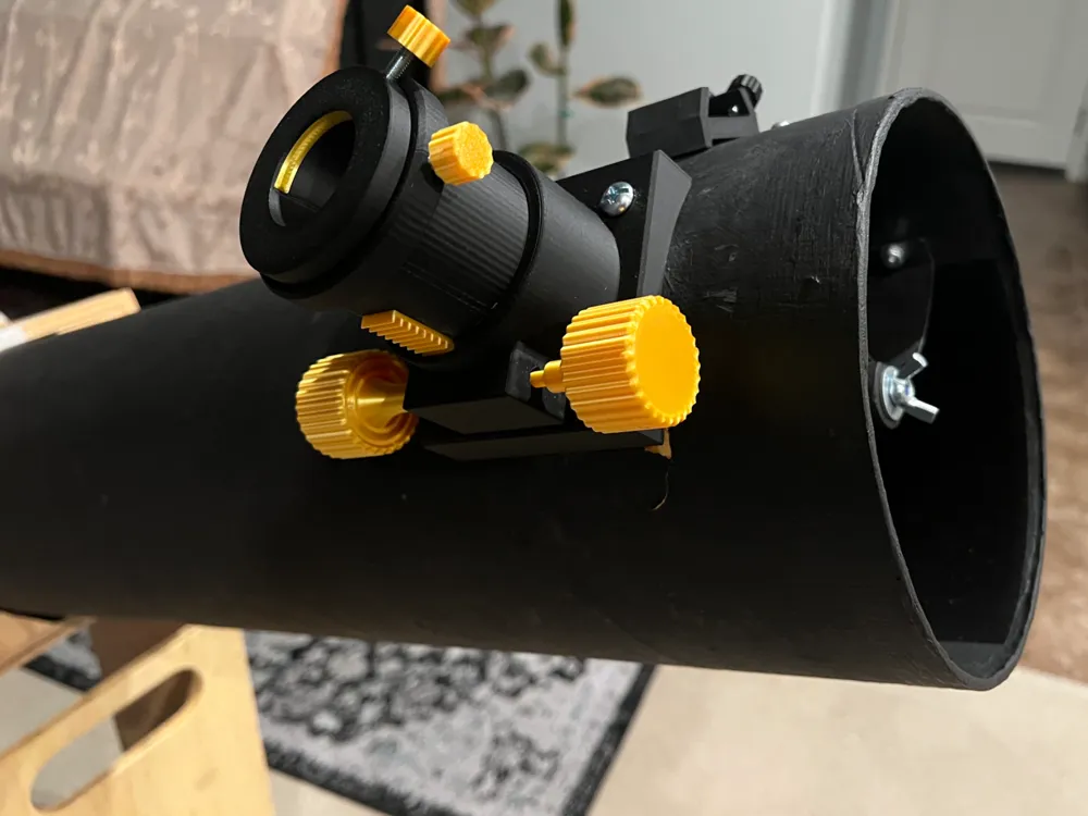
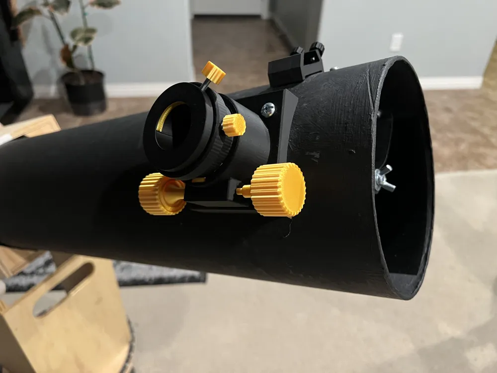
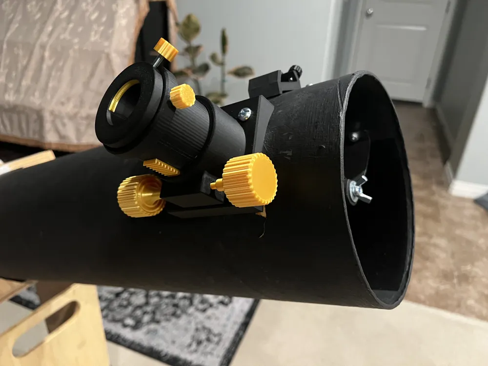
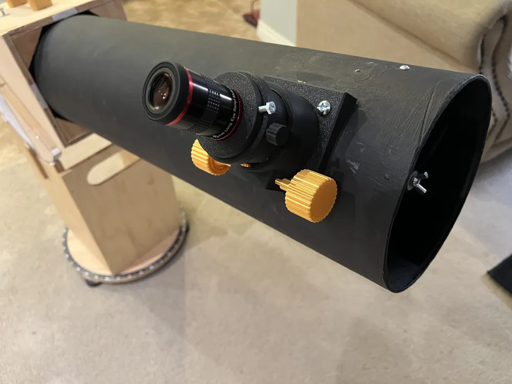
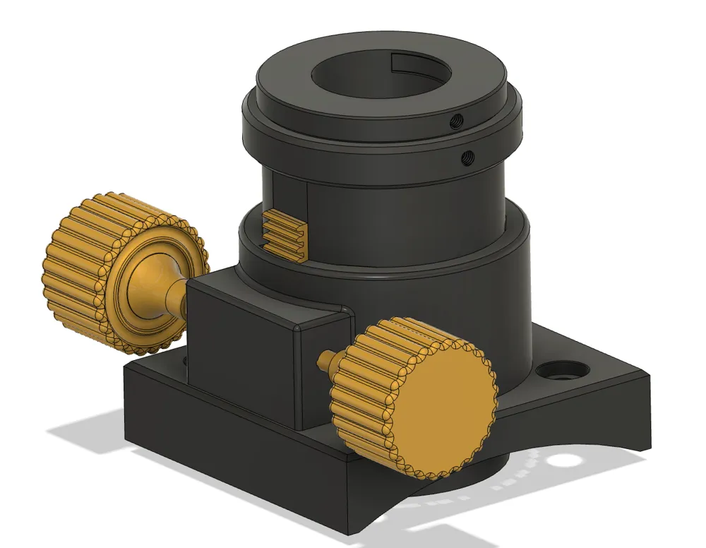
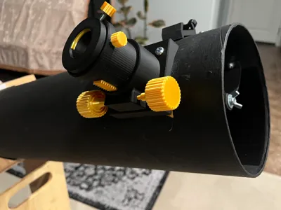
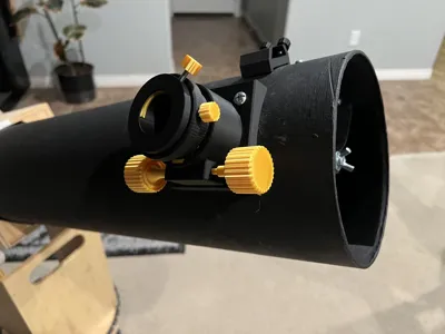
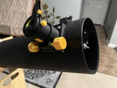
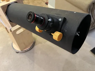
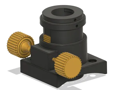
Here we have a 2" rack and pinion telescope focuser for Newtonian reflectors, complete with a 2" to 1.25" eyepiece adapter, AND with compression ring locking mechanisms on the drawtube and the adapter. There's an optional hole for a drawtube lock screw. At minimum height it's just under 2.5" above the outside of the tube, and it has over 2" of travel. There is a mechanism that blocks the tube from sliding out completely.
Best of all, the focuser mechanism itself requires NO HARDWARE! If desired, M4 hex head screws are recommended for locking the eyepiece. The knurled lock knobs for M4 screws is another of my designs, also on Maker World.
This took many iterations and lots of time! Please consider giving a boost if you liked this design.
Important dimensions for compatibility:
- Drawtube largest dimension: 2.3" (OTA hole must be larger)
- Base mounting screws: ¼-20 (smaller may work)
- Mounting screw placement: 2.25" x 2.25"
- Base curve diameter: 7.7" (ideal for 6" reflectors, else may need shims)
Printing notes:
Various slicing settings have been modified. The second plate contains the rack and pinion mechanism, knobs, bearing rails, and compression rings, which for aesthetic purposes I printed out of silk PLA, and hence for some objects used 50mm/s outer wall speed. The pinion is small so line width was reduced. I recommend printing another axle / shaft as it is the weakest link. I recommend printing the second plate with the 4 bearing rails/shims on a smooth PEI plate for lowest friction. You could try ironing but I haven't tested this.
Assembly instructions:
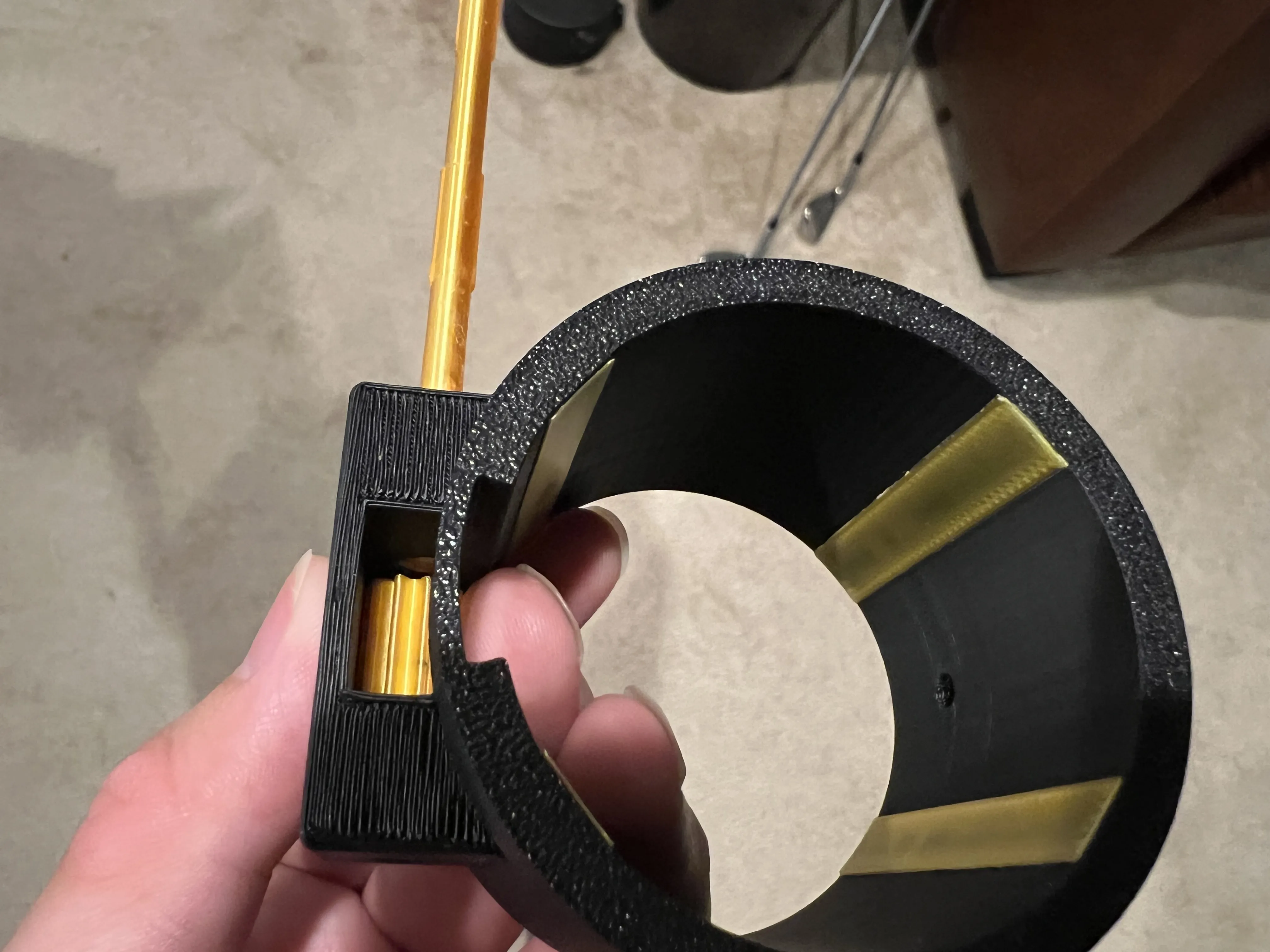
Once all the parts are printed, I used double sided tape to secure the bearing rails to the guide tube. CA glue works also. Make sure the smooth side faces inward.
Position the gear into the housing as shown. Make note of the protrusions on the axle. These go into the notches in the pinion gear so that in case the glue fails, the pinion still rotates with the axle. Make note of the notch orientation and slide the axle through the holes in the guide tube, through the gear, and out the other side. This is the trickiest step: it may take several tries. The axle rotates freely when the protrusions are completely inside the walls of the gear housing.
Glue isn't strictly necessary but otherwise you'll have backlash. Unfortunately there's not much room, so you'll have to wiggle the gear and axle to get the glue in it. CA glue will work, but epoxy is a more permanent solution.
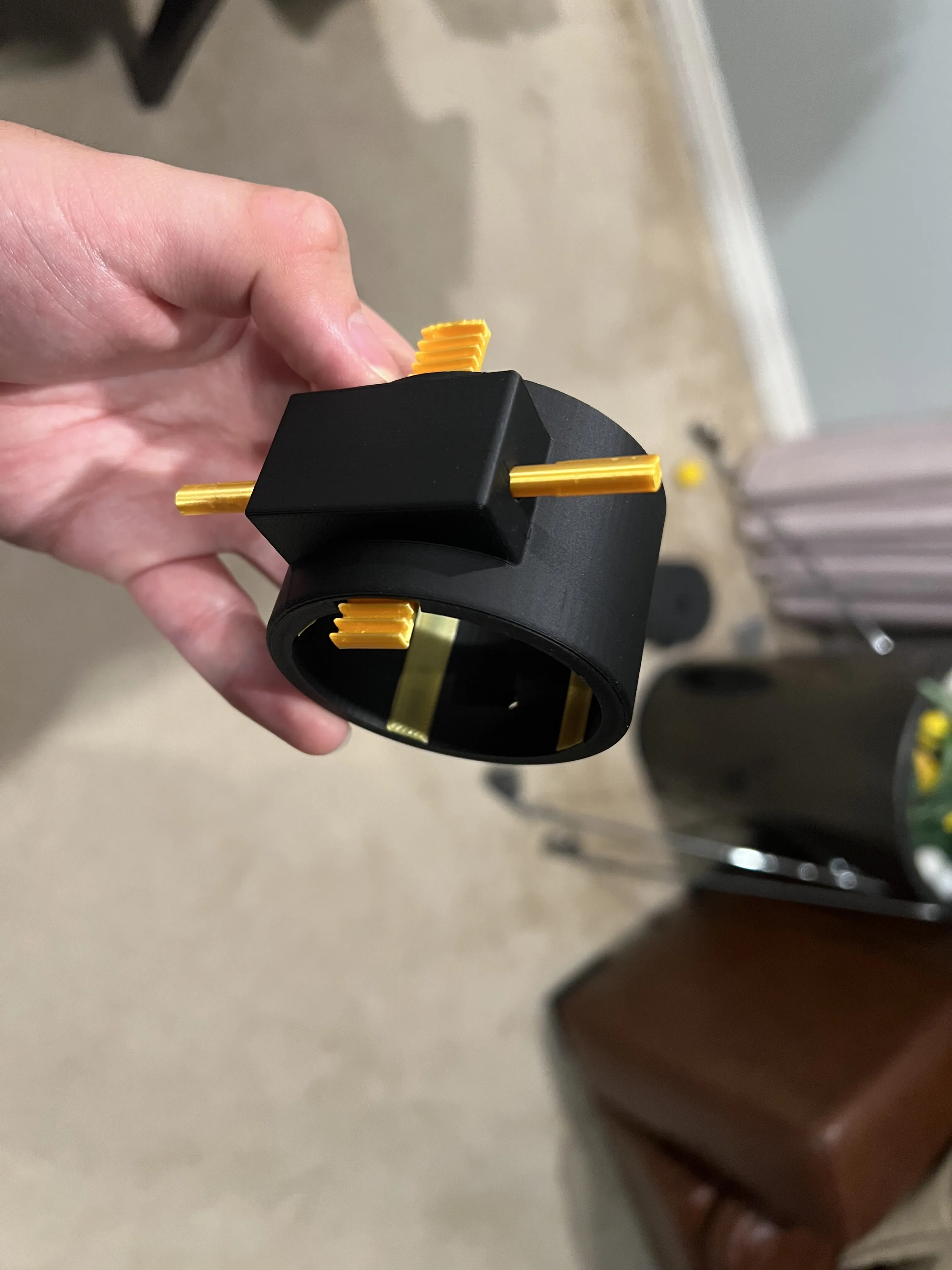
Congrats! The hard part is done. Now position the rack over the gear. Note how one side of the rack has a tooth that's taller than the rest. This prevents the tube from sliding out all the way. This end faces down (top of image).
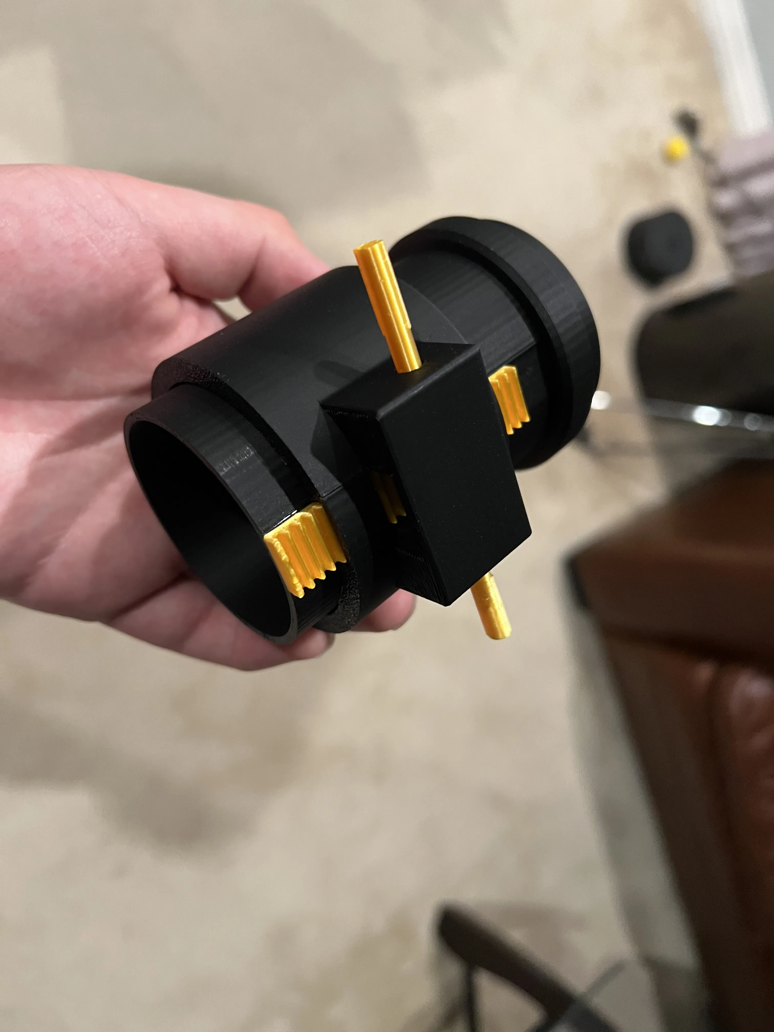
Apply glue, and slide the drawtube into the guide tube, carefully aligning with the rack. Press until secure.
The last steps are simple: slide the assembly into the base plate. For the compression rings, bend them slightly and push them into the notches in the drawtube and the 1.25" adapter.
License

You shall not share, sub-license, sell, rent, host, transfer, or distribute in any way the digital or 3D printed versions of this object, nor any other derivative work of this object in its digital or physical format (including - but not limited to - remixes of this object, and hosting on other digital platforms). The objects may not be used without permission in any way whatsoever in which you charge money, or collect fees.


Comment & Rating (0)