
Portable medieval torch
Print Profile(1)

Description
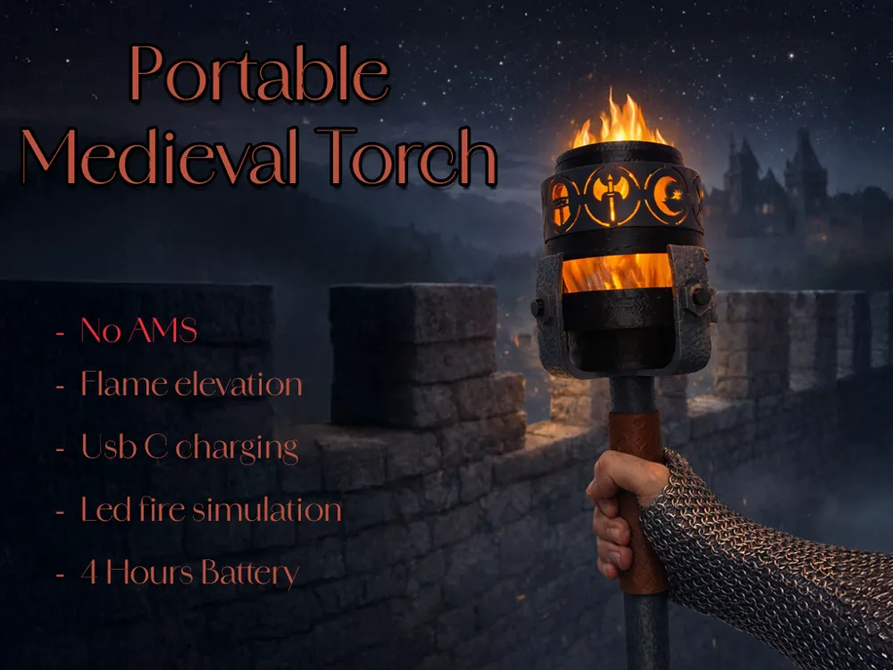

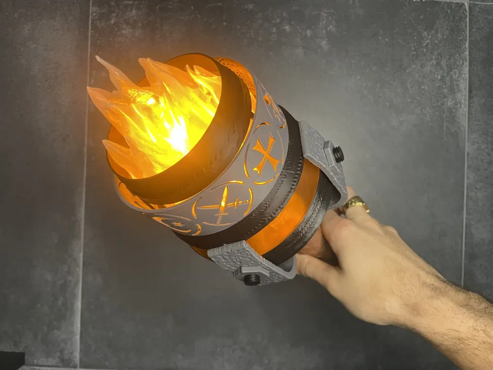
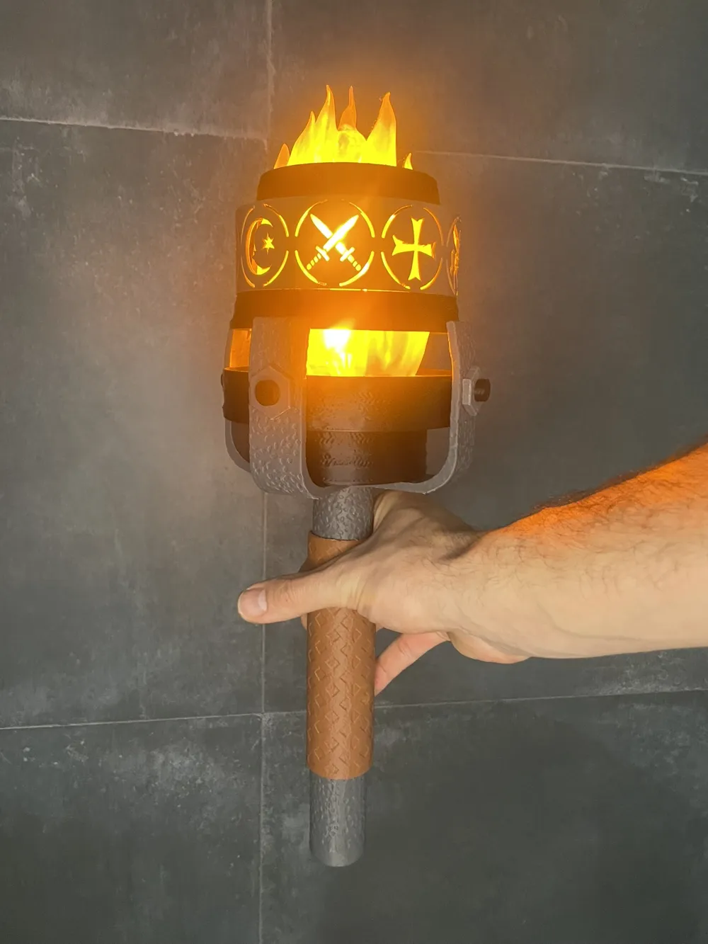
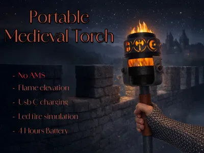
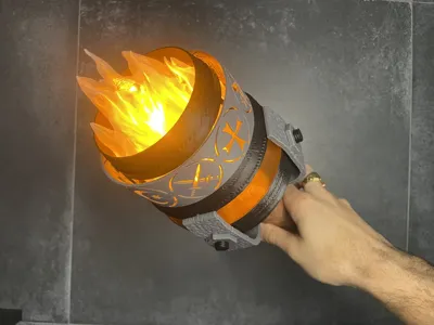
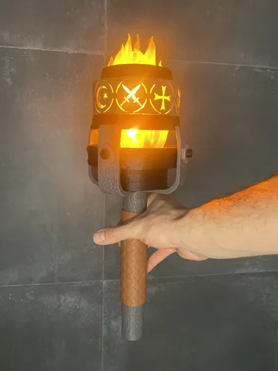
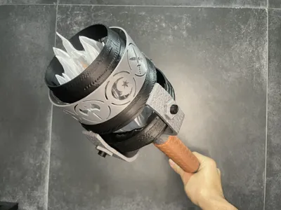

Portable Medieval Torch
I share this creation initially designed for playing with my son on night adventures! When not in use, it will serve to decorate a corner of the living room.
Boost Me (for free)
It's free! And it helps us continue creating free models!
About the Torch
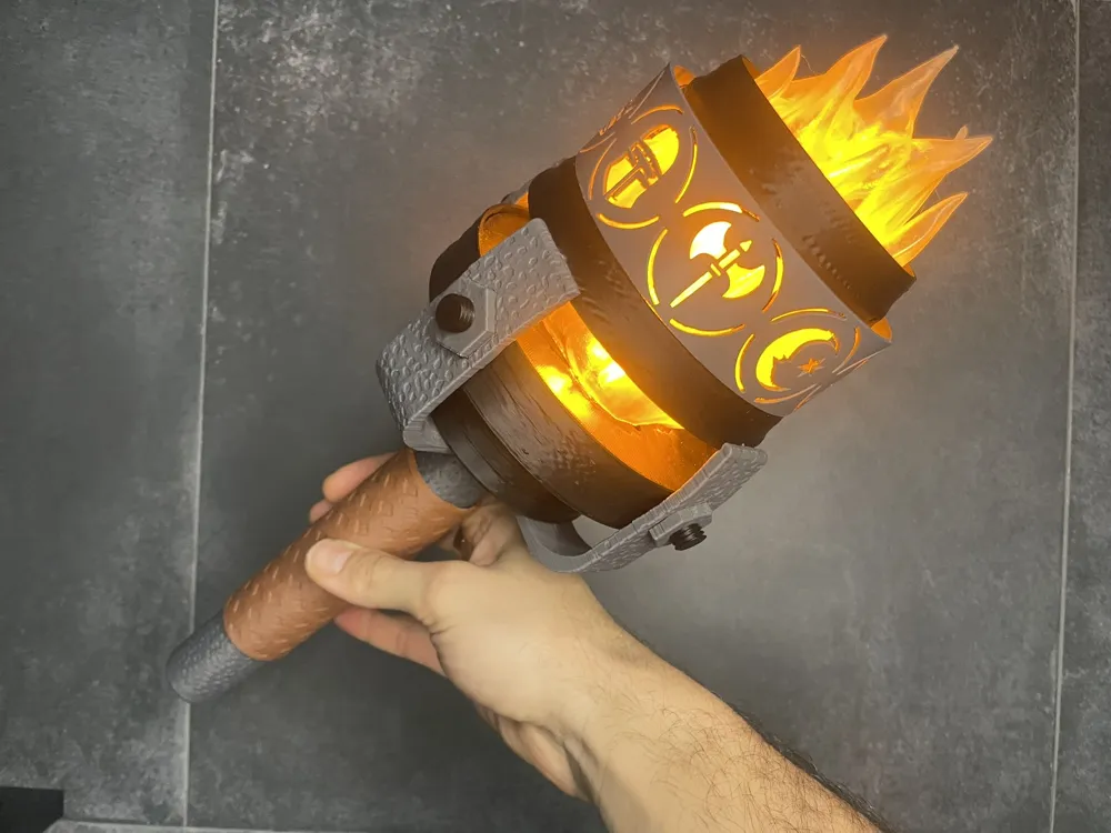
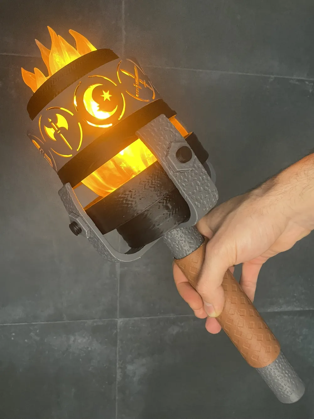
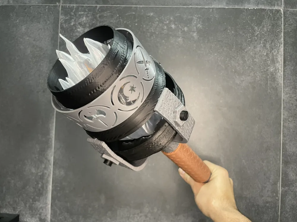
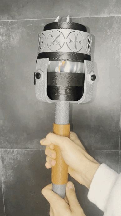
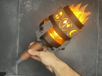
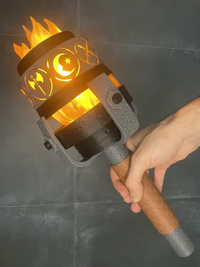
This is inspired by a medieval-type torch. It contains medieval symbols through which light passes, and a fire elevation mechanism that activates when lit. Both lighting the fire and raising it are done by moving the handle. To activate the mechanism, we just need to turn the "leather" handle, and it will move vertically to an upper point, then the flame will rise and light up.
Basic tin soldering knowledge is required for assembly as it includes a battery and LED components.
The type of LED used is a small module that simulates a real fire (flame). In our case, we used 3 LED modules for greater luminosity, with this configuration we have a battery life of + 4 hours.
The entire torch design, with the exception of the flame, is designed in Fusion 360.
Dimensions: Height 45cm x Width 15cm
Required
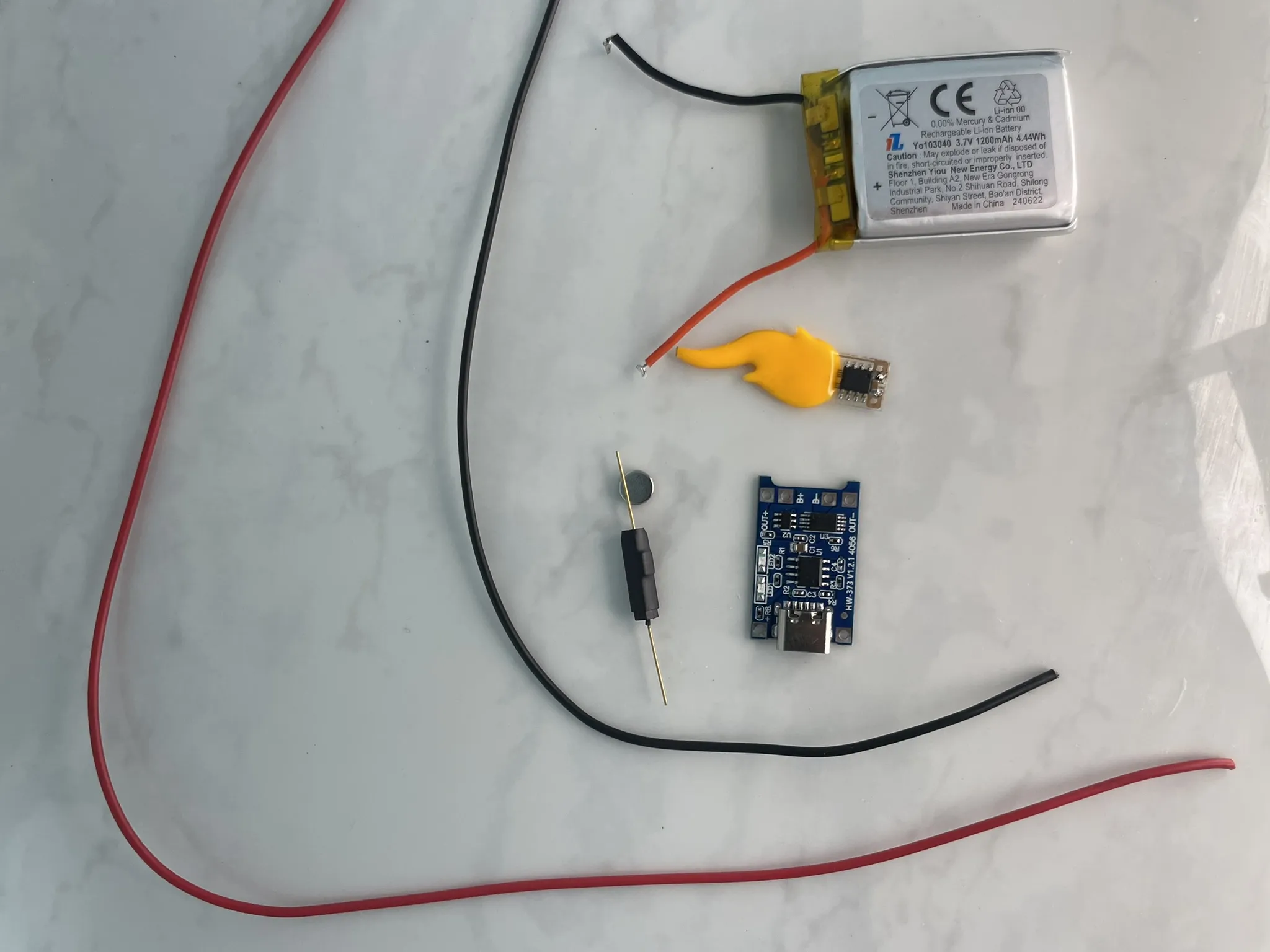
- Flame LED: https://es.aliexpress.com/item/1005009986565382.html?spm=a2g0o.order_list.order_list_main.5.6f23194dJLDZcv&gatewayAdapt=glo2esp
- Magnetic switch: https://www.amazon.es/dp/B088CQL44X?ref=ppx_yo2ov_dt_b_fed_asin_title
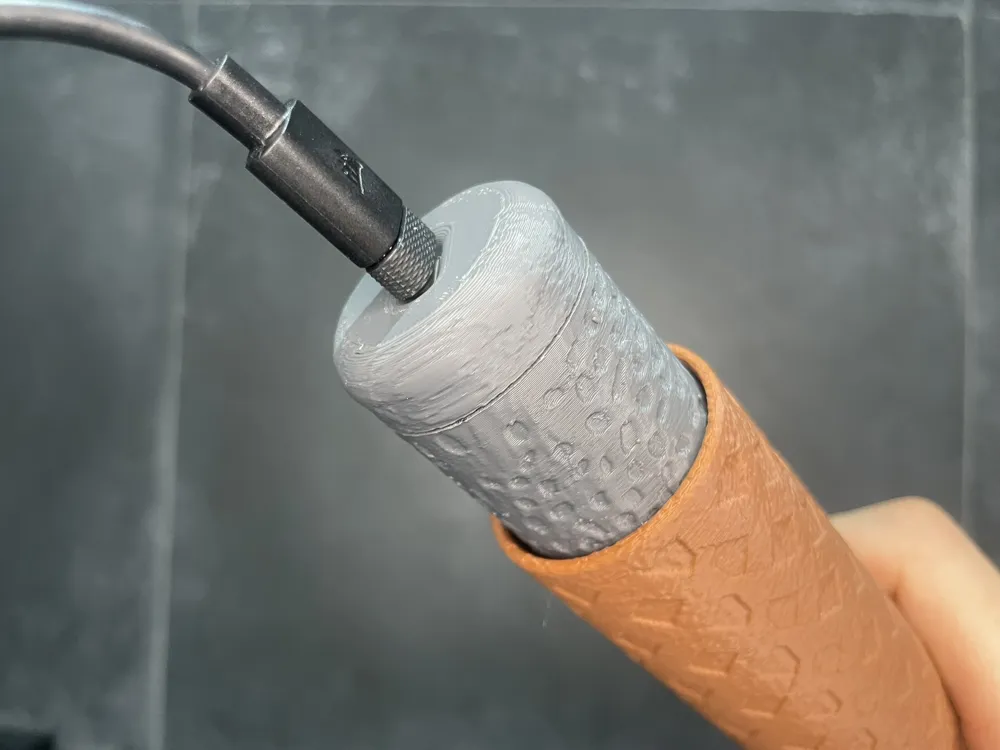
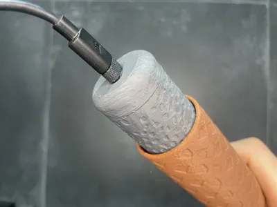
- TC4056 battery charging module: https://www.amazon.es/dp/B0BZSB3SBN?ref=ppx_yo2ov_dt_b_fed_asin_title&th=1
- 103040 battery: https://es.aliexpress.com/item/1005006864773152.html?spm=a2g0o.productlist.main.1.19ferpLYrpLYv8&algo_pvid=d7c2fa84-3f8d-4d77-91fc-d49b8ed67861&algo_exp_id=d7c2fa84-3f8d-4d77-91fc-d49b8ed67861-0&pdp_ext_f=%7B%22order%22%3A%22485%22%2C%22spu_best_type%22%3A%22price%22%2C%22eval%22%3A%221%22%2C%22fromPage%22%3A%22search%22%7D&pdp_npi=6%40dis%21EUR%218.07%215.49%21%21%2164.61%2143.95%21%40210390c217675281439315810e0f40%2112000038555430962%21sea%21ES%211873488058%21X%211%210%21n_tag%3A-29919%3Bd%3Afeb7669e%3Bm03_new_user%3A-29895&curPageLogUid=xEjxIr5jLxgO&utparam-url=scene%3Asearch%7Cquery_from%3A%7Cx_object_id%3A1005006864773152%7C_p_origin_prod%3A
- Glue: Any cyanoacrylate glue.
- Cables: You can use AWG16 or AWG18 cable, both would work.
Assembly
It is very important to follow each step of the assembly process. Especially the step of adjusting the magnetic switch.
Once all the pieces are printed, we will assemble everything without glue to check that the printing has been done correctly and all the elements fit together.
Upper Rings
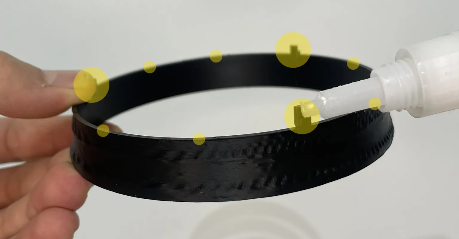
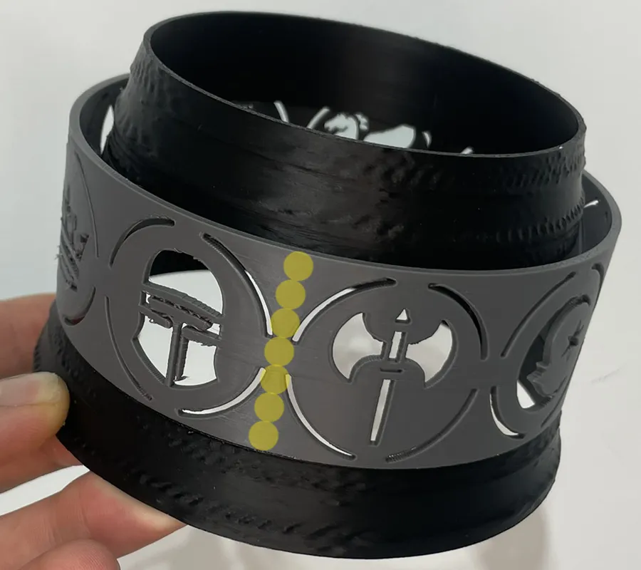
Apply one drop in each of the 3 recesses of the lower ring, 6 smaller drops along the ring, and place the 2 upper pieces. Match the symbol change with one of the lower recesses.
Handle
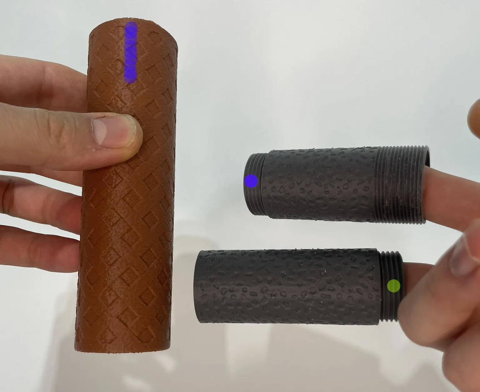
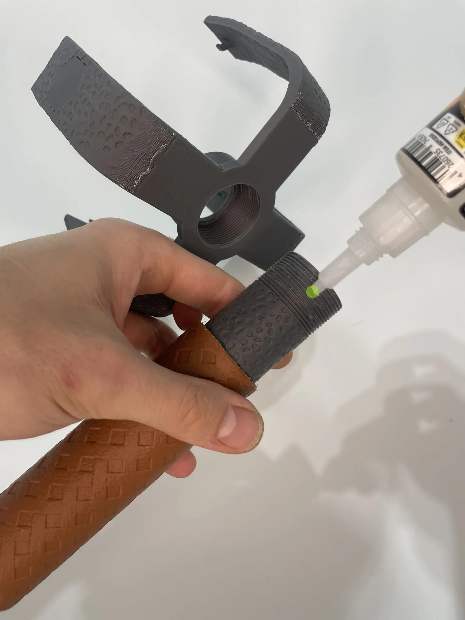
The upper part of the handle is where the lifting rod is located. Apply a drop of glue and screw it in all the way.
Scoops
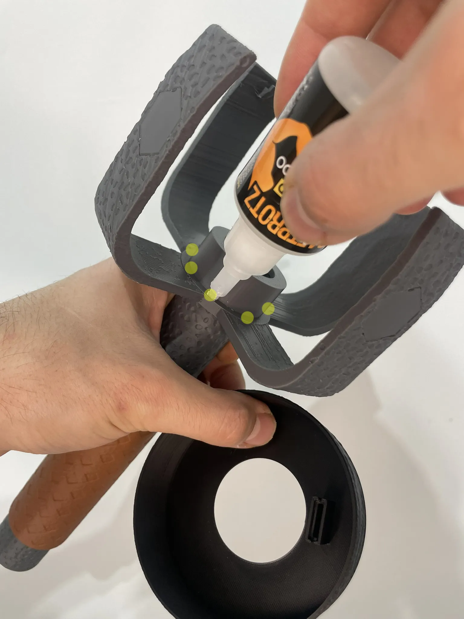
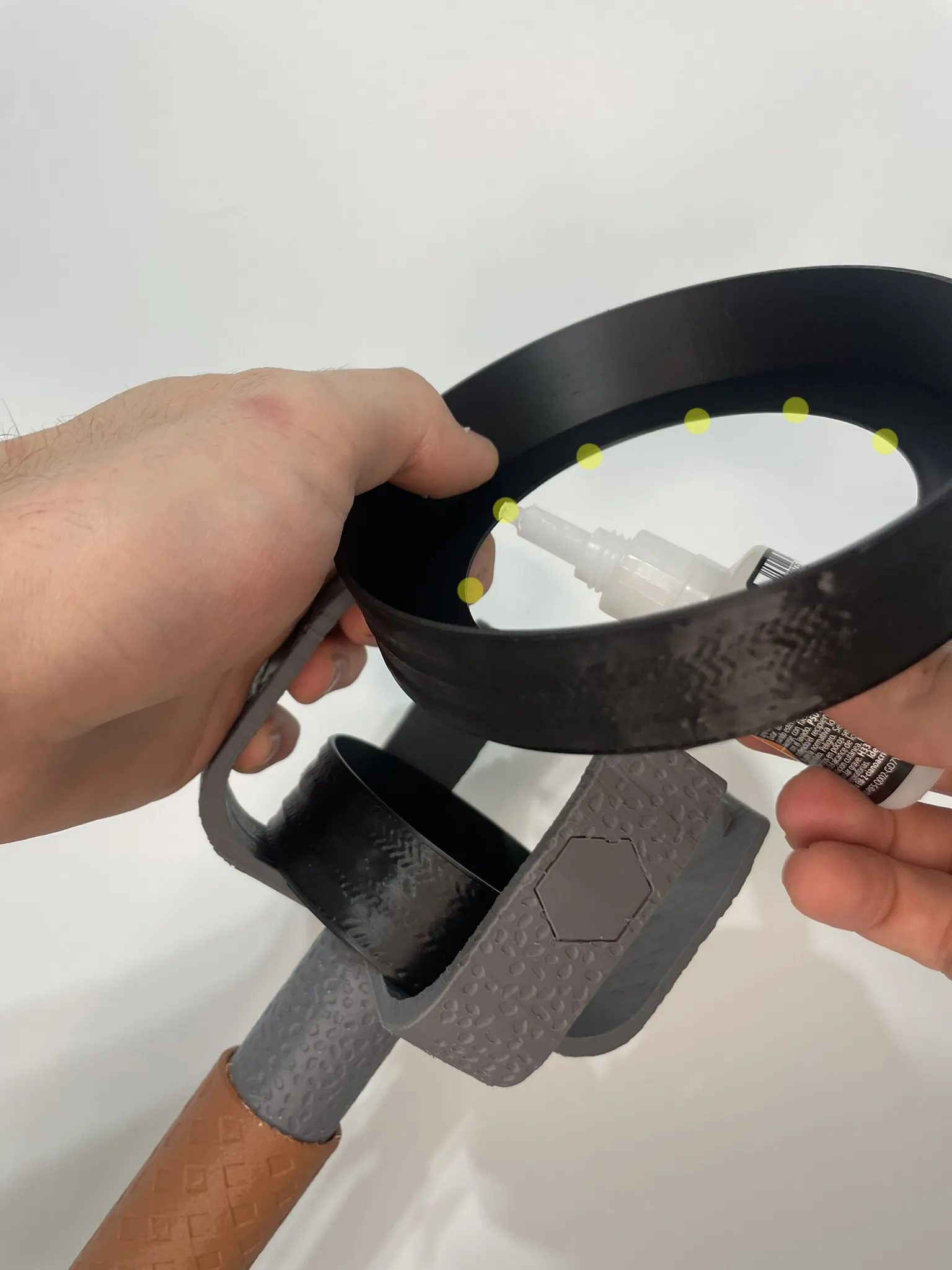
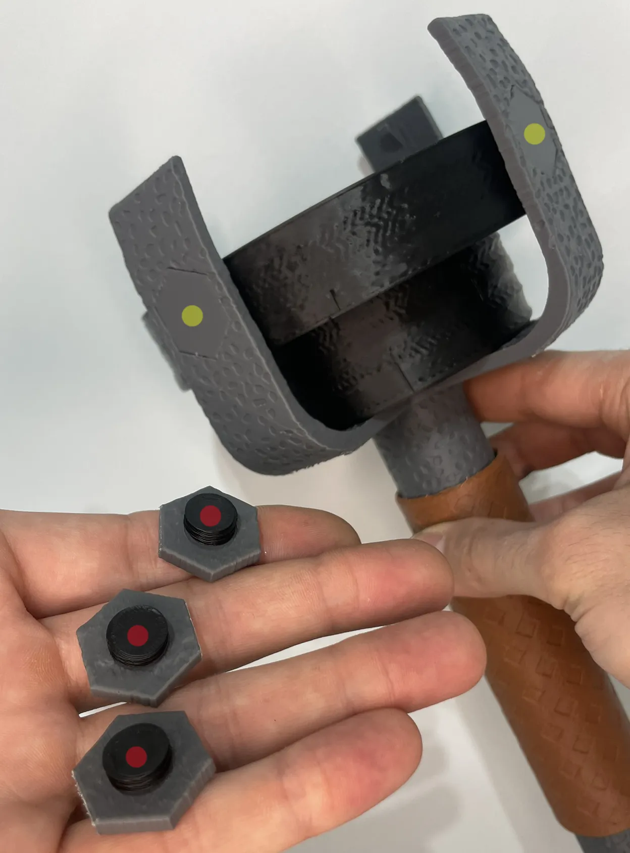
Apply a few drops around the parts marked in yellow. The position does not matter.
Screws
Apply a drop of glue to join the threads and nuts. Then add a drop at each point of the claw and let it dry.
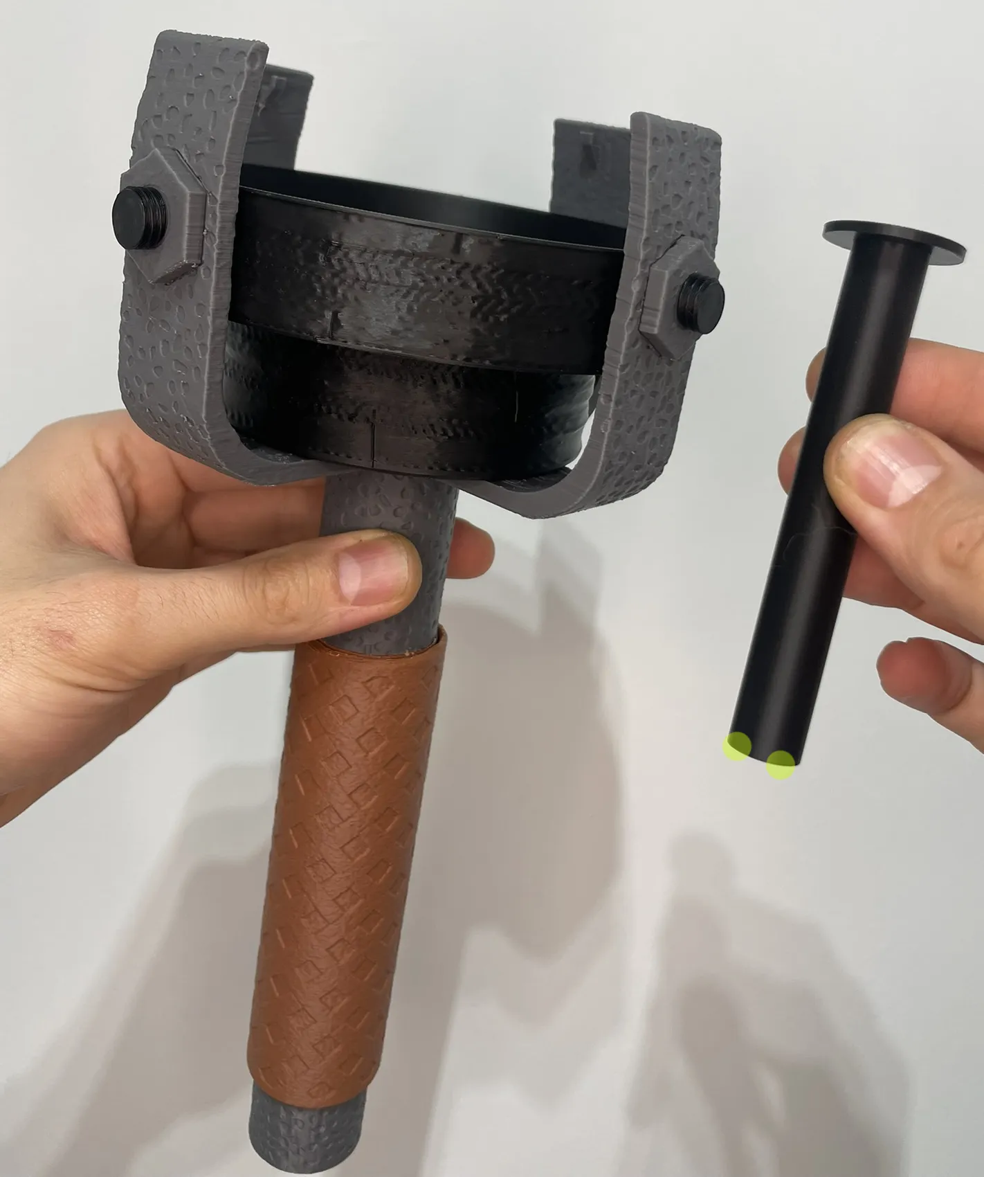
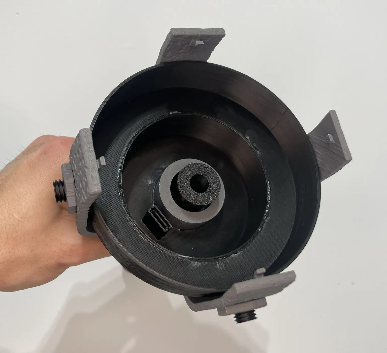
Lifting Rod
Apply glue to the bottom and inside of the rod and insert it.
Electrical Part
Part 1 Charging system and switch
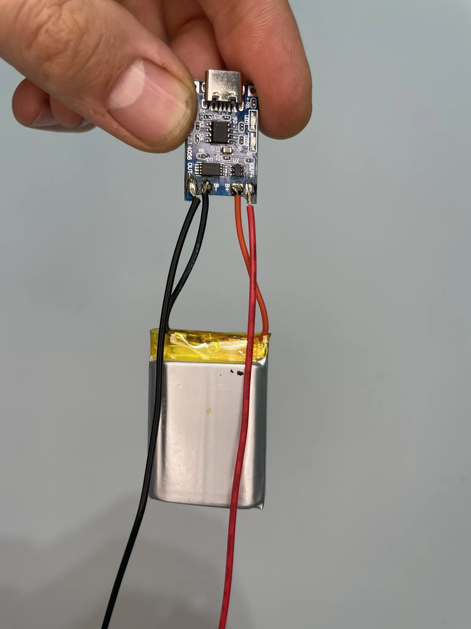
- Solder the black battery cable to pin B- and the red cable to pin B+ (approx. 5cm cable).
- Solder a 40cm black cable to pin OUT- and a 40cm red cable to pin OUT+.
- Solder the magnetic switch to the end of the black cable and continue with a 20cm black cable.
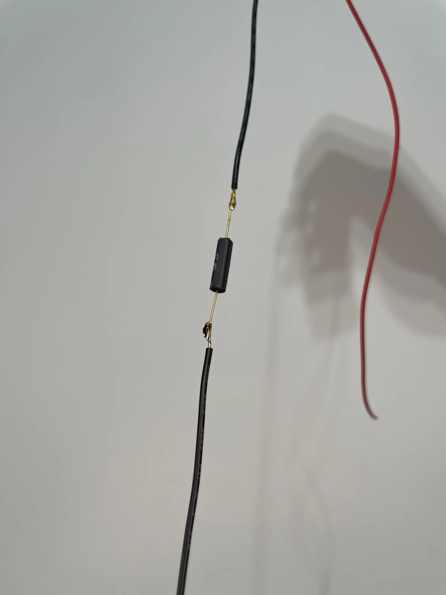
Part 2 LED Module
- Solder a black cable to the - pin and a red cable to the + pin of each of the three LED modules. Each module has cables of different lengths: 6 cm, 9 cm, and 12 cm.
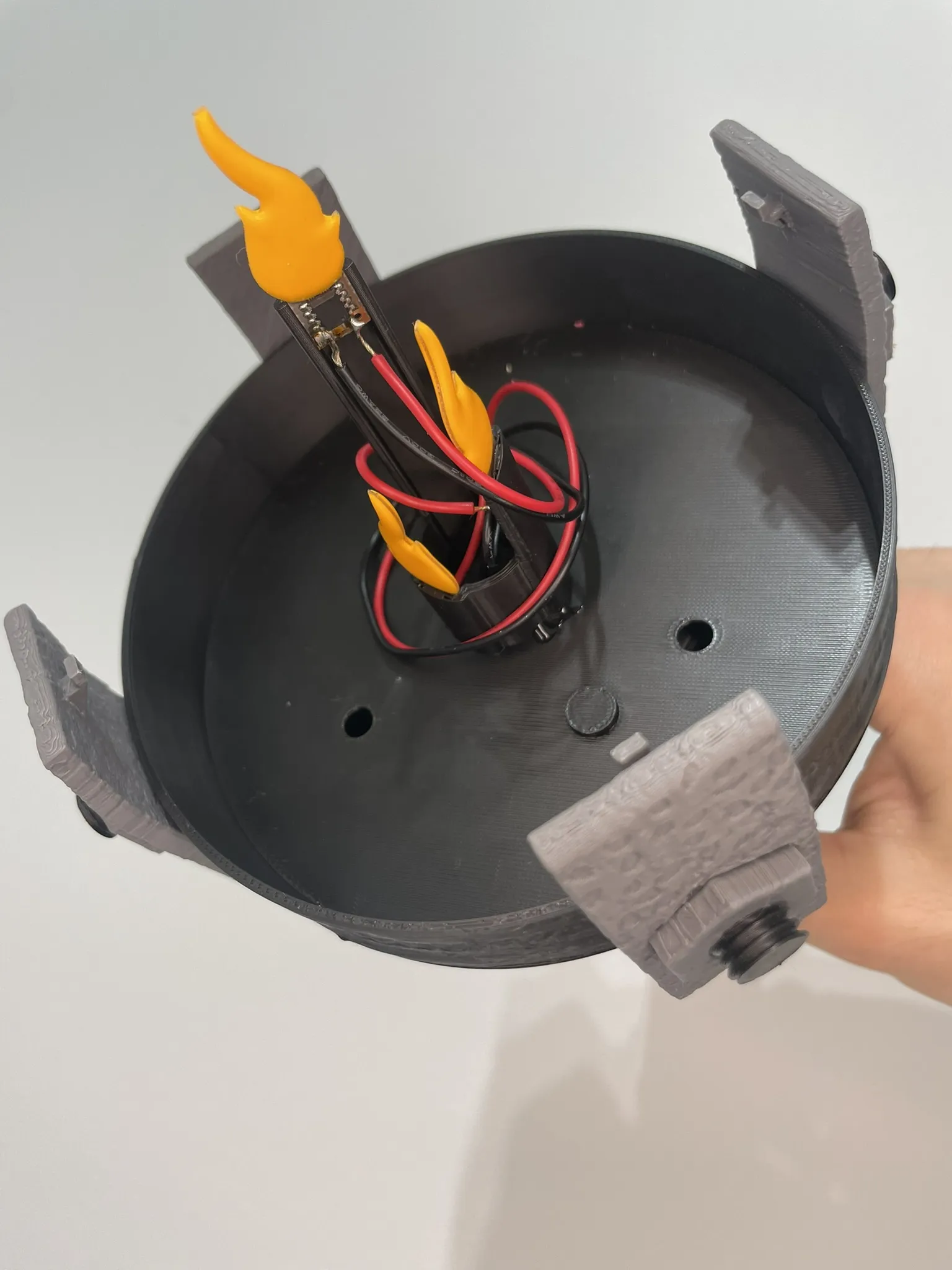
- Place the modules on the platform and solder the cables of the same color.
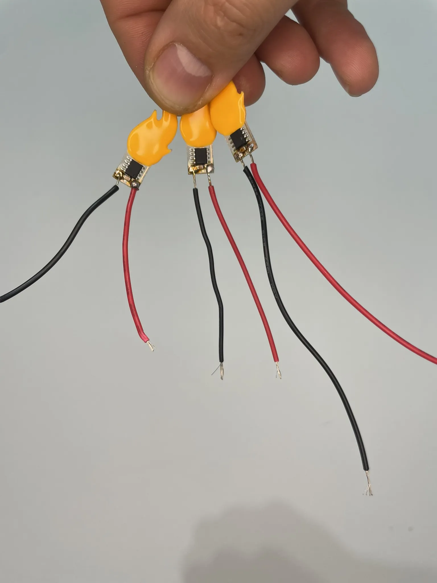
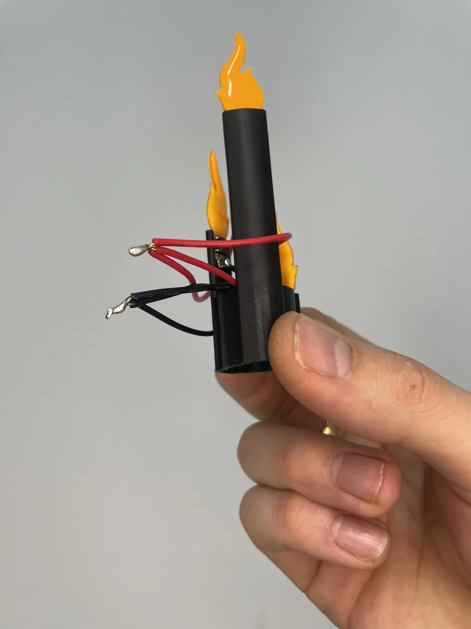
Part 3 Magnetic Switch
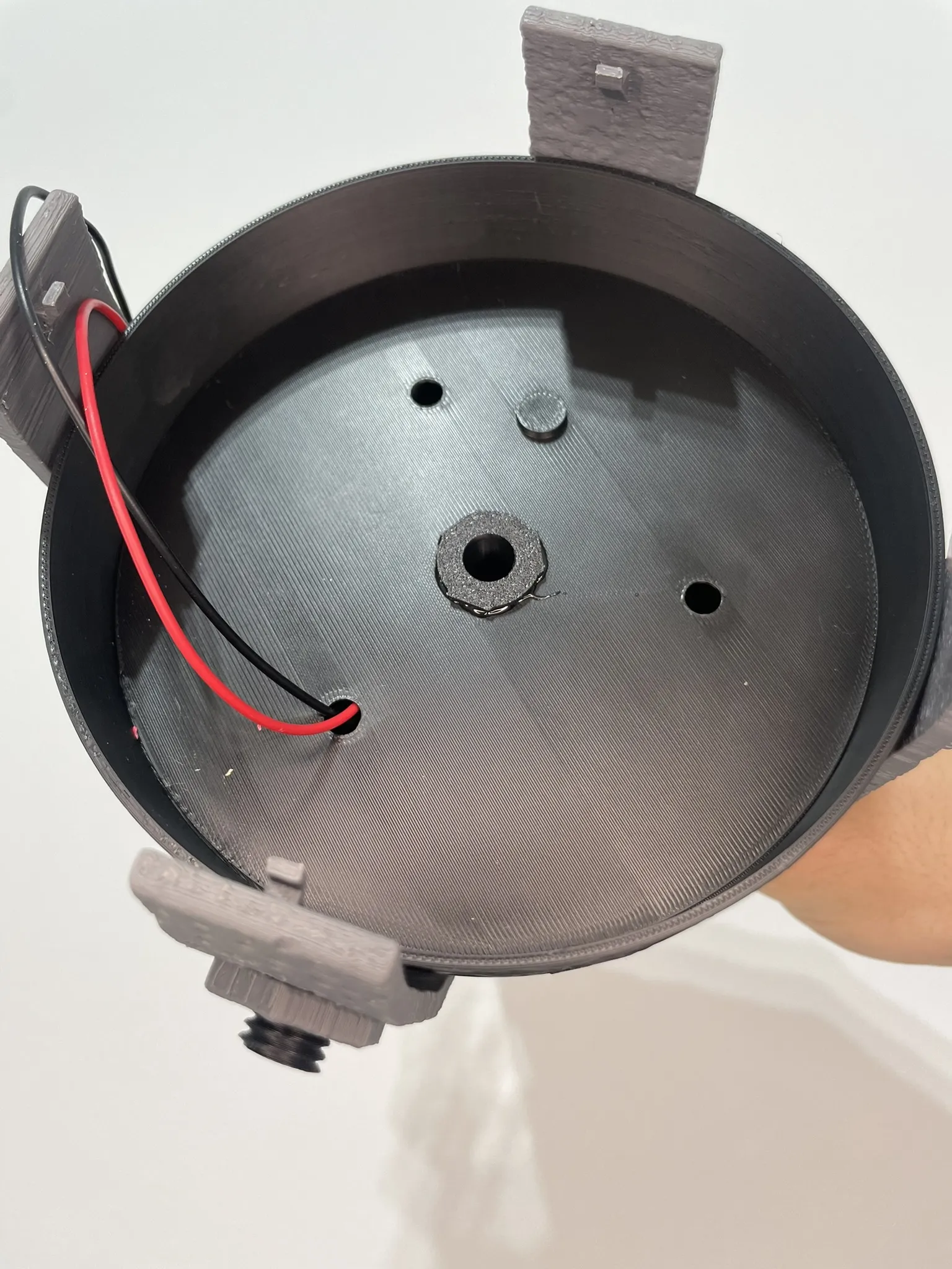
- Insert the soldered cables through the bottom of the torch until the magnetic switch is at the top.
- Place the magnetic switch in its housing in the position shown in the photograph.
- VERY IMPORTANT Place the torch handle in the lowest locked position. On the lifting rod, mark with Tippex indicating the position of the magnetic switch; this will help us determine the position where the activation magnet will be.
- Place the 6mm magnet at the base of the platform.
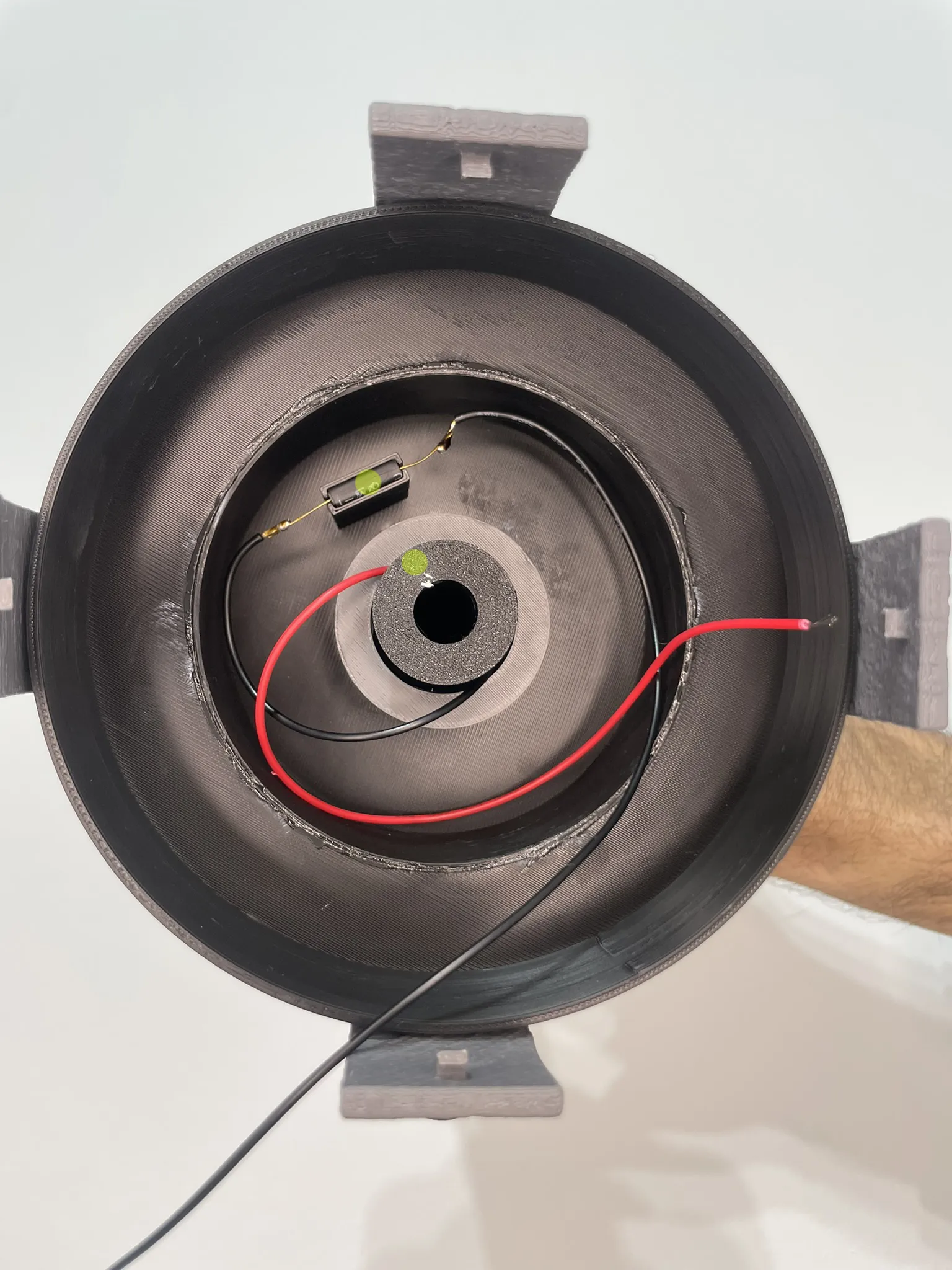
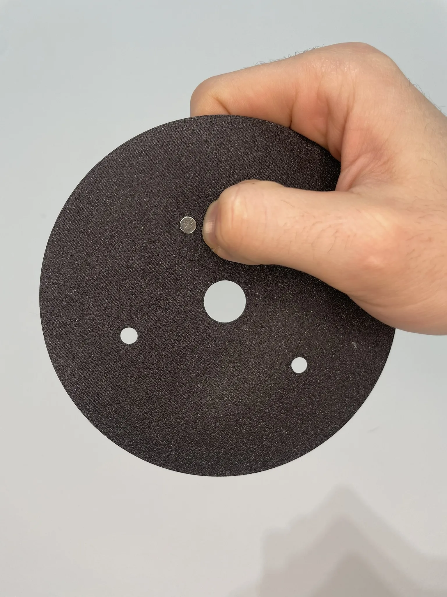
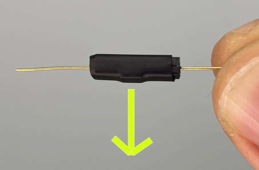
Part 4 Magnetic sensor connection and adjustment (VERY IMPORTANT: FOLLOW ALL STEPS)
- Keep the handle in the lowest locked position throughout the process. Check the position at all times for precise switch adjustment.
- Insert the cables through the most convenient hole, leaving a bit of cable inside. The mark we previously made on the base of the platform will help us find the closest position of the magnet and the switch.
- Solder the cables to the LED module assembly. At this point, the LEDs might light up. Remove them from the torch to proceed with the next step.
- VERY IMPORTANT This is when we will find the position of the magnet relative to the switch. Check the handle's position, which must be in the lower lock, and do not change its position until we glue the base. If the LEDs are on, we must turn the base until they turn off. If the LEDs are off, check that they light up when turning the base.
- When the LEDs are off and the handle is in the lowest locked position, apply glue to the connecting piece and place it to join the rod to our base. Let it dry thoroughly.
- Add the LED module tower to the connecting piece.
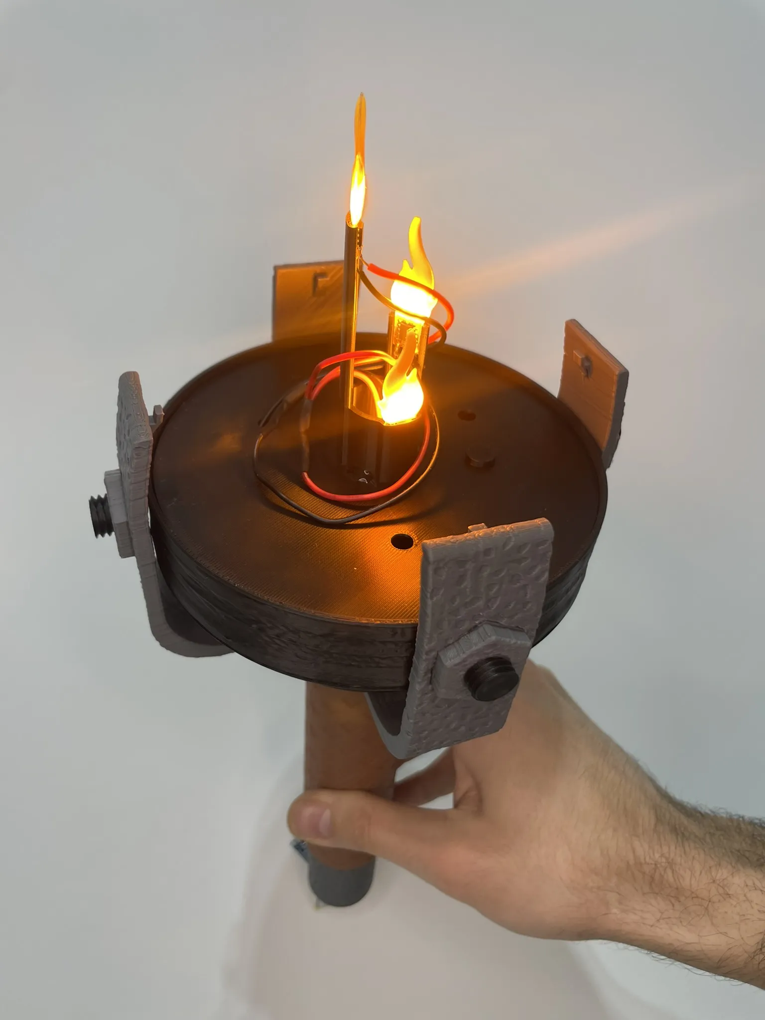
- The magic happened: WE TURN, WE LIFT, AND WE LOCK. WE HAVE FIRE!!!!
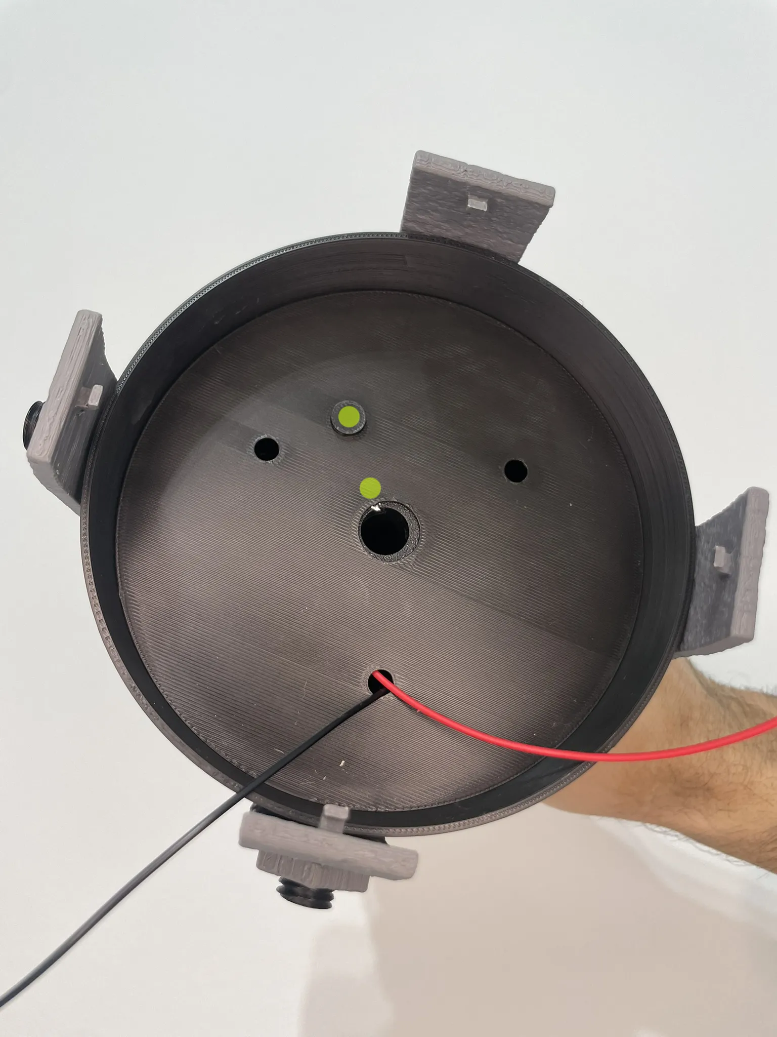
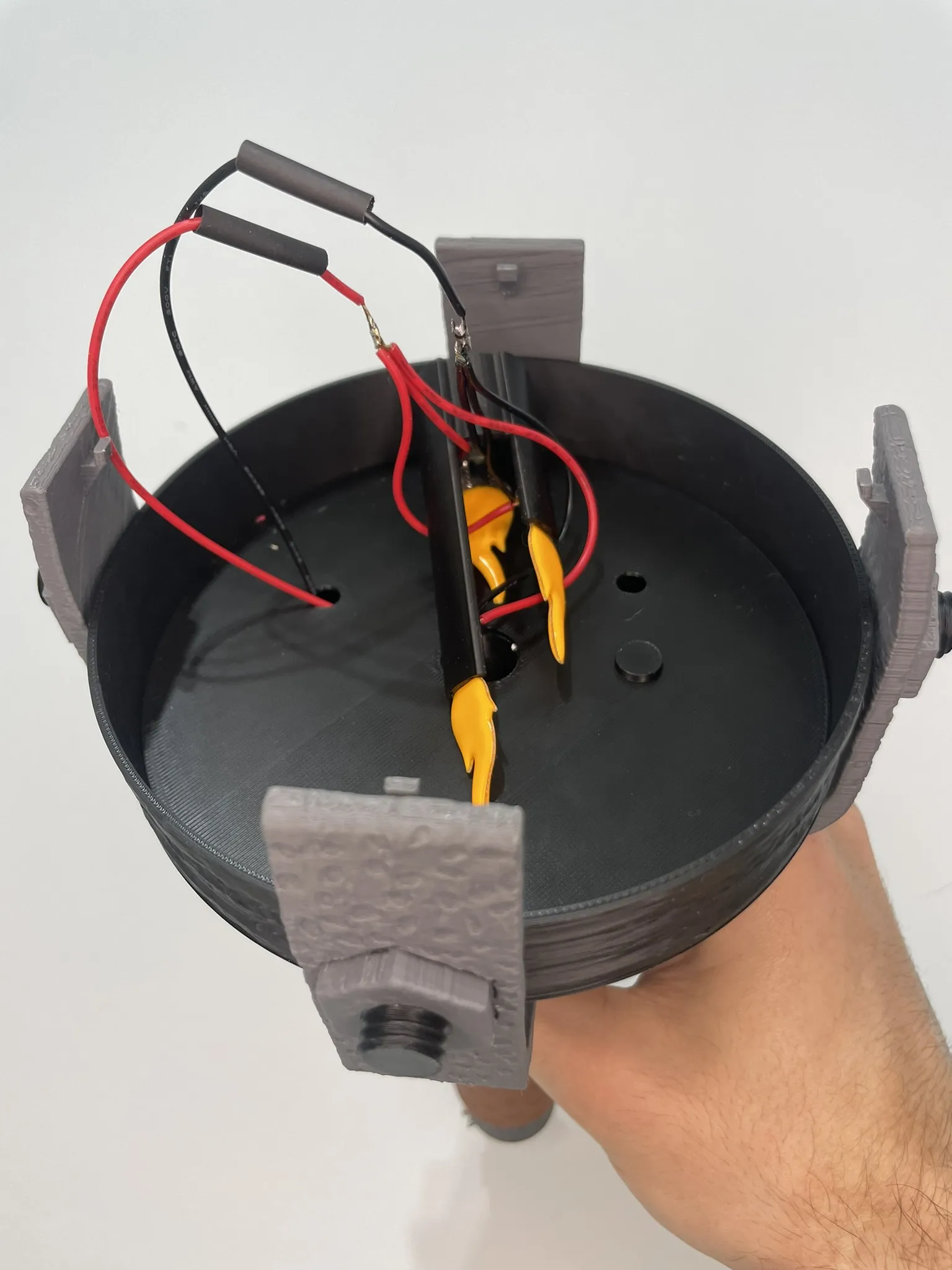
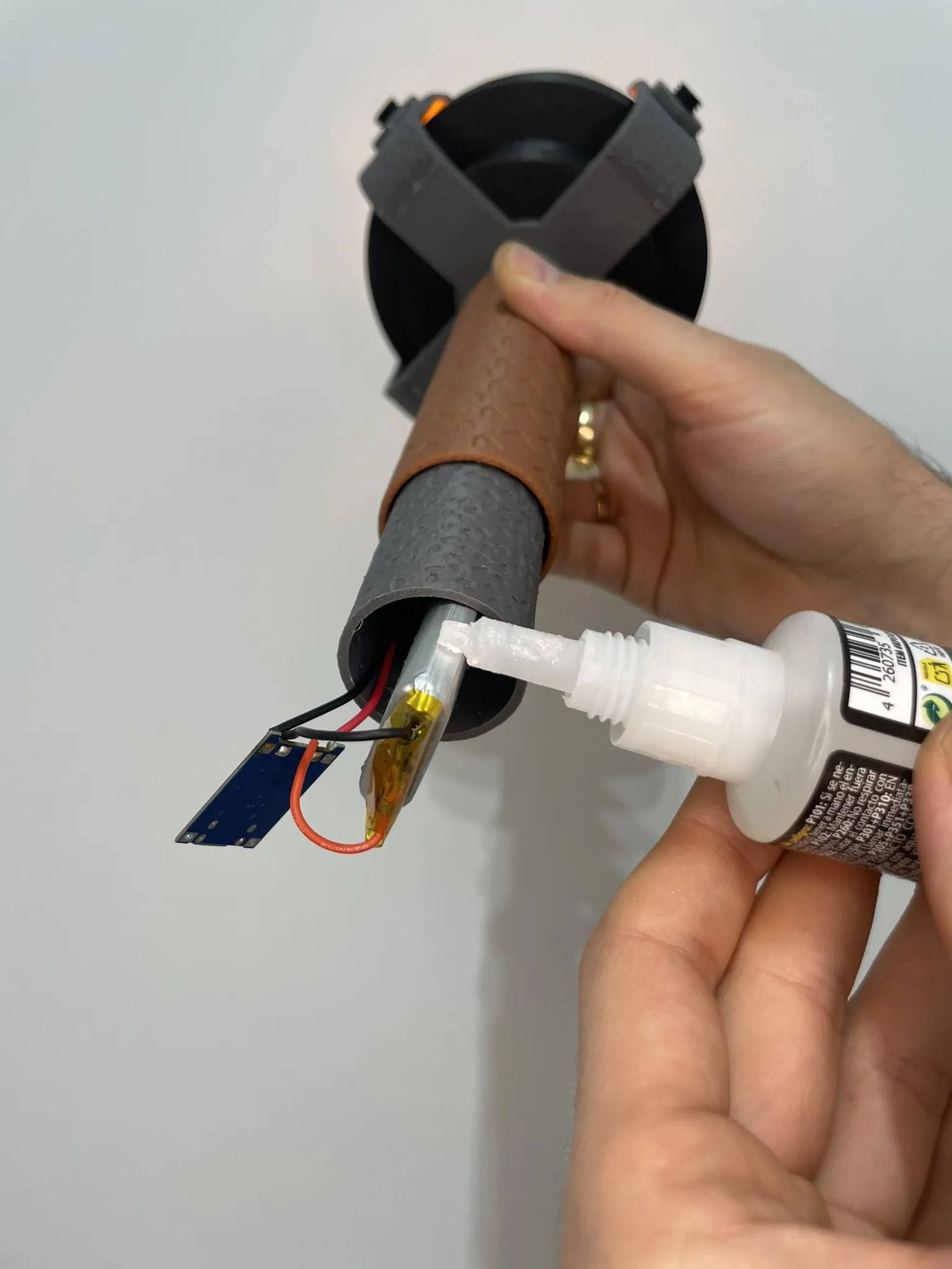
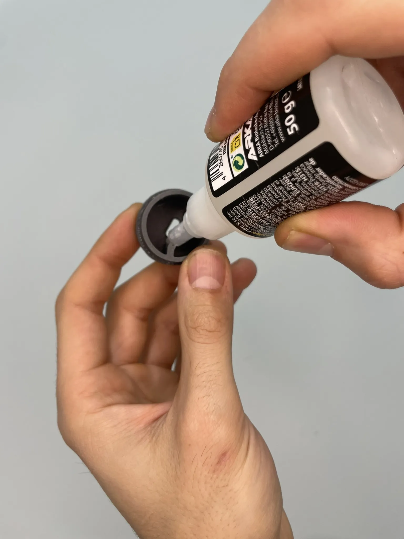
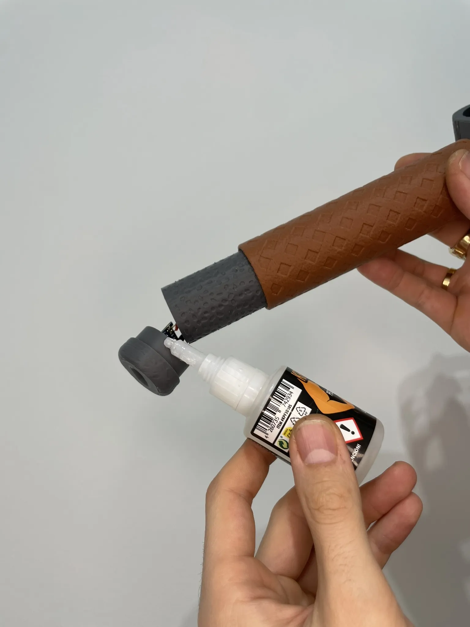
TC4056 Cap Holder
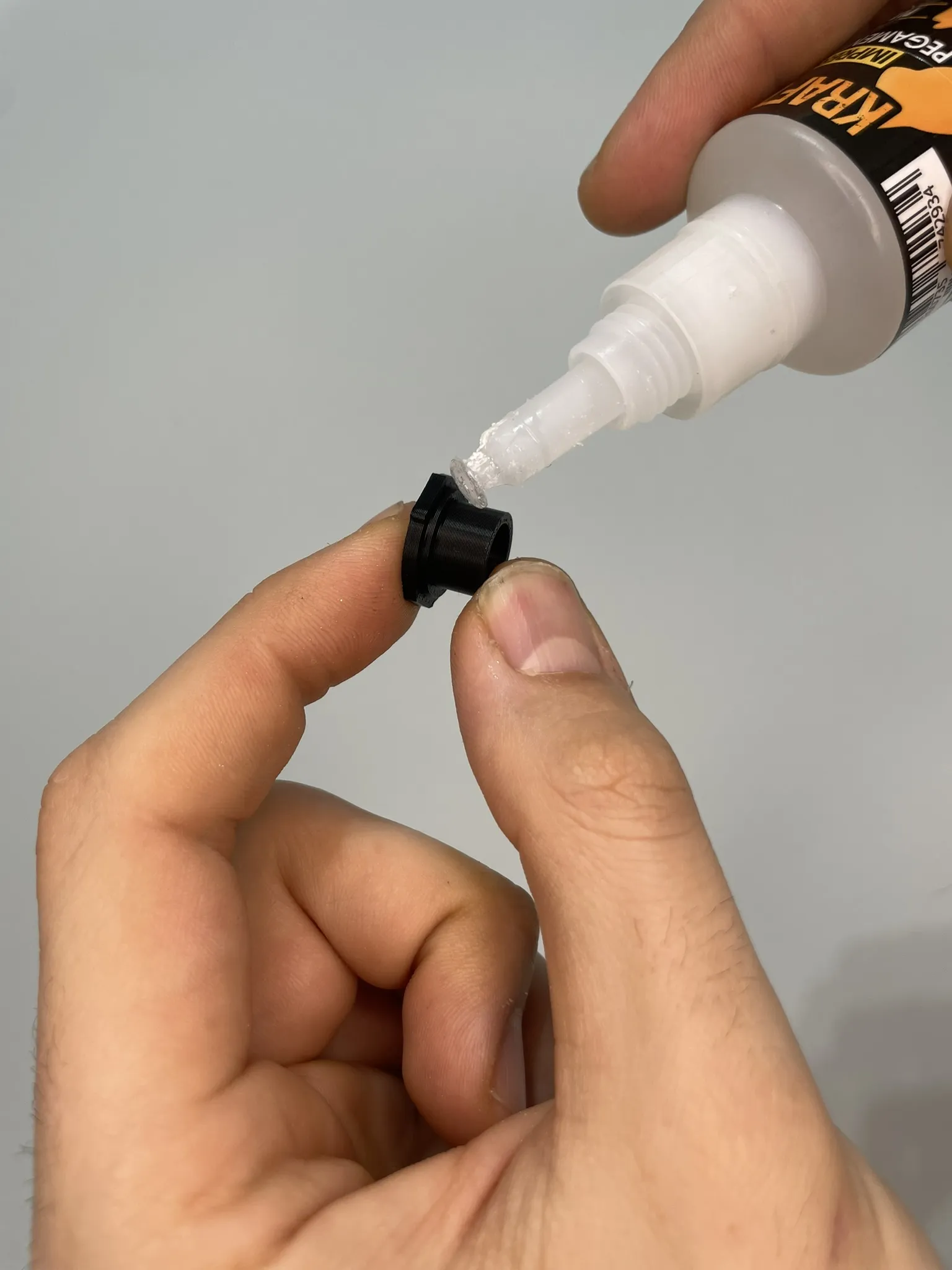
Apply a drop on the edge of the battery, two at the end of the cap rail, on the cap itself, and assemble.
Flame and Upper Rings
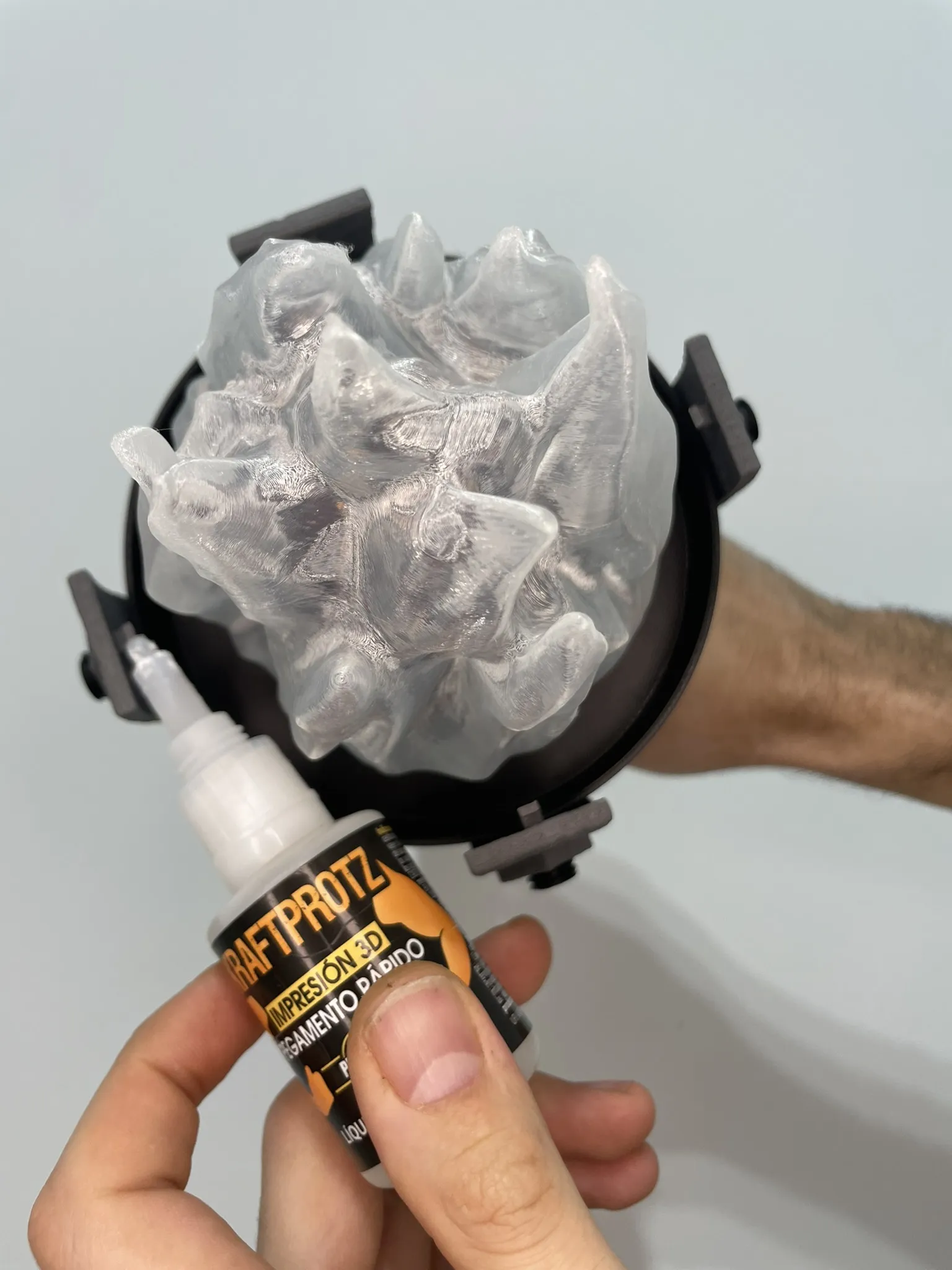
- Place the flame without gluing it.
- Apply glue to the 4 supports and place the rings.
- Rotate the handle and raise the flame to its highest position.
- From a top view, check the flame's position and ensure it does not touch any upper ring.
- Hold the flame and apply 4 drops of glue around the flame.
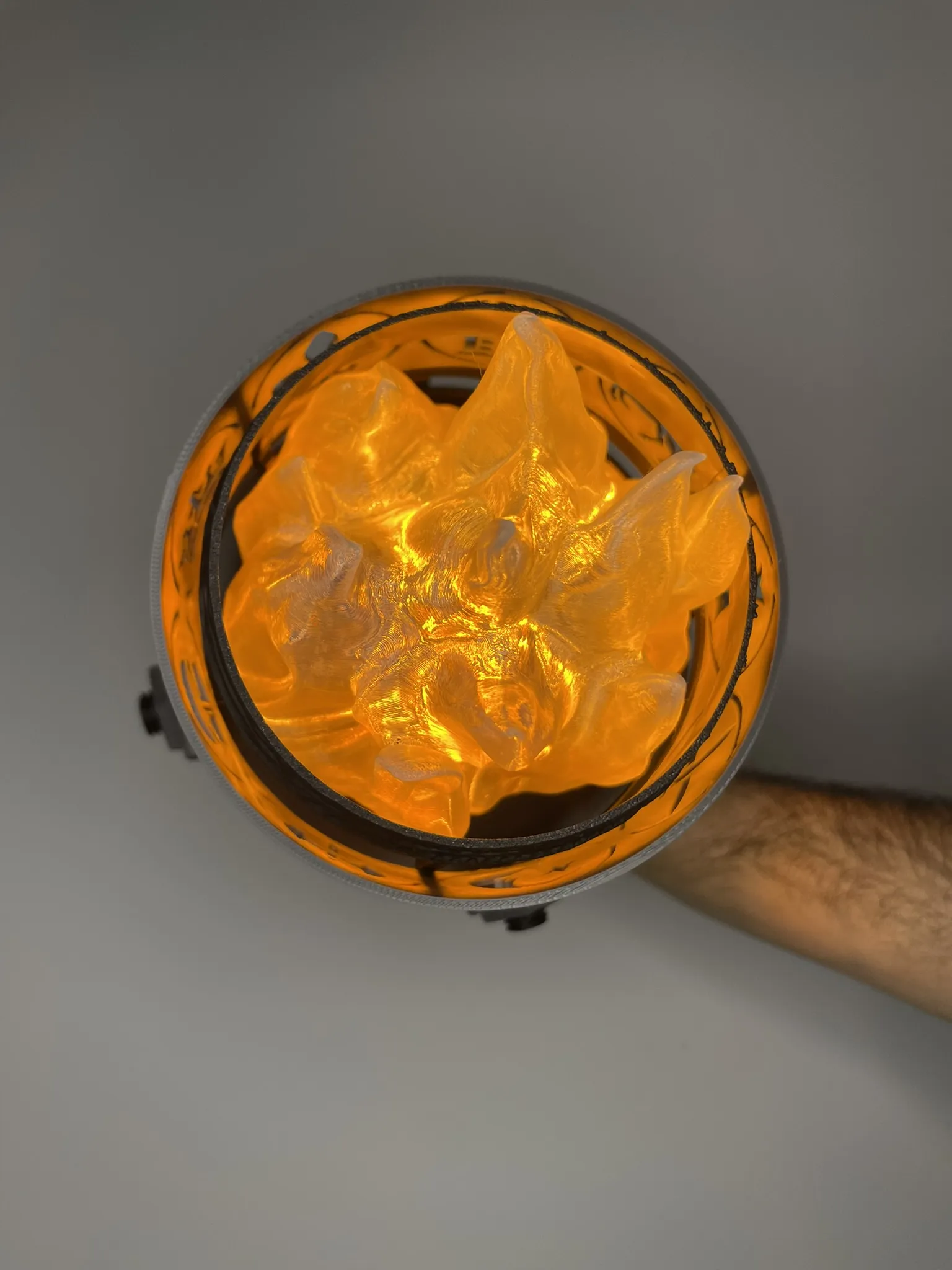
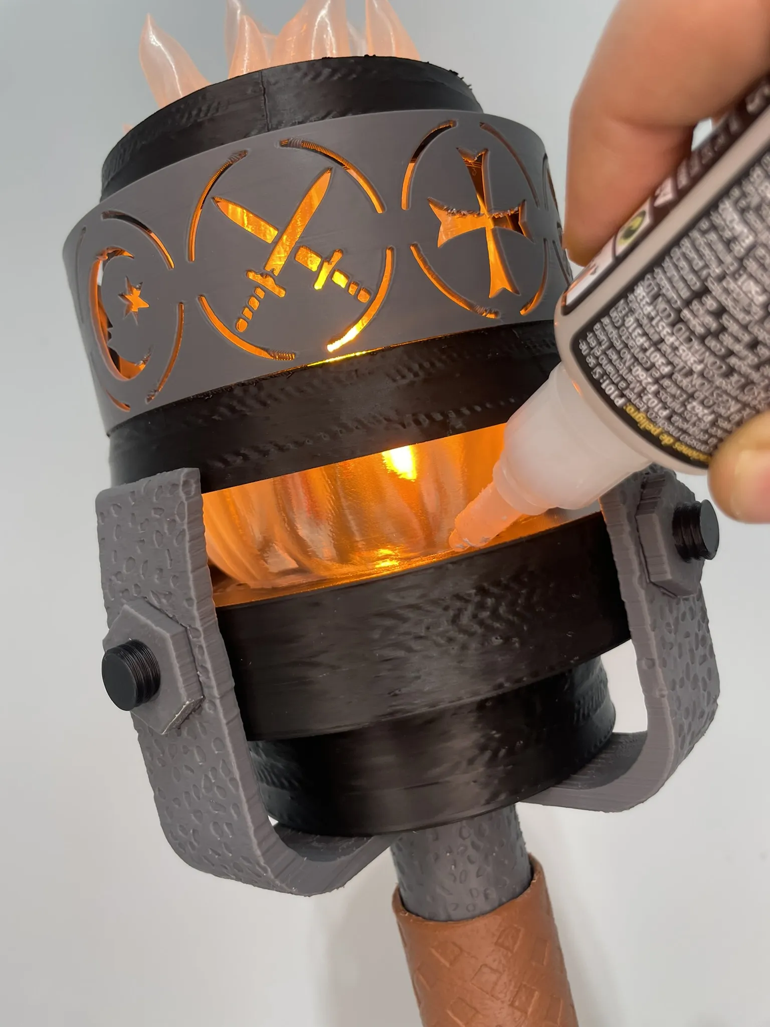
TORCH COMPLETED
License

You shall not share, sub-license, sell, rent, host, transfer, or distribute in any way the digital or 3D printed versions of this object, nor any other derivative work of this object in its digital or physical format (including - but not limited to - remixes of this object, and hosting on other digital platforms). The objects may not be used without permission in any way whatsoever in which you charge money, or collect fees.


Comment & Rating (0)