


Print Profile(2)

Bill of Materials


- LED 3V COB Flexible Filament 300mm x 1: Blue, red and orange (I used warm white)
- Resistors x 1: 1x 10 Ohm, 2x 33 Ohm
- Micros Switch x 2: Optional to disable screen and cam
- UV Resin (and UV lamp) x 1: Optional to give laser cube a shiny glass like look
- Cheap Yellow Display (ESP32-2432S028) x 2:
- ESP32-CAM with camera x 2:
- ESP32-CAM downloader modul x 1: Used to flash ESP32-CAM
- Electrolytic capacitor x 1: 2x 1000uF, 4x 100 uF, 1x 470uF
- Ceramic capacitor x 1: 4x 100nF
- Cable x 1:
- USB C port or similar x 2: Used to provide power
- Heat shring tubing x 1: To prevent light bleeding and to prevent short circuit
- M3 screws x 1: 4x 6mm, 4x 10mm, 6x 12mm
- Duct tape (or similar) x 1:
- Clear translucent PLA x 1:
- Glue x 1:
Description
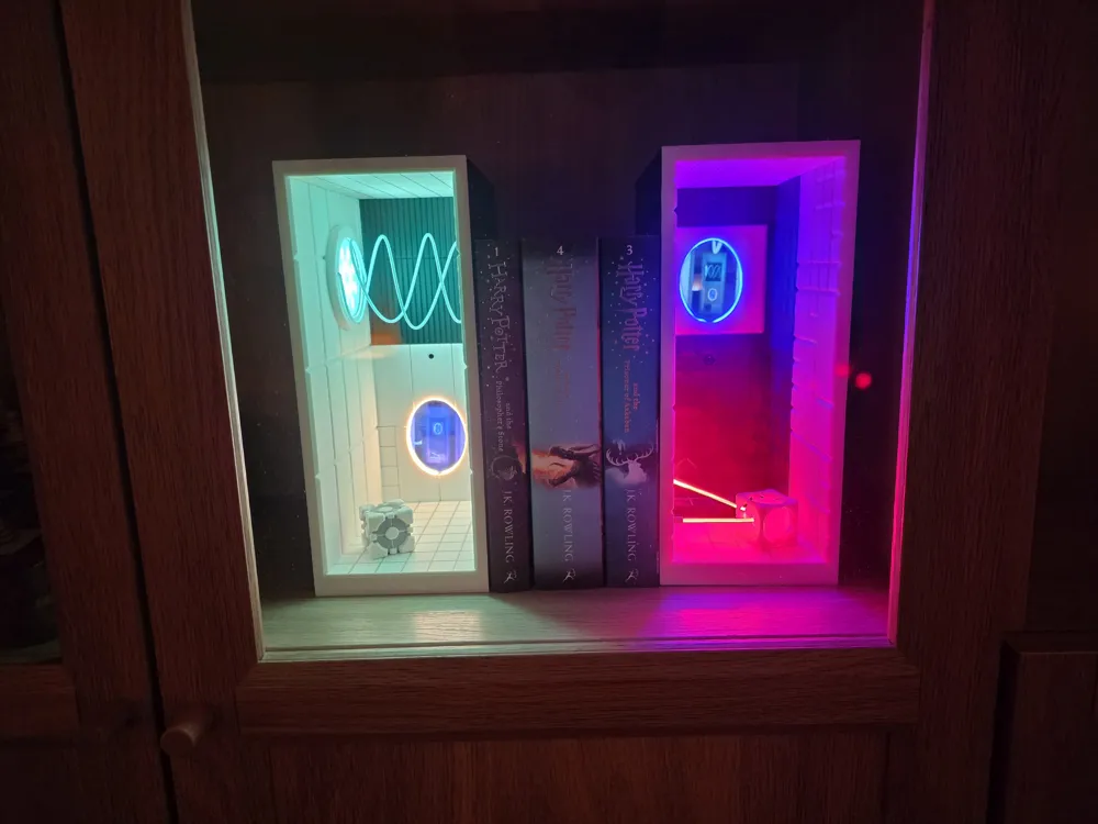
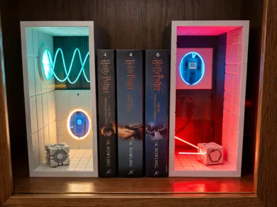
The cake is a lie? Maybe, but the portals can become reality! Bring these two book nooks into your bookshelf and watch the portals come to life with the help of screens and cameras.
Assembling the original high-tech version requires some technical skill (fine soldering, flashing an ESP32, etc.) and may not be ideal for beginners. That’s why additional components were designed to support two simpler versions: low-tech (regular soldering) and no-tech (no soldering). These are easier to build and more affordable.
The instructions are largely the same for all versions. Whenever the steps differ, the relevant variant is indicated.
Boost Me (for free)
Help me continue creating fun and practical models by boosting me – thank you!
Print plates
High-tech: All plates except the last two.
Low-tech: High-tech + last plate.
No-tech: High-tech + second-to-last plate.
Required tools
- Soldering iron or station (not for no-tech)
- Side cutters (not for no-tech)
- Small clamps (not for no-tech)
- Screwdriver
All required materials are listed in the Bill of Materials.
High-Tech Preparation
Flash the ESP32 boards using the provided sketches (ZIP archive). Label each board with a pen so you’ll know which controller belongs to which book nook.
Helpful setup guide for the display: ESP32-Cheap-Yellow-Display Setup
Orange Portal Build Guide

Step 1
Glue in the backplate as well as the top and bottom plates.

Step 2
Glue the cover for the tractor beam/LED kit onto the left side. Align the two small horizontal holes with those on the right side.

Step 3 (high- & low-tech)
Glue the orange/warm-white LED filament into the portal recess. Cover all non-visible parts with heat-shrink tubing to prevent light bleeding. Dim the LED with a 33 Ω resistor.


Step 3 (no-tech)
Clamp, glue, or screw the orange portal in place. Glue the white plug into the camera hole. (Image is from the blue portal)

Step 4 (high- & low-tech)
Cut two 40 cm pieces of blue PLA filament. Place them in the tractor beam mold (use PETG or similar high-temperature filament for the mold). Secure with clamps and heat evenly to 65 °C for 10 minutes (filament dryer, hot water, or carefully with a heat gun). Bend the four ends at 90° (see pictures) and let cool. Remove the mold, insert the pieces into the small holes, glue them, and trim flush.


Step 4 (no-tech)
Use the same method as above or print the tractor beam mold in clear material. Glue two 40 cm blue filament pieces into the mold and attach the entire piece where the swirl appears in the images.
Step 5
Replace the LED kit's white diffuser with your printed blue one. Insert the LED kit into the left-side hole and secure it with the bracket (flat-head screws recommended). You can also glue it in place using small pieces of filament for grip.
For high- & low-tech: Cut the LED kit’s cable before the switch.
For no-tech: Leave the cable attached to power via USB later.

Step 6 (high-tech)
Mount the camera and attach the display directly to it. Wire according to the diagrams provided. The switch is optional. (Image is missing cam holder)
- Display: 4 × 10 mm M3 screws
- Camera: 2 × 12 mm M3 screws


Step 6 (low-tech)
Screw or glue the portal background in place and seal the camera hole with the white plug.
Step 7
Slide the outer shell onto the inner frame from the back.

Blue Portal Build Guide

Step 1
Glue the plates in this order: backplate → small black bottom plate → both side plates → top plate → both canyon bezels → middle bottom plate.


Step 2
Glue the laser source into its spot at the front left, aligning the holes.

Step 3 (high- & low-tech)
Glue the blue LED filament into the portal recess. Cover invisible parts with heat-shrink tubing and dim using a 33 Ω resistor. (See image of orange portal)
Step 3 (no-tech)
Clamp, glue, or screw in the blue portal. Glue the black plug into the camera hole. (See image of orange portal)
Step 4 (optional)
Coat the clear laser cube with UV resin for a glossy glass-like finish. Cure thoroughly under a UV lamp.


Step 5 (high- & low-tech)
Thread the red LED filament from the back: through the backplate, then through the laser cube, and finally through the laser. Slightly curve the filament tip to help it pass through. Use heat-shrink tubing to prevent light leaks, but leave a short uncovered section near the laser for a back-glow effect. Dim with a 10 Ω resistor.


Step 5 (no-tech)
Follow the same instructions from High-/Low-tech but use red filament instead of an LED.
Step 6
Glue the laser cube in place. Once dried, stretch and glue the filament ends to the left and back sides to form a straight laser beam.
Step 7 (high-tech)
Install the camera and display using their mounts. Wire them according to the diagrams. The switch is optional.
- Display mount: 4 × 6 mm and 2 × 12 mm M3 screws
- Camera: 2 × 12 mm M3 screws


Step 7 (low-tech)
Attach the portal background and seal the camera hole with the black plug.
Step 8
Slide the outer shell onto the inner frame from the back.

Documentation (1)
License
You shall not share, sub-license, sell, rent, host, transfer, or distribute in any way the digital or 3D printed versions of this object, nor any other derivative work of this object in its digital or physical format (including - but not limited to - remixes of this object, and hosting on other digital platforms). The objects may not be used without permission in any way whatsoever in which you charge money, or collect fees.
Comment & Rating (52)