KZ Folding Meshtastic Standalone Communication


Print Profile(0)
Description
This case may undergo changes and updates over time, I will make new folders for all future versions to help separate/organize.
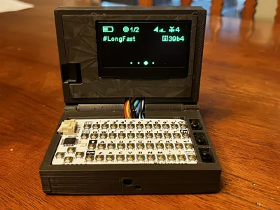
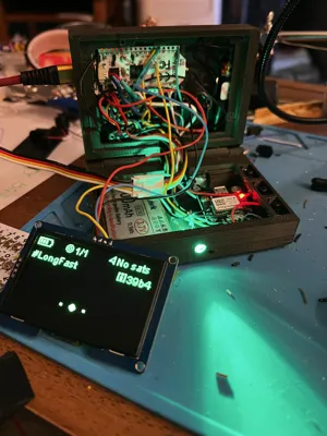
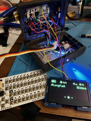
This folding case fits the Heltec ESP32 V3 LoRa board intended for use with Meshtastic. The model prints very smoothly in PLA-CF and other filaments, as shown is printed in ASA for better durability. The goal was to have a larger screen, internal antenna, external and internal features, and to fit as many modules as possible and still fold to fit in your pocket. (many pockets) and have flashlight.
I have printed vertically with tree supports with success, for texture I printed with the interior of the cases face up with tree supports. 35% -50% infill . Print the screen cover with the post on the interior side vertical.
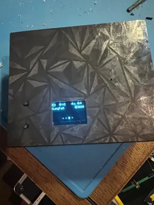
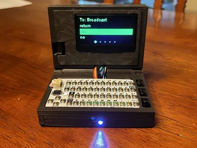
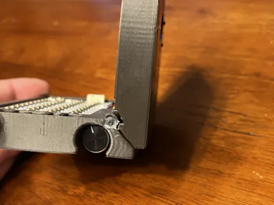
This model allows you to have a small external screen with the user and reset button, canned messages can be sent with case closed using the rotary encoder ( you can change this if you'd like), with the case open you can use the keyboard or rotary encoder for canned messages. Some instances may occur where it may be cleaner for the radio to use the rotary if your hands are dirty. The buttons as I have wired them allow you to enable/disable the buzzer and vibra motor independently without using the phone (after you have set them up through the app) and the third button is a flashlight. In my preference I wanted a smaller bright flashlight and larger notification using green light to show up better in the day time. If you want more light you can wire the larger led to be the flashlight; tip- when wiring the buttons pass the wires through the interior side of the button rail and pull the wires up through the middle of each hole (2 each) then solder to the buttons, install the buttons by pushing them in through the top of each hole in the rail after folding the flaps down to make a letter “n” shaped button. If you wanted to put a belt clip I would advise attaching the clip with the fasteners underneath the three buttons ( maybe drill out and heat set an insert) as there is “meat” on the bone in that area.
Tip- use the thermal tape on the back of the 2.42" OLED to prevent contact with the back of the radio board.
Parts List-
+ 10mmx2mm flat coin button type micro DC vibra motor [gpio40 →on/off button→ground] fits into pocket on bottom case next to the led
+12mmx9mm active buzzer 3-12v [gpio 45 to buzzer, buzzer negative to on/off button to ground] fits in the holder on top case
+3000 mah makerhawk battery ***slide the battery in the bottom case first before any other components as you will need to lay it flat diagonal across the bottom of the case and rotate it into its position, you will need to extend the battery cables slightly for most batteries.
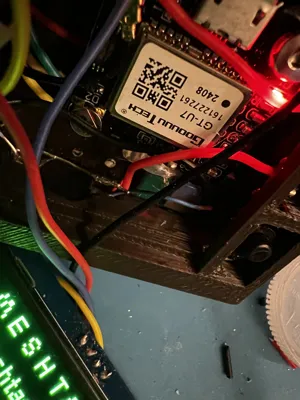
+GT-U7 Goouuu Tech GPS [ Tx→gpio 47, Rx → gpio 48, gnd→ ground, Vcc→3v Antenna fits in pocket in front right of bottom case and board can be mounted to post after battery is installed. Do not forget that although wiring to pins as mentioned, in the app you will set Rx to 47 and Tx to 48 ( they are the opposite of how they are wired for the app)
+ 3mm led (for notifications) and resistor- gpio 19
+2mm led (for flashlight) and resistor wire 3v to on off switch, wire switch to led
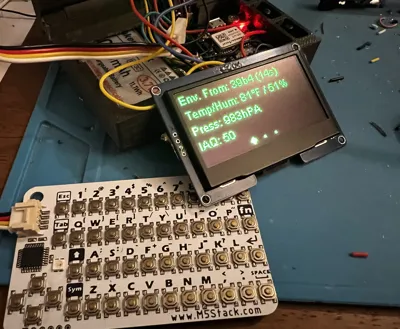
+ BME 680 environmental sensor ( can use BME/BMP 230) ****the keyboard wires into the sensor and sensor to radio [SCL→ gpio 42, SDA → gpio 41, Gnd → ground, Vcc→ 3v
+ 10 cm softwhip 10 Dbi antenna I put the antenna in and bent it into its position carefully before soldering any wires.
+ (3) on off buttons - Type BK 1208 self locking [ used for vibra motor, buzzer, flashlight]
+ 28 AWG wire
+ EC11 Rotary Knob [ Sw1 → gnd , Sw2 →gpio 7, A→ gpio 6 , B→ gpio 5, C→ground]
+ M2 screws [for the screen and for the clam shell, 25mm and 5-8mm]
+M2 Threaded Heat Inserts [for the screen]
+Thermal Vinyl Tape ( for the screen and radio board)
+ VHB Tape (for screen cover)
+ 2.42" I2C OLED SSD1309 [ SDA→ gpio17, SCL→gpio 18, Gnd→ground, Vcc→3v]
+M5Stack Card KB- [ white wire → SCL on BME, yellow wire → SDA on BME, Black→ ground, Red→Vcc]
+ Hot glue- optional but recommended for the soldered connections to prevent contact. use on the rotary, gps, BME sensor, the back of the radio on pins 17 and 18 and anywhere else you see necessary.
+ Liquid Tape- optional
I left my screen wires a little long so when I pull the screen out to I can lay it down flat by pulling the wires over the top of the case ; I would suggest lengthening the battery wires closer to the battery instead of closer to the connector unlike what I did shown here as it takes up valuable space. I got it to work in this case but in retrospect Ill do it differently next time. I suggest soldering your modules and accessories after installing the battery, get your items into position to determine wire length and then put the buttons in place, insert the heltec board and hold in place with piece of tape across the back while you figure your pieces then solder the radio board last. Don't forget to put tape across the back of the 2.42 oled and secure your solderings with hot glue and or liquid electrical tape . Hot glue is neat because if necessary you can usually peel it off and rework something. Dab of hot glue at least on pins 17 and 18 because of the vicinity of the internal OLED.
You may remix these cases and share/build for friends or family but these or their likeness may not be used commercially without my explicit consent, and probably some money/proceeds :) Give some credit when appropriate please. Thank you. Happy Meshing
tips appreciated, thank you
Ltc M9w6KnukrPLUT9EZ5YaWtoJe54ZeywG27B
Btc 36dyxiCZzDV4oUDWYgdHkCSjLnBy3LSQDo
Eth 0x6c09555632e886Bb14A2c71E5A8a6c9514e9572F
USDC 0x4e6B8686ACB3f5dcA38AD44d58f8f2Ef85aC138d
Cheers.
Comment & Rating (0)