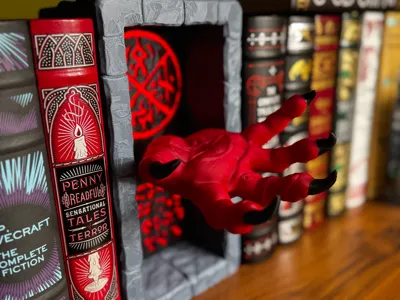
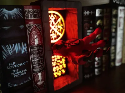
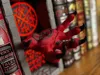
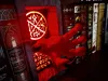
Hand of Terror - Diablo inspired Booknook


Print Profile(2)
Bill of Materials


- 1 x 1: Quality Adhesvive
Description
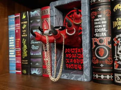
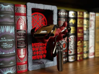
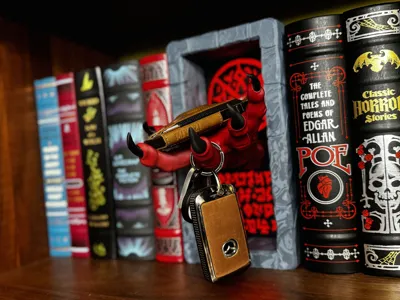
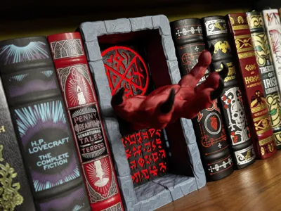
Inspired by the 30th Anniversary of the video game Diablo, this book nook features a demonic hand reaching out from a cryptic stone portal. Use it as general decor or as a holder for things like keys, your wallet, the extracted hearts of your enemies, or anything else small enough to fit in your hand.
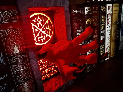
Designed to print in multiple parts with minimal assembly. The arcane writing and symbology on the rear of the portal can be lit from behind via a press-fit light box that features different mounts for lighting options. Use tea lights or the LED lamp kit from Maker's Supply, or use nearly any adhesive-backed LED strip cut to size.
There are two print profiles, one for use with AMS systems and one without. The AMS profile combines some of the parts and adds some painting to parts like the hand. In either case, only three colors of filament are used to complete the piece. Assembly for the AMS parts follows the same instructions as the Non-AMS version listed below, with a couple of steps (like gluing the claws to the hand) taken out of the equation.
Printing Information:
Plate #1: Portal Walls
This plate contains the stone walls of the portal. It is designed to be printed without supports. The profile uses 2 walls and 5% gyroid infill, as this part does not bear any sort of load. I recommend printing this part in a medium to dark shade of matte grey. The “bottom” edge of this part is flat, to ensure it rests cleanly on your bookshelf, so keep this in mind during assembly. In the AMS profile, this plate is combined with plate #2, as these are printed as a single piece.
Plate #2: (Backplate, Swap @ Layer 3)
This plate contains the portal's backplate, it is beveled to allow flush seating into the walls, but does not attach to it directly. It will be held in place via friction pressure during assembly. There are four screw holes sized to accommodate clear passage of M3 screws. This is the only multicolor part in the NoAMS profile. Start out with the color you want the light passthrough to be (use white if using a color-changing RGB LED strip) - I recommend a darker red like Bambu's Maroon Red or eSun/3DHOJOR Fire Engine Red. The pause will trigger at the start of layer 3, where you can change the filament out for another color. I recommend a matte black for contrast, but grey also works. Or use whatever color you want, I'm not the boss of you.
Plate #3: (Light Box)
This plate contains the backlight box. It serves both as a lightbox and a counterbalance/stabilizer for the front of the book nook. There are several different lighting options you can choose from. The profile settings for this part are two walls with 5% gyroid infill. The top connector pieces, which press-fit into the Walls part during assembly, have modifiers that increase their wall thickness and extend those walls into the model for additional strength. I recommend printing this in black. There are also two covers for the tea light sockets to prevent light from spilling out, you can exclude these if using tea lights.
Lighting Options (more information and photos below, in assembly instructions):
- Two tea lights of any color (KC008, KC017, KC018) from Maker's Supply.
- The LED Lamp Kit MH001 from Maker's Supply.
- Nearly any adhesive-backed LED strip cut to around 1m in length
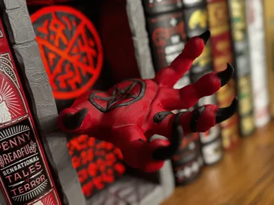
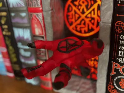
Plate #4: (Hand of Terror)
This plate contains the Hand of Terror. The hand prints without supports. I have not had any problems printing this part multiple times while iterating it's design on a P1S, but if you're using an A1 or another “bed slinger” you may wish to add a brim and disable “reduce infill retraction” in your slicer to help ensure the part does not get knocked over during printing. It's important that you make sure your bed has been thoroughly cleaned with a grease-cutting detergent like Dawn (US) or Fairy (UK/EU) to ensure proper bed adhesion before printing this part. I recommend printing this in a darker red, like Bambu's Maroon Red or eSun/3DHOJOR Fire Engine Red.
In the AMS profile, this plate is combined with plate #5, as the claws are printed as part of the hand.
This part contains four screw holes, sized at 2.9mm and 4.7mm. The 2.9 mm holes (top and bottom) are meant for directly driving M3 screws into the part, while the 4.7mm holes are meant for M3 heat-set inserts. You can use both, but it's really not necessary. These are present as options based on your preferences. You can also choose to just glue the hand in place, with or without the aid of screws. More information in the assembly instructions below.
Plate #5: (Claws)
This plate contains the hand's claws. I tried several different ways to key these to make them simpler to attach, but none of my attempts accomplished this, and it wound up being easiest to leave them unkeyed. The profile will print these at adaptive layer height to help reduce the layer lines introduced by their orientation. The claws are oriented on the plate in finger order, from thumb to little finger (left to right), same as the orientation of the hand. It can be difficult to tell these pieces apart. To help assist with this, small letters have been added to the bottom of three of the claws as negative modifiers. You should be able to tell the Thumb and Little finger apart without assistance. I have faith in you.
- Thumb - No marking
- Index Finger - “I”
- Middle Finger - “M”
- Ring Finger - “R”
- Little Finger - No marking
These parts require support, thanks to my poor design skills. The profile sets the top Z distance to .27mm, three top interface layers. This makes the supports easy to remove, but there may still be some interfacing material left attached to the part, particularly on the index finger.
Assembly:
Step 1: Glue the claws in place
This is pretty straightforward. After cleaning off any interfacing material left behind (as I forgot to do in this photo) add a small amount of glue to each “socket” and place the appropriate claw and hold it in place until it sets. It's best to test-fit each piece before applying glue, so you get a feel for how they fit.

I personally do not have success with most superglues and PLA. They dry fast, but don't really hold a great bond. I recommend using adhesives like E6000 Jewelery and Bead (shown here, very tacky and holds well quickly) or Weld-On 16 (which is solvent-based kind of “syrupy” and tends to run - take care when using). None of the claws weigh much, and should hold fairly well in a short amount of time with most adhesives.
I'm not patient enough to allow glue to fully cure before handling, but you should be.
Step 2: Install your chosen lighting
As mentioned above, there are three different lighting options you can use.
- Two tea lights of any color (KC008, KC017, KC018) from Maker's Supply. These are a snug fit and will require a little force to press them in. LED tea lights in general do not have a standard size and it's unlikely that ones sourced elsewhere will fit. These have a nice flickering effect.
- The LED Lamp Kit MH001 from Maker's Supply. Feed the USB cable through the hole near the bottom and then slide the lamp into the center mount and press it into place. Friction should keep it there.
- Nearly any adhesive-backed LED strip cut to around 1M in length. I used a cheap 1M (3.2ft) Cob LED strip from Amazon in the examples below.

If you're not using tea lights, use the included caps to close the holes from the inside to prevent light from spilling out. The simply press-fit into place with a small amount of force.

Step 3: Attach the hand to the backplate
Firstly, decide what method you want to use to attach the hand. Two sets of screw holes are provided, one for Voron-style M3 heat-set inserts for use with 6-8mm screws (left/right) and one without (top/bottom) meant for M3x12-20mm screws. Either one of these will work perfectly fine, you do not need to use both. If using the standard screw holes, I recommend using self-tapping screws, but regular socket cap or button head screws will also work.
If you've chosen heatset inserts, do that first, and then press the hand into the void that's present on the backplate.

Then drive your chosen screws in from the back to secure it in place.

Step 4: Press fit parts to complete assembly
Set the backplate with hand on top of the light box. Make sure it's correctly oriented.

Place the walls over the hand horizontally.

Then turn vertically, making sure the flat end faces the bottom. Make sure everything lines up, and then press down firmly on the walls to secure them to the lightbox, with the backplate wedged between. The backplate will self-align to some extent.

Step 5: Assembly complete
That's it. You're done. Plug in the light box and turn it on.

_____________________________
All of my original models are free to be remixed with attribution and used commercially.
Feel free to sell or give away prints, or use them in your marketing materials in any way you like.
Support a free and open 3D printing community.
Remixes of others' models are shared using the same license as the original work.
Comment & Rating (2)