
P2S - V2 Cover for Z-axis and Bottom Openings
Print Profile(4)


Description
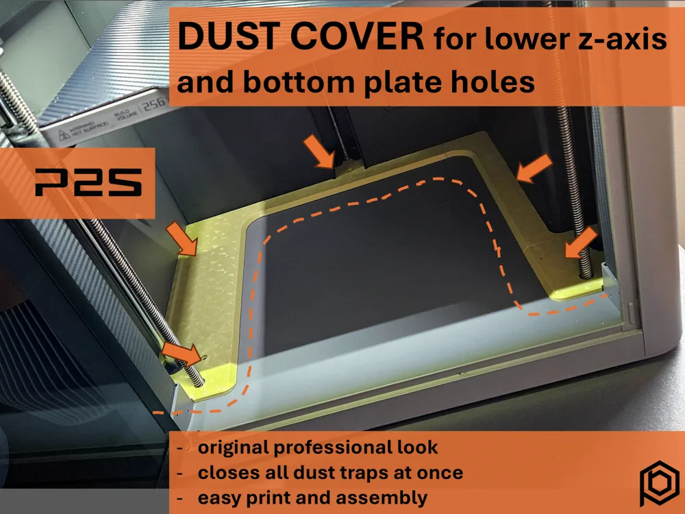
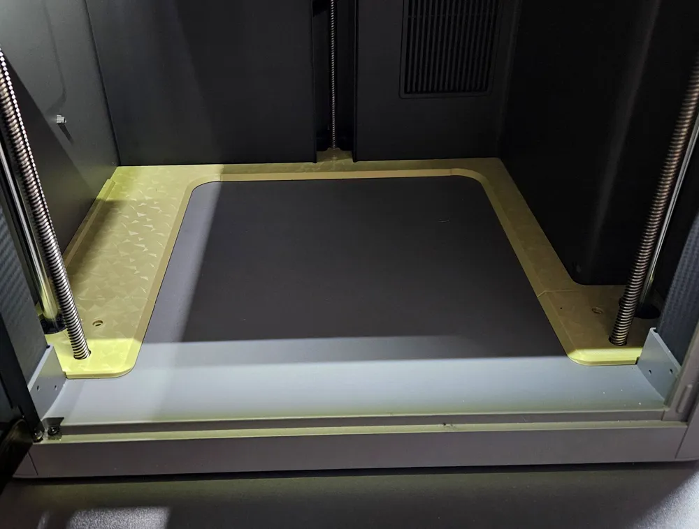
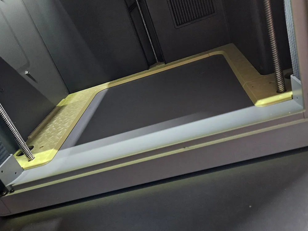
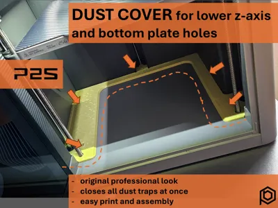
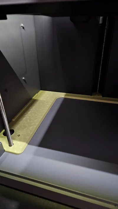
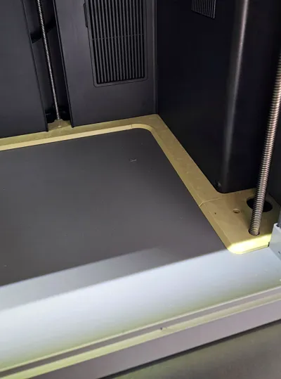
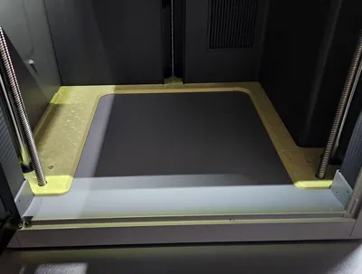
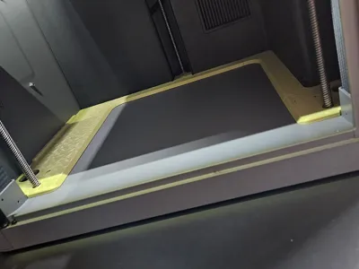
Cover for the Z-axis and bottom openings V2
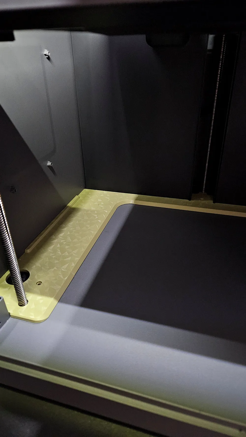
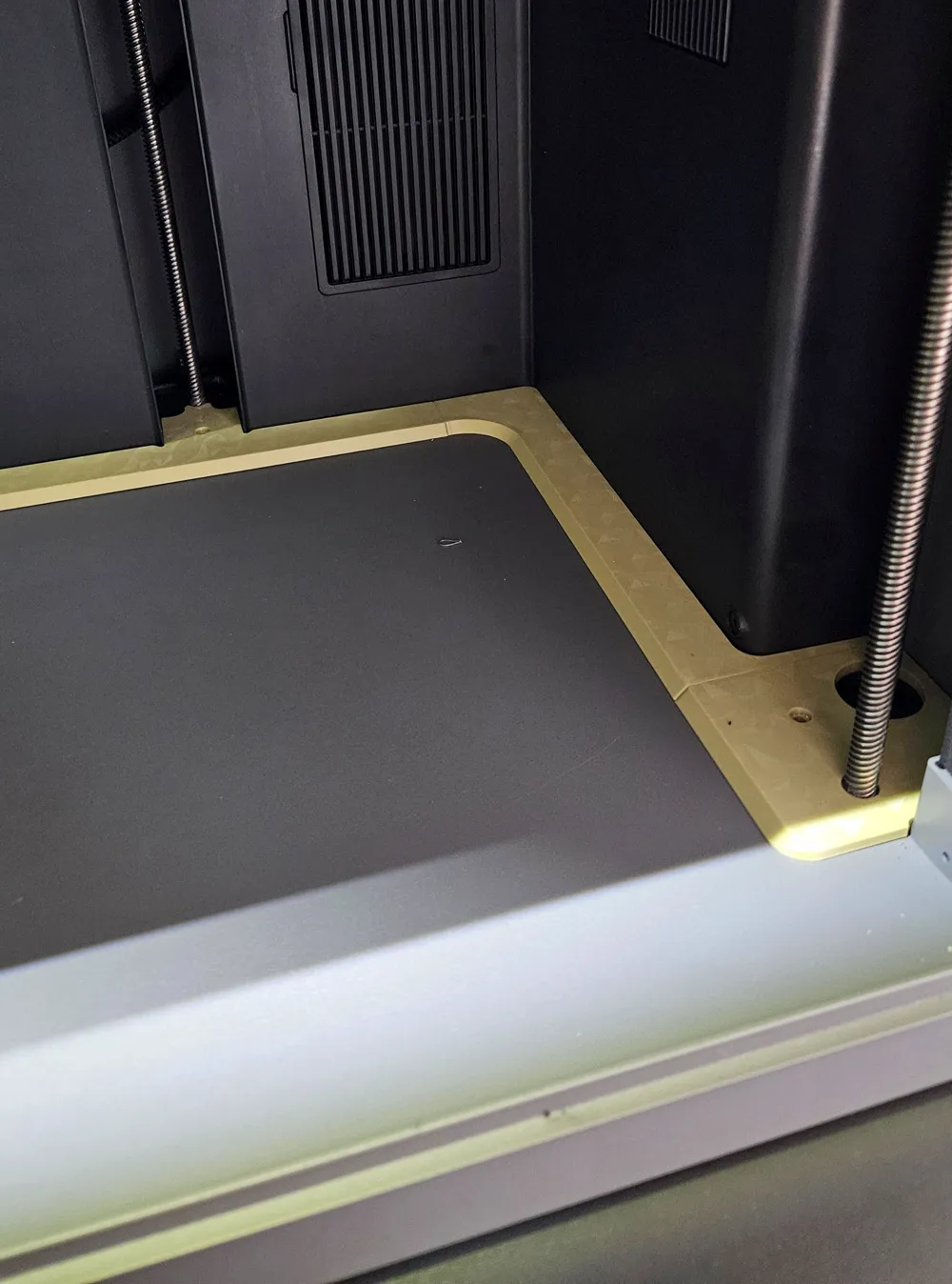
This is the second version of my Z-axis bottom cover. The improvements are mainly the surrounding cover, which integrates even more aesthetically into the overall design. The last hole on the right side is now covered. Also, the sticker on the left side is no longer visible.
I have precisely matched these parts to my printer's dimensions. Due to tolerance variations, some parts may not fit perfectly on a few models. I would need your support here; please let me know if there are any issues, such as parts getting stuck etc. 😉
There is a version for PLA and for PETG
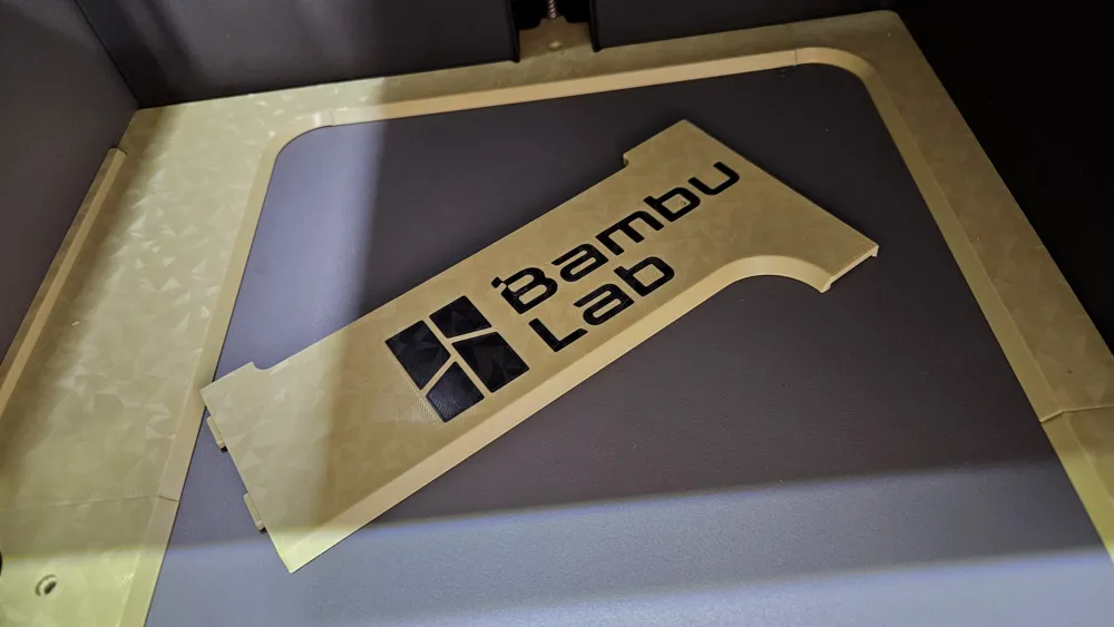
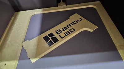
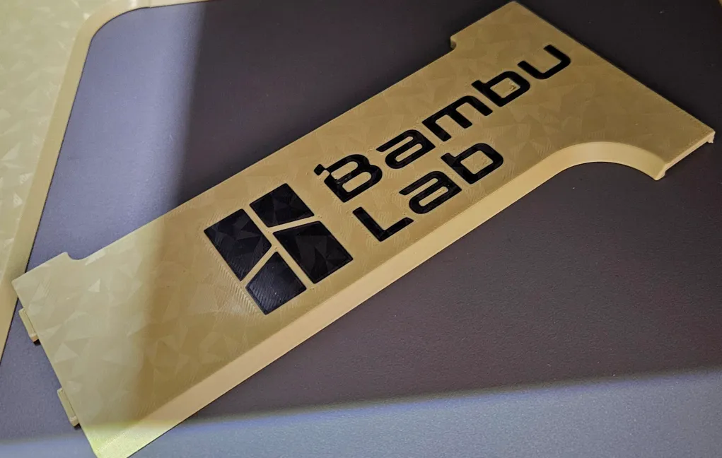
Additionally, there is an AMS version with the BambuLab logo for each
Boost Me (for free)
Please leave a boost if you like the part. This is really helpful to simply get seen. And I would love to help you further with great content. Thank you!!
Assembly
The assembly is basically the same as for the V1 version. Therefore, I have used the same pictures here.
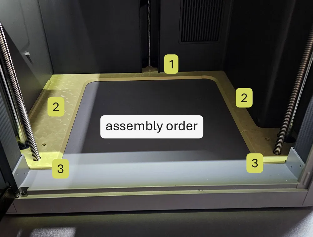
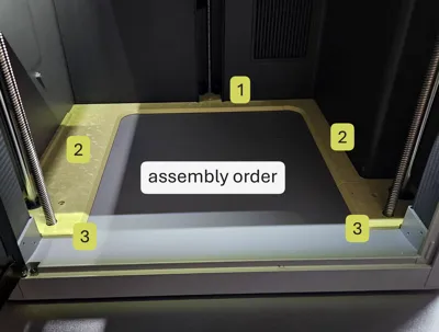
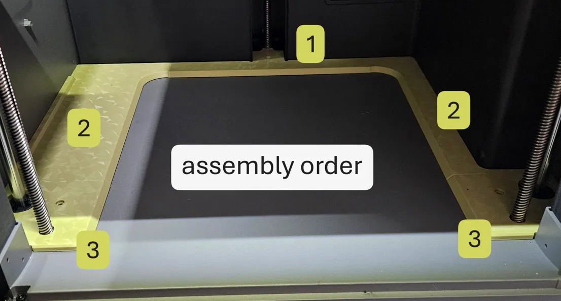
The only thing you need to pay attention to is the assembly order:
- rear axle cover
- left and right covers
front axle covers left and right
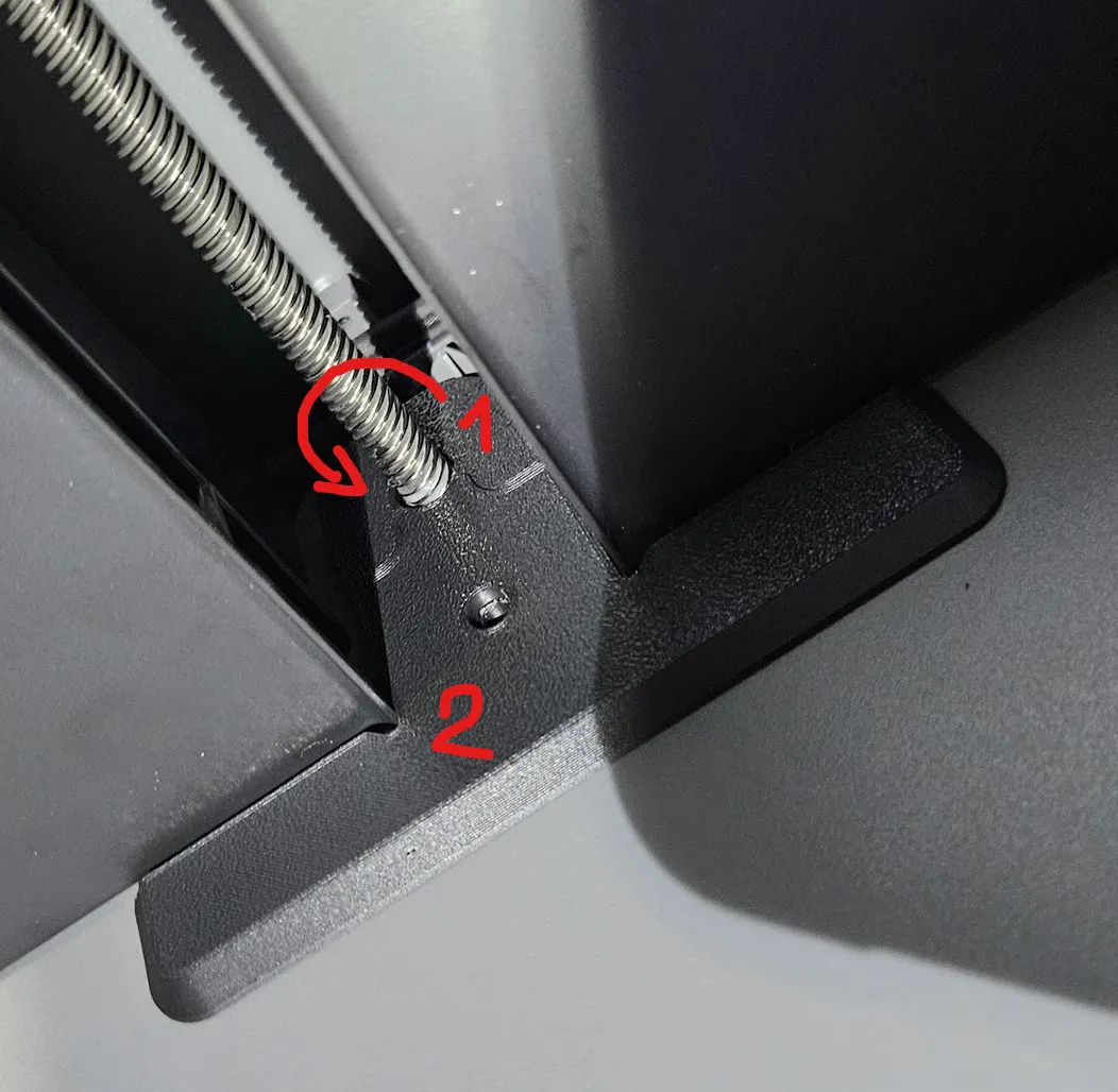
1.) For the rear cover, first attach the small part to the spindle and then rotate it around it.
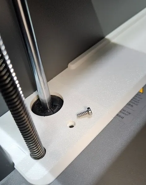
Then attach the front T-shaped part and fix everything with a 3x8mm self-tapping screw (those from the transport lock are ideal).
2.) the side covers are then simply placed on and positioned
3.) for the assembly of the front corners, simply place the small corner element and then clip the larger corner element onto it. Beforehand, ensure that the support structures on the “puzzle elements” are cleanly removed.
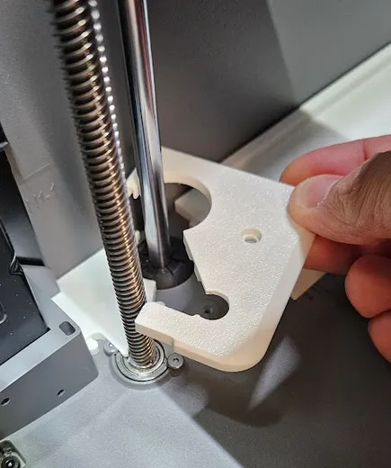
Finally, secure again with self-tapping 3mm screws (8mm length) in the existing hole
License

You shall not share, sub-license, sell, rent, host, transfer, or distribute in any way the digital or 3D printed versions of this object, nor any other derivative work of this object in its digital or physical format (including - but not limited to - remixes of this object, and hosting on other digital platforms). The objects may not be used without permission in any way whatsoever in which you charge money, or collect fees.


Comment & Rating (171)