Official DabTray - Pocket Temper


Print Profile(1)
Description
Boost Me (for free)
Help a brother out! Your boosts make the difference. Let's put one of these at every great sesh!
This is an adaptation of Officialdabtray's original design Published on Thingiverse here - https://www.thingiverse.com/thing:6955770
Official DabTray Products are now Open Source!
Download, make, remix, sell, i don't care! Just please credit me and send people to my Instagram! @OfficialDabTray
Assembly Instructions below!!
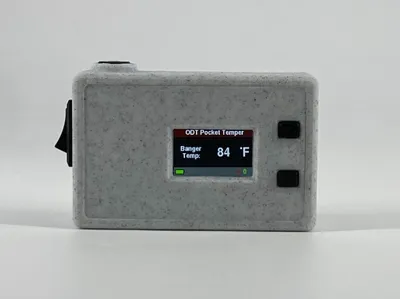
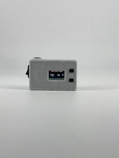
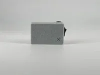
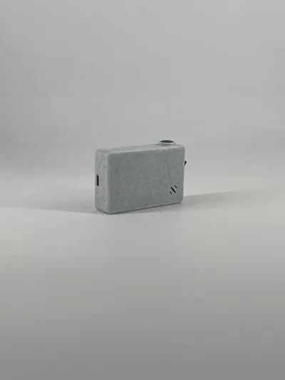
The ODT Pocket Temper:
The Pocket Temper is a pocket sized d@bbing thermometer meant to temp your glass quartz banger and let you know when its the desired temperature to go in.
It features a rapidly refreshing temperature read out, color changing temp indicator, F/C Temp readout, a user programmable alarm, and auto off feature.
Below is all the info needed to print, build, and program the temper.
Ive included amazon links for items that will work to create this unit, along with links to all other resources needed and instructions. Feel free to message for any info. You will need to know how to solder and have a soldering iron to make the temper. The hardest part is getting the ESP32 to work with Arduino IDE and programming it, but ive included videos (not made by me) with instruction on how to do it.
There is an adjustable stand for the temper that you can also make, here is the link:
Assembly Instructions:
- First print the 3 parts obviously.
- Solder the sensor and buzzer to the board
- Youll want each wire to be 4in long. Strip the ends.
- For soldering the holes on the board its best to fill the hole with solder, then with the iron on one side melt the solder in the hole again and press the stripped wire in through the other side pulling the iron away as the wire goes in.
- Here are pinout instructions for the sensor:
(Sensor - Board)
VIN - 3.3V (never connect to 5V, because ESP32 use 3.3V logic!)
GND - GND
SCL - GPIO 22
SDA - GPIO 21 - For the buzzer use esp32 holes 25 and ground. It doesnt matter with pin on the buzzer the wires go to.
- Next cut the plug on the end of the battery and solder the battery wires to the plug that came with the esp32
- Solder the 2 black wires together and leave the 2 red ones hanging to be connected to the switch.
- Add an extra red wire to the end of the small red wire that comes off the battery. You need more length to reach and solder to the on/ off switch.
- Next program and setup the ESP32 in Arduino IDE and load the code from the link below into the IDE.
- Video links below on how to do this, its kinda annoying so watch the videos carefully
- Youll need to install the needed packages needed for the code. Go to sketch, included library, then manage libraries at the top. Youll need to install the MLX90614 package by Steve Marple, the TFT_eSPI package by bodmer, exButton by ArduinoGetStarted, and ALog by Andrew Wickert
- Once packaged are installed, plug in the wired up esp32 and select the correct COM port under tools and click upload.
- Next install the battery in the lower right corner of the temper housing. Make sure the wires are coming out the top left side of the battery so they point directly to the switch hole and stay out of the way of everything else.
- Solder the 2 red ends (one coming from battery and other from small plug) to the switch. It doesnt matter witch wires goes to which prong on the plug. I just like to make sure the up line is facing up.
- After soldering leave the switch out of the housing. Its hard to install the sensor if you press the switch in now.
- Next install the sensor and board into the housing.
- First plug the small battery connector into the bottom of the board and insert the board into the housing by pushing the charging port into its small hole first and the pushing the back down into the stand off. Have the sensor wires going up up the board with the buzzer wires doing the same going down inbetween the sensor wires. If it feels like the board isnt going down into the standoffs correctly, adjust your wire. There is enough room for everything, you just gotta finesse it.
- Push the sensor into the sensor hole with the wires going right with the excess sitting in the slow above the board.
- Push the buzzer into the buzzer hole on the bottom, you will need to bend the prongs so they arent sticking straight up.
- Last push the soldered on/ off switch into the switch hole.
- Last you just need to glue it all together.
- Use hot glue to hold the sensor, on/ off switch, and buzzer in place.
- Before you put the lid on, make sure the wires are routed correctly and everything fits. Also make sure the screen is in line with the screen hole on the lid. The screen is held down with double side foam tap and is some times not in line. If its not in line with the hole, VERY VERY VERY CAREFYULLY get under it with a wedge or knife and pry it off the tape so you can adjust and push the screen back down. It is VERY EASY to break these screens, so be super careful and use a heat gun to warm up the double sided tape if having trouble. If you use a heat up also be VERY CAREFUL not to heat the sreen too much. I like the heat it up with the screen turned on, so if its getting too hot youll seen the screen image starting to fade or go black. Once that happens stop heating and try to pry it up again.
- Put thick super glue on the 4 corners and top of the post that holds the esp and press the screen on. Make sure not too use too much as it can ooze out the corners or onto the screen. You can also use hot glue for this if you dont have super glue or your super glue is not thick enough.
Amazon Links:
- TTGO ESP32: https://www.amazon.com/dp/B099MPFJ9M?ref_=ppx_hzsearch_conn_dt_b_fed_asin_title_1&th=1
- MLX90614 BCC Sensor: https://www.amazon.com/dp/B0C7KZH2VJ?psc=1&ref_=ppx_hzsearch_conn_dt_b_product_details_1
- LiPoly Battery: https://www.amazon.com/dp/B0BJPPNN6B?ref_=ppx_hzsearch_conn_dt_b_fed_asin_title_8&th=1
- Switch: https://www.amazon.com/dp/B01N2U8PK0?ref_=ppx_hzsearch_conn_dt_b_fed_asin_title_2
- Alarm: https://www.amazon.com/dp/B082R4S4N8?ref_=ppx_hzsearch_conn_dt_b_fed_asin_title_1
Other Links:
- Temper Code: Code attached to downloaded files on Thingiverse
- Setup ESP32 in IDE: https://www.youtube.com/watch?v=UE1mtlsxfKM&t=243s
- ESP32 in IDE info: https://www.hackster.io/patrick-fitzgerald2/ttgo-t-display-77905d
- MLX90614 info: https://www.instructables.com/ESP32-and-Infrared-Temperature-Sensor-MLX90614/
YT -
License
You may create derivative works based on this object, provided that all such derivative works are published exclusively on the MakerWorld platform and include proper attribution to the original creator. You may not share, upload, host, distribute, or publish this object—or any derivative work of this object—on any other digital platform, marketplace, or distribution channel. Commercial use of this object and any derivative works is strictly prohibited. This includes, but is not limited to, selling, renting, sublicensing, or using the object in any context in which you receive monetary compensation or other financial benefits.
Comment & Rating (1)