Parametric Furniture Foot/Leg Generator


Print Profile(1)

Description
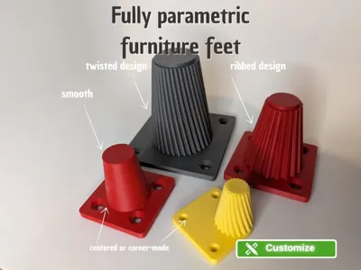
A fully parametric Japandi-style furniture foot that can be completely adapted to your furniture via the MakerWorld Customizer. The conical foot combines the minimalist aesthetic of Japanese-Scandinavian design with sophisticated engineering for maximum stability during 3D printing. Please consider the disadvantages of the printing process when choosing materials and furniture, and select carefully, avoiding tall, heavy bookshelves without wall mounts.
Boost Me (for free)
If you like my designs, I would appreciate a boost. Thank you!
Design Concept
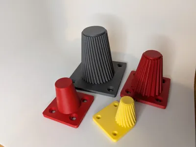
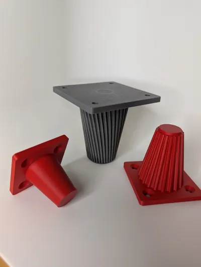
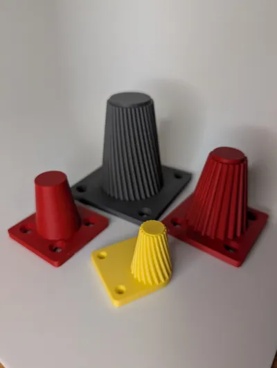
The foot consists of a square mounting plate with countersunk screw connections and a conical body that tapers upwards. Fine Japandi ribs run around the outside, giving the foot its characteristic look – and also serving as structural reinforcement. The ribs can be twisted, drafted, and rounded at the outer edges. If you prefer a simpler look, simply set the rib count to 0 to get a smooth cone.
At the top sits a small standoff ring that protects the ribs from direct ground contact and forms a clean, defined standing surface.
Two Mounting Modes
Centered (Standard): The foot is centered on the plate, with four screw connections in the corners. Classic for table and cabinet legs.
Corner Mode: The foot is positioned precisely in one corner of the plate. The corner automatically rounds with the total radius of the foot (cone + ribs), so that the ribs seamlessly transition into the plate edge. In this mode, there are three screw connections – the corner under the foot is skipped. Perfect for shelves, sideboards, or side tables where the foot should sit flush with the edge.
Internal Reinforcement – Clever Use of Infill
The special feature of this design is the internal reinforcement structure, which is cut as a negative mold from the solid cone. This keeps the foot solid, and it is filled by the slicer with infill (ideally Gyroid, 20–30%).
The reinforcement consists of:
Central Bore: A conical hollow cylinder in the center of the foot. This creates a closed ring – the most stable cross-sectional shape. The bore reduces material in the core, where it contributes least to bending strength.
Radial Slots: From the ring, slots radiate outwards towards the cone wall. A minimum wall thickness (cone_wall_thick) always remains between the slot and the outer wall, ensuring the shell remains intact – whether with or without ribs.
How does this affect strength? The slots create additional walls internally. The slicer prints perimeter lines along each slot edge, which are significantly stronger than pure infill. The more slots, the more internal walls are created – and the stiffer the foot becomes under compressive load. At the same time, the remaining void is filled with Gyroid infill, which effectively absorbs shear forces. The result: a foot that is significantly more stable with 20–30% infill than a completely hollow or completely solid print.
The entire reinforcement structure begins at Z = 0.45 mm (after approx. 3 print layers) so that the walls of the slots and the bore are connected to the first layers of the base plate from the start. This prevents delamination at the critical transition point between the plate and the cone.
All Parameters at a Glance
Placement Mode – Placement
| Parameter | Description | Default |
|---|---|---|
| corner_mode | Foot in corner instead of center, 3 screws instead of 4 | false |
Mounting Plate – Base Plate
| Parameter | Description | Default |
|---|---|---|
| plate_size | Side length of the square plate | 70 mm |
| plate_thick | Plate thickness | 5 mm |
| plate_corner_r | Plate corner radius | 3 mm |
Mounting Holes – Mounting Bores
| Parameter | Description | Default |
|---|---|---|
| hole_edge_dist | Distance from bore center to plate edge | 10 mm |
| hole_dia | Through-hole diameter | 5.5 mm |
| hole_sink_dia | Countersink diameter | 10.5 mm |
| hole_sink_angle | Countersink angle | 90° |
Cone – Cone
| Parameter | Description | Default |
|---|---|---|
| foot_h | Foot height without plate and standoff ring | 100 mm |
| foot_d_bottom | Diameter at bottom (plate side) | 50 mm |
| foot_d_top | Diameter at top (standing surface) | 30 mm |
Standoff Ring – Standoff Ring
| Parameter | Description | Default |
|---|---|---|
| standoff_h | Height of standoff ring at top | 2.5 mm |
| standoff_extra_r | Protrusion beyond the cone | 1.0 mm |
| standoff_chamfer | Chamfer on the outer top edge | 0.5 mm |
Japandi Ribs – Japandi Ribs
| Parameter | Description | Default |
|---|---|---|
| rib_count | Number of ribs, 0 = smooth cone | 36 |
| rib_wall | Rib wall thickness | 2.4 mm |
| rib_depth | Depth of ribs radially outward | 2 mm |
| rib_draft | Taper bottom→top, 1 = uniform | 1 |
| rib_twist | Twist in degrees, top = 0°, bottom = value | 0° |
| rib_fillet_r | Fillet at rib base to cone | 0.6 mm |
| rib_round_r | Rounding of rib outer edges | 0.5 mm |
Internal Reinforcement – Internal Reinforcement
| Parameter | Description | Default |
|---|---|---|
| inner_hole_dia | Diameter of central bore, 0 = none | 16 mm |
| inner_slot_count | Number of radial slots | 6 |
| inner_slot_width | Width of slots | 2.0 mm |
| slot_inner_gap | Distance between bore and slot start (ring) | 2.0 mm |
| cone_wall_thick | Minimum wall thickness of cone shell | 2.0 mm |
| slot_fillet_r | Radius at outer slot corners | 0.8 mm |
| struct_z_start | Reinforcement starts at this Z-height | 0.45 mm |
Screw Reference
The default values are suitable for M5 countersunk screws (DIN 7991 / ISO 10642). For wood screws / chipboard screws with countersunk heads, here are the common dimensions:
| Screw Type | hole_dia | hole_sink_dia | hole_sink_angle | Typical Length |
|---|---|---|---|---|
| M5 Countersunk (DIN 7991) | 5.5 | 10.5 | 90° | 16–30 mm |
| M4 Countersunk (DIN 7991) | 4.5 | 8.5 | 90° | 12–25 mm |
| Spax / Chipboard 3.5 mm | 4.0 | 7.5 | 90° | 16–40 mm |
| Spax / Chipboard 4.0 mm | 4.5 | 8.5 | 90° | 20–50 mm |
| Spax / Chipboard 4.5 mm | 5.0 | 9.5 | 90° | 25–60 mm |
| Spax / Chipboard 5.0 mm | 5.5 | 10.5 | 90° | 30–80 mm |
Tip: For wood screws, choose a bore 0.5 mm larger than the thread diameter so that the screw passes through freely and the thread only grips the furniture wood.
Print Recommendations
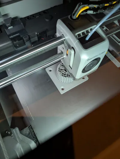
- Orientation: Plate on build plate – ready to print
- Layer Height: 0.2 mm
- Walls/Perimeters: 3–4
- Infill: 20–30% Gyroid (optimally uses the internal reinforcement)
- Top/Bottom: 4 Layers
- Supports: Not needed (plate lies flat, cone has no overhangs)
- Material: PLA, PETG or ASA – depending on load
License
You may create derivative works based on this object, provided that all such derivative works are published exclusively on the MakerWorld platform and include proper attribution to the original creator. You may not share, upload, host, distribute, or publish this object—or any derivative work of this object—on any other digital platform, marketplace, or distribution channel. Commercial use of this object and any derivative works is strictly prohibited. This includes, but is not limited to, selling, renting, sublicensing, or using the object in any context in which you receive monetary compensation or other financial benefits.
Comment & Rating (1)