
Dewalt Tstak 'Table top' / connector brackets




Print Profile(0)
Description
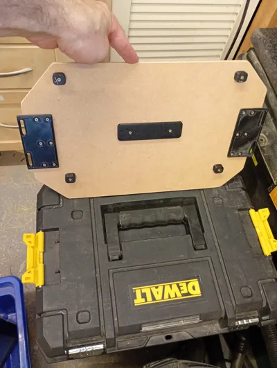
Set of designs to make a table top or connector for on top of a DeWalt Tstak toolbox. I used one to create a connector to hold my Ryobi Vacuum on top using https://www.printables.com/model/1044158-ryobi-link-wall-mount-single-cleat as shown in the photos.
I have printed in PLA+ and it seems to be holding up well (was initially as a prototype but has been working fine so haven't reprinted in PETG yet but would advise PETG for strength)
You will need to print 2 brackets that the tstak clips will grip onto as a minimum.
Have included designs for feet that fit into the recesses on the top of the toolbox to help lock it in place and a spacer so thinner board is supported in the middle if necessary.
You will need to supply a board to use as the top - MDF or Plywood works well.
NB - My photos show my Mk1 version and designs have now been updated, moving the screw positions on the brackets slightly and adding 2 screw holes to the feet to prevent spinning.
Assembly Instructions
Items to Print
- 2 x Brackets - I printed with 5 walls and 50% infill for strength
- 4 x feet
- 1x spacer (optional)
Items Required
- 12 screws for the brackets - mine were 2.5 x 10mm but I was only used 6mm board - I advise using the longest you can get away with without going through your board ;-)
- 8 screws for the feet - mine were 2.5 x 12mm - again use as long as you can
- 2 screws for spacer - mine were 2.5 x 10mm
- some double sided tape
- Cut your board to size - 394mm wide, the depth is up to you but I cut mine to 250mm to fit my vac
- Screw on the brackets aligning the holes with the edge of your 394mm board as indicated by the red arrows in the diagram. Suggest initially just using a couple of screws till fit is checked in step 3
- Check that the board fits correctly and the tstak clips fit into place.
- Remove board from toolbox.
- Add a little double sided tape to the bottom (non countersunk) of each foot
- Place feet, sticky tape up, in each of the indents on the top of the toolbox
- Carefully lower board into place, press to connect tape on feet and then carefully remove taking care not to move the feet position, screw into place.
- Check fit is still ok and then remove board again
- Add a little double sided tape to the bottom (non countersunk)of the spacer and then place in position near the handle, tape again facing up.
- place board back into position and press to connect spacer. Carefully remove board and screw spacer into place
License



Comment & Rating (0)