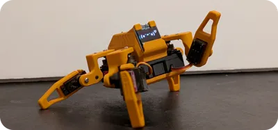
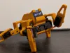
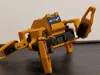
Sesame Robot Cat (Dog) - Mini Quadruped


Print Profile(2)
Description
Sesame is an accessible Open-Source robotics project based on the ESP32 microcontroller system, with an emphasis on expression and movement. This project is designed for makers and engineers of all skill levels! Sesame offers a dynamic platform designed to start working with walking robots. To build a sesame robot, you will need basic soldering skills, $50-60 in hardware components, access to a 3D printer, and a basic understanding of Arduino IDE.
- Quadruped Design: Uses 8 servo motors (2 per leg) to achieve roughly 8 total degrees of freedom.
- Emotive Display: Features a 128x64 OLED screen acting as a reactive face that syncs with movement.
- Fully Printable: Designed entirely for 3D printing in PLA with minimal supports.
- Network Connectivity: Connect to your WiFi network for remote control and API access.
- JSON API: RESTful API for programmatic control from Python, JavaScript, and more.
- Conversational Faces: Expressive emotion library with talk variants for voice assistant projects.
- Sesame Studio: New animation composer software to easily create custom movements.
- Sesame Companion App: Python application for voice control and advanced interactions.
- Serial CLI: Control the robot and trigger animations via a Serial Command Line Interface or the web UI.
- Pre-programmed Emotes: Includes animations for Walking, Waving, Dancing, Pointing, Resting, and more.
source and full guide here:
https://github.com/dorianborian/sesame-robot
Boost Me (for free)
Leave a boost if you like the project!
--------------
Getting Started
Follow these steps to build your own Sesame Robot:
1. Gather Parts
Check the Bill of Materials (BOM) for a complete list of required electronics and hardware.
https://github.com/dorianborian/sesame-robot/blob/main/hardware/bom/README.md
1a) Core Electronics & Control
- 1× Lolin/WeMos ESP32-S2 Mini: This is the recommended microcontroller for hand-wired builds. Its small footprint fits easily onto a standard prototyping board and features native USB-C.
- 8× MG90S Servos: The primary actuators (2 per leg). Make sure to get the ones with metal gears (MG90S) rather than plastic (MG90), as walking robots stress the gears heavily.
- 1× 0.96" SSD1306 I2C OLED Display (128x64): Used as the robot's animated face. It slides into the cutout on the top cover.
1b) Prototyping & Hand-Wiring Supplies
- 1× Small Protoboard / Perfboard (approx. 5×7 cm): This will act as your DIY distribution hub to host your ESP32-S2 Mini, power rails, and servo connectors.
- 8× 3-pin Male Headers (2.54mm pitch): You will solder these onto your perfboard to create a plug-and-play breakout matrix for your 8 servo plugs.
- 1× Rocker Power Switch (KCD1, Panel Mount): A standard small on/off toggle switch that snaps directly into the 3D-printed top cover cutout.
- 22 AWG Silicone Wire Kit: Used for your main high-current power and ground bus lines coming from the battery/power source.
- 30 AWG Silicone Wire Kit: Flexible, thin wire used for routing individual PWM signal lines from the ESP32 to the servo headers, as space inside the chassis is extremely tight.
- Heat-shrink Tubing Assortment: For insulating exposed solder joints on the OLED display, the power switch, and power connections.
1c) Power Supply Option
- 1× Bambu Lab 14500 7.4V 800mAh Li-ion Battery: The repository specifically recommends this battery pack because it is cheap, effective, and natively fits the 3D-printed internal frame.
- 1× Buck Converter (Step-Down Regulator): Needs to take the 7.4V battery input and output a stable 5V at a minimum of 3A to safely power the 8 servo motors and the microcontroller without brownouts.
- 1× JST XH2.54 Female Pigtail Connector: To cleanly bridge the battery plug into your custom power switch and perfboard without cutting the stock battery cable.
1d) Fasteners & Mechanical Hardware
- ~40× M2 × 5 mm Self-Threading Screws: Used for all plastic-to-plastic structural assembly, motor mounting, securing the OLED display, and closing the covers. (Getting an M2 variety pack is highly recommended).
- 10× M2.5 × 5 mm Machine Screws: Used strictly to attach the servo horns to the actual servo motor shafts. Note: The tiny screws included in standard servo bags are usually too short for the 3D-printed leg joints.
1e) Essential Tools for Hand-Soldering
- Soldering Iron & Leaded Solder (0.6mm–0.8mm): Leaded solder flows much easier for dense, tight perfboard work.
- Flux Pen: Crucial for making clean solder joints on the tight layout.
- Small Flush Cutters: To trim away excess component legs, servo lead lengths, or 3D-printed supports.
- Precision Screwdriver Set: For driving the small M2 and M2.5 hardware.
Next Steps for DIY Wiring:
Once you have these parts, you will solder the ESP32-S2 Mini onto the perfboard, bridge all 8 servo ground pins together, bridge all 8 servo V+ pins together (connected to your 5V power line via the switch/buck converter), and run individual 30AWG signal lines from the ESP32's GPIO pins to the respective signal pins on your 3-pin servo headers.
2. Print Parts
You can find a Printing Guide here:
https://github.com/dorianborian/sesame-robot/blob/main/hardware/printing/README.md
but you wont need it if you download the print profile (.m3f) with all parts included.
- Designed for PLA
- Minimal supports required
3. Build & Wire
Follow the Build Guide and Wiring Guide to assemble the frame and connect the electronics.
https://github.com/dorianborian/sesame-robot/blob/main/docs/build-guide/README.md
https://github.com/dorianborian/sesame-robot/blob/main/docs/wiring-guide/README.md
if you cant access the github pages, you find the build steps below:
Phase 1: Gathering all the parts.
Goal: Print the full shell set and collect every electronic, connector, and fastener before any soldering starts.
There are 11 printed parts (internal frame, top/bottom covers, joints R1–R4/L1–L4) plus 6–8 main electronic components depending on the wiring approach.
Here's what a complete set looks like:

Phase 1 checklist
- All plastic parts printed, and cleaned up.
- MG90 servos tested quickly on a servo tester or Arduino to catch DOA units.
- Power plan decided (USB-C PD vs. battery + buck) and matching connectors sourced (2× 14500 Li-ion cells in a 2× AAA holder fit the stock battery cavity).
- Consumables stocked: solder, flux, heat-shrink, zip ties, M2 hardware.
Phase 2: Electronics and Wiring

Goal: Build 90% of the harness on the bench so the frame install is quick.
- Open the wiring guide and pick the section that matches your build (S2 Mini hand-wired, Distro Board V3/V2, or Distro Board V1 legacy).
- Lay out every connector in the order shown on the wiring diagram before soldering; this keeps the data lines from getting crossed.
- Tin and solder the rails/buck converter first, then route signal wires. Leave generous length for the motors that terminate near the hips.
- This is optional but you can also label each servo lead (S0–S7) using tape flags as soon as it is soldered. Future you will thank you.
Warning
Stop before permanently wiring the power switch or OLED. Those final joints happen after the electronics are seated in the frame so you can dial the cable length exactly.
Phase 2 checklist
- Harness built per your wiring diagram with all joints strain-relieved.
- Buck converter trimmed to 5.1 V output and shrink-wrapped.
- Servo leads labeled and loosely bundled by destination.
- Power switch and OLED leads pre-cut but still un-soldered.
Phase 3: Hardware Pre-Assembly
Hip Joints
Goal: Pre-load the four hip joints (R1, R2, L1, L2) with one-sided servo horns so installation is tool-free later.
- Lay out the four hip joint parts. Find the one-sided servo horns from the servo motor bags (ignore the included extra screws).
- Notice the servo horn has a taller side and a shorter side. Press the shorter side into the hip joint. There should be just enough clearance to press this piece in flush.
- While holding the horn flat, drive an M2 × 5 mm self-threading screw (the ones with a larger gap between thread spikes) through the second hole in the horn and into the plastic until secure.

Tip
Do not over-tighten self-threading screws. Since the threads are plastic, over-tightening will permanently damage the hole.
Repeat for all four hip joints:

Important
Do not mount these joints on the servos yet. Calibration requires every motor shaft to spin freely.

Leg Joints
Slide each leg shell over its dedicated motor before the frame install. Use the built-in gap to route wires without pinching them.

- Feed the motor wires through the side slot.
- Push the motor into the side of the leg piece that has holes in it. Make sure the motor shaft is at the very top.
- Confirm the motor sits flush and use self-threading screws to permanently affix the motors into the leg pieces.
Repeat for the remaining legs.

Top Cover & Soldering
The next step is loading the OLED and power switch into the top cover. At this stage, we also do the minimal soldering required for the build.
- Power Switch: Press the battery switch firmly into the back slot of the top cover. DO NOT connect the wires yet.

- OLED Display: Apply a small amount of solder to the pin headers on the display (tinning). Using the pre-crimped JST connector wires, match the wires to their respective marks on the display and solder them.

- Battery Connectors (Main Board): Remove sheathing on the ends of the battery connector wires, tin them, and solder them to the battery pads on the main board in an L-shape pointing upwards. Make sure they do not go over the edge of the board, or the top cover won't fit.

- Install Display: Push the wired OLED display gently into its slot inside the top cover. Insert self-threading screws into the small screw holes beside the display to clamp it permanently in place.

Phase 3 checklist
- Hip joints pre-loaded with servo horns, not yet attached to motors.
- Leg pieces installed on every motor.
- Power switch and OLED display installed in the top cover.
- Battery connectors soldered to the main board.
Phase 4: Hardware Main Assembly
Goal: Seat the frame motors, route wiring, and secure the electronics stack so the robot is ready for calibration.
- Battery Holder: Insert the battery holder into the back of the internal frame piece. Route the red and black wires up the slot.
- Motor Installation: While holding the battery wires in place, insert the four remaining side motors. The motor shaft should be facing towards the outside of the internal frame.
- Insert motors at an angle and press them the rest of the way. Make sure not to pinch any wires at the bottom.
- Secure Motors: Use self-threading screws to permanently affix all four side motors to the frame.


Make sure the motor shafts are closest to the outer edge of the frame.

Installing the Main Electronics
Before dropping hardware in, trim or bundle any stray wires so nothing can flop into the servo gears and double-check that every connection exits upward.
- Pre-route any long wires upward so they naturally hug the future top cover.
- Lower the electronics harness into the cavity while keeping the USB port toward the rear.
- S2 Mini build: Screw the controller (and optional protoboard) directly into the frame using the provided mounting holes. If you built a small protoboard backplane, use the spare holes in the internal frame to secure it so the servo plugs are easy to reach later.

Calibrating & Running the Testing Firmware
Goal: Teach the controller where each motor sits so the walking poses land correctly.
Caution
Never run calibration with joints attached. A misaligned horn can stall or strip a servo instantly. All motor shafts should be free spinning at this point.
For S2 Mini Builds:
- Inspect the harness to ensure no bare conductors can short during testing. Add heat-shrink or tape where needed.
- Connect a reliable USB-C cable and flash sesame-motor-tester.ino from the debugging-firmware folder using Arduino IDE. If you have never flashed an ESP32 before, pause here and follow a quick tutorial so you are comfortable resetting/entering boot mode.
- Open the serial monitor. You should see the tester menu.
- Command all motors to 90°. Starting from Motor 0, plug its connector into the appropriate header. The servo should immediately whirr into the 90° position. Repeat for Motors 1–7. Skip to Step 4 below.
General instructions continuing:
- Refer to Diagram: Use the diagram below to associate motor numbers with their physical position. Ensure the frames are roughly oriented correctly.

- Plug Motors In: Starting with Motor 0, plug the connector into the corresponding board header.
- Crucial: Ensure the brown wire aligns with the ground rail! Upon plugging it in, you should hear it whir into life and hold position.
- Repeat for all 8 motors.
Tip
99% of the time, if your motor is moving in the wrong direction, crashing, or being sporadic, the motor is plugged into the wrong slot. Check your wiring!
Attaching Hip & Leg Joints
Now we attach the joints while the motors are turned on and holding their "Stand" position.
- Hip Joints: Select the matching hip joint for your motor. While in "Stand" mode, push the hip joint onto the motor shaft at a 45-degree angle.
- Test Angles: Tap "Rest" in the portal. The hip joint should move perfectly parallel to the body. Tap "Stand" again, and it should go back to 45°. Alternate this to ensure it's placed correctly.
- Fasten Hip: If it looks good, fasten the hip joint to the motor using an M2.5 machine screw through the main hole into the motor shaft. Gently tighten (don't over-torque against the motor as this may cause a brownout).
- Legs: Repeat the same process with the leg joints. Check against "Rest" and "Stand", ensure nothing collides, and then affix using screws.

Final Wiring and Top Cover
Now to clean up the robot and secure everything.
- Battery Connections: Insert the battery wires into the screw terminal on the board and use a flathead screwdriver to tighten them securely.
- Wire Routing: Flip the robot over. There are channels for all the wires on the underside. Securely press all of the wires into these channels.
- Bundling: Separate the wires gently into two groups (left and right). Wrap a zip tie around each bundle, fold it once, and tighten the zip tie to create a tight bundle. This helps the top cover fit seamlessly.


- Testing the Switch: Make sure the batteries are charged and insert them. Flip the switch and check if the Wi-Fi network appears or if the display lights up. If things aren't working, double-check connections.
- Top Cover: Gently pack all the bundles in and slowly press the top cover down onto the electronic components. Be very gentle to avoid shorting or disconnecting anything.
- Securing Top Cover: Hold the whole robot together and insert the M2 self-threading screws into the bottom of the frame where they thread securely into the mounting holes for the top cover.

Bottom Cover & Final Checks

- Set the bottom cover in place, checking that no wires are trapped. Use the remaining two self-threading screws into the bottom to secure it.

- You can apply the included sticky pads to the feet if you like!
Phase 4 checklist
- Motors mounted and screwed in on hip and leg joints.
- Harness routed into channels, zip-tied without pinch points.
- Top and bottom covers installed.
Tip
A common issue on battery power (if you upgrade) is that your Sesame robot will crash on movement. Setting the motor current delay higher in the settings may help, but upgrading to a Lithium Polymer (LiPo) cell often solves it for advanced users!
Great job! The hardware is complete.

4. Flash Firmware
Upload the code from the Firmware Directory.
https://github.com/dorianborian/sesame-robot/blob/main/firmware/README.md
- Requires Arduino IDE
- Configure WiFi AP settings
5. Create Animations
Use Sesame Studio to visually design poses and sequences for your robot.
https://github.com/dorianborian/sesame-robot/blob/main/software/sesame-studio/README.md

Comment & Rating (16)