Build a Simple 3D CNC Plotter


Print Profile(9)
Description
🚀 3D Designer & Maker - I create functional and creative 3D printable designs.
📦 All models are tested and optimized for real-world use. Follow for more designs & updates.
🎥 YouTube: @maker101io (170K+)
📱 Instagram: maker101io (44K+)
Boost Me (for free)
Like this model? 🚀 I’m a maker who loves building and experimenting with new ideas. Your boost helps me keep creating and sharing more — thank you! 😇
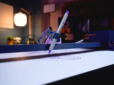
Hi friends, I previously built a mini CNC plotter that had a limited working area of approximately 100 x 100 millimeters. Additionally, the project used a custom PCB. I’ve made some improvements to this project. As requested, I set up a circuit on a breadboard featuring stepper motor drivers and an Arduino Nano. I also redesigned the X and Y axes to be interlocking.
 |  |
 |  |
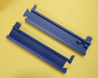
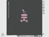
The biggest change is the size. This new version has a working area of around 400 by 400 millimeters. But my printer, the Bambu Lab A1, only supports up to 256 by 256 millimeters. So I used the cut tool in Bambu Studio. So I used the cut tool in Bambu Studio. I selected the dovetail mode and adjusted the rotation settings. Then I fine-tuned depth, width, and flap angle before placing the cut. After that, I used the perform cut option to split the model. Now the axis is divided into two parts. I temporarily removed one part and exported the other as an STL file. Then I brought back the removed part. I exported it separately as another STL file. This way, both parts are ready for printing.
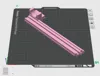
For print settings, I focused on quality. Smooth surfaces are important for the gear rails to move freely. That’s why I used higher quality settings. I also set wall loops to 3. This makes the outer walls stronger, especially at the connection points. Thin walls could cause weakness in split areas. I applied the same cutting process to the gear rail parts. These are the most sensitive components of both axes. So I recommend using careful cut and print settings here. After exporting all parts separately, we can move on to printing.
 |  |
 |  |
Once all parts are printed, we start with cleaning. Remove the supports carefully before assembly. You can use a thin flat screwdriver for tight areas. Be careful not to damage the sliding channels. The gear rails need to move smoothly inside them. If everything is clean, we can start assembling.
 |  |
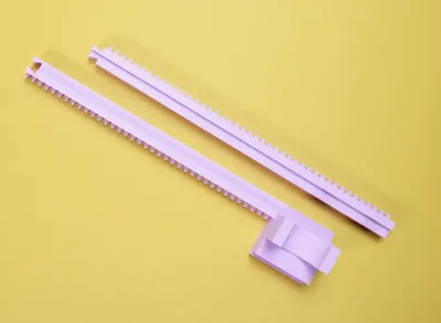
Assembly is simple and fun, just like building blocks. First, connect the split parts of the Y-axis slider. Make sure everything fits tightly. Then assemble the Y-axis gear rail parts. I made the fit slightly tight, so you may need to apply some pressure. Both parts should connect fully and move smoothly.
Next, assemble the X-axis components. Insert the gear rail and slider parts together. At this point, both axes are almost ready.
 |  |
 |  |
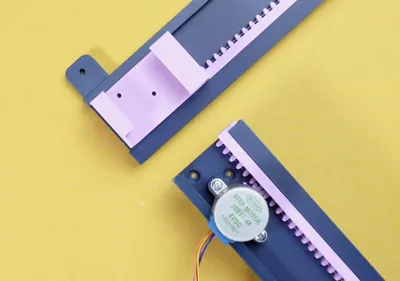
Now let’s install the motors. This project uses 5-volt hobby stepper motors with an Arduino Nano. Start by attaching the 3D-printed gears to the motors.
 |  |
 |  |
Then mount the motors onto the X and Y axes. Align the gear rails properly before placing them. Secure everything using M3 screws.
 |  |
Since the X-axis sits on the Y-axis, we need support for the free end. So I added a wheel-like support part. Assemble this support piece and attach it to the X-axis. Fix it with screws to ensure stable movement.
 |  |
Then place the X-axis onto the Y-axis frame. Secure the X-axis in place using screws.
 |  |
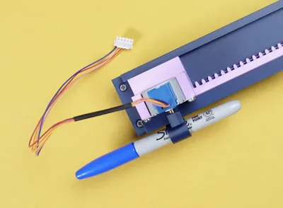
Finally, install the Z-axis motor for pen movement. Attach the pen holder to the motor shaft.
 |  |
 |  |
Now the mechanical assembly is complete. Next, let’s move on to the electronics enclosure. I designed a box that moves along with the Y-axis. The base of the box fits onto the X motor and Y gear rail. It’s designed to be easily removable. For the circuit, you’ll need a few basic components.
 |  |
 |  |
You will need an Arduino Nano, three stepper drivers, a breadboard, and some jumper wires. Follow the shared wiring diagram for connections. Also, use extension cables for the X and Y motors. Once everything is connected, we can continue.
 |  |
 |  |

Before drawing, I ran a few tests. This helped confirm the movement and working area. Everything worked as expected. Then I placed a sheet of paper on the base. I fixed it using tape from the corners. After that, I installed the pen on the Z-axis.
 |  |
 |  |
Now let’s move to the software part. First, upload the GRBL firmware to the Arduino. No changes are needed in the code.
 |  |  |
 |  |  |
Next, open Inkscape. Create a page that matches your working area. Import any image you want to draw.
 |  |
 |  |
 |  |
Convert the image into a vector. Delete the original image afterward. Then export the result as an SVG file. To generate G-code, use an online tool like JSCut. Import your SVG and set the required values. Then create the operation and generate the file.
 |  |
 |  |
Save the G-code file. Now install and open UGS software. This will control the CNC plotter. Select the correct port and connect the machine. Open the setup wizard once connected. Use the controls to test axis movement.
 |  |
Check if all axes move in the correct direction. If any axis moves backward, you can invert it in the settings. Next, position the axes to your starting point. Adjust the Z-axis so the pen is just above the paper. Then reset the machine position to zero.
 |  |
 |  |
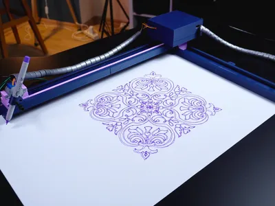
Complete the setup steps and finish the wizard. Now import your G-code file. Start the machine and observe carefully. During the first run, keep your hand near the pause button. Watch for any incorrect movement or pen issues. Be ready to stop the machine if needed.
 |  |
I noticed a small issue with the pen position. So I paused the machine and fixed it. After that, everything worked properly. Now the CNC plotter is fully ready. With fine tuning, you can get even better results. That’s something you can improve over time.
 |  |
 |  |
The main goal of this project was to show how you can go beyond the size limits of a 3D printer. By splitting large models into parts, you can build much bigger projects. This technique opens up many possibilities. I hope this video was helpful for you. Feel free to ask your questions in the comments. Thanks for reading, and see you in the next project!
Required Software Links:
- GRBL Firmware - https://github.com/TGit-Tech/GRBL-28byj-48
- Inkscape - https://inkscape.org/release/inkscape-1.0.1/
- Convert your SVG files - https://jscut.org/
- UGS Platform - https://winder.github.io/ugs_website/download/
Y-Axis Gear Update and Fit Improvement
Various improvements have been made in response to user feedback regarding issues with the Y-axis gear getting stuck inside the rail and problems with the dovetail connection. The contact surfaces of the Y-axis gear, which slides inside the rail, have been slightly reduced in size to ensure a smoother and more reliable fit. If you are still experiencing jamming issues, it is recommended that you lightly sand the contact areas to help the gear seat properly or move the gear back and forth a few times.
 |
 |  |
This issue typically arises due to printing tolerances such as excessive extrusion (flow rate), minor warping during printing, filament variations, or overall print quality. Even small differences can create internal pressure between separate parts, which may cause warping or improper seating in the dovetail joint.
As a result of these adjustments, the Y-axis gear was re-machined using the Bambu Studio Cut tool, and the dovetail joint was redesigned to meet the updated tolerances. Additionally, full (undivided) STL files are now included for all axes; this allows users to perform the slicing process themselves if they wish.
Boost Me (for free)
Like this model? 🚀 I’m a maker who loves building and experimenting with new ideas. Your boost helps me keep creating and sharing more — thank you! 😇
🙏 Thanks for checking out my model! 💬 Let me know your thoughts in the comments!
⭐ If you like it, don’t forget to like and follow for more designs
🎥 YouTube: @maker101io (170K+)
📱 Instagram: maker101io (44K+)
License
You shall not share, sub-license, sell, rent, host, transfer, or distribute in any way the digital or 3D printed versions of this object, nor any other derivative work of this object in its digital or physical format (including - but not limited to - remixes of this object, and hosting on other digital platforms). The objects may not be used without permission in any way whatsoever in which you charge money, or collect fees.
Comment & Rating (20)