
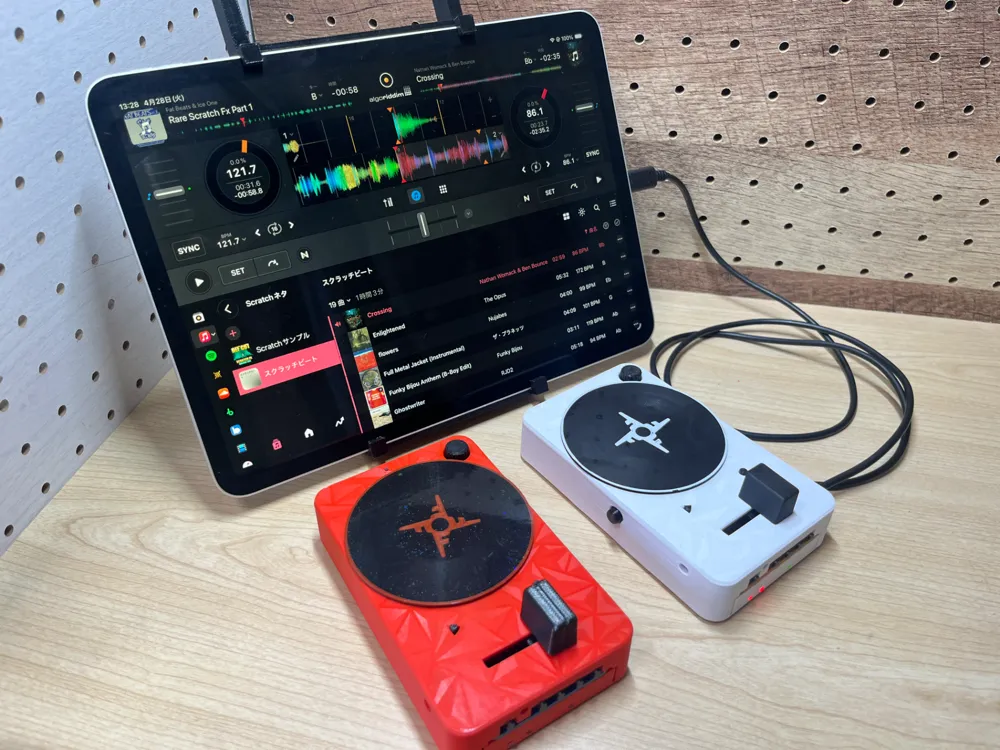
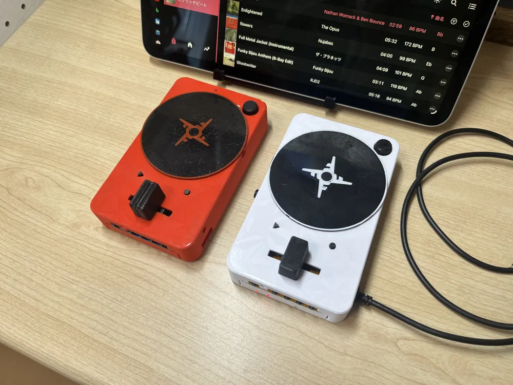
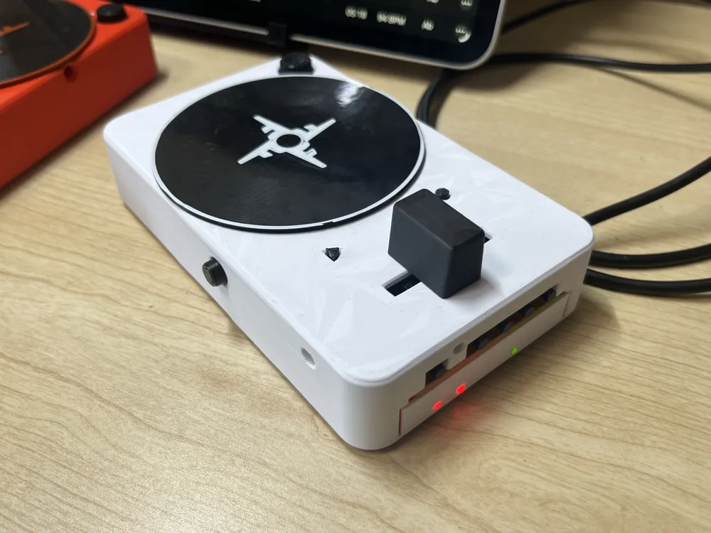
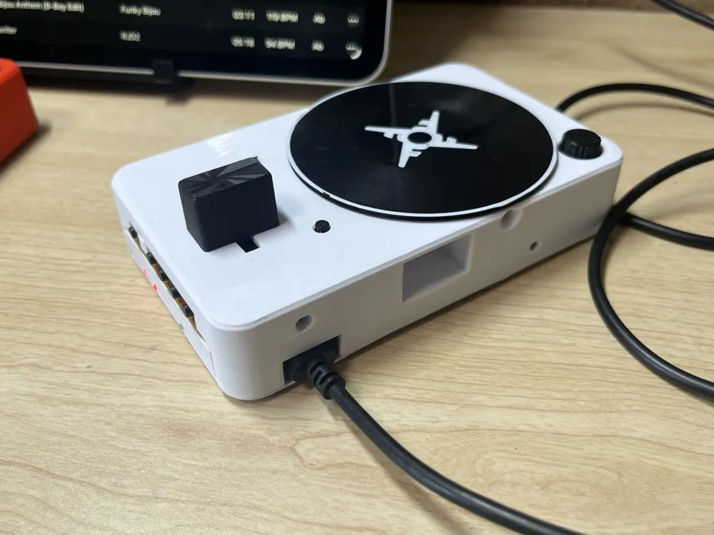
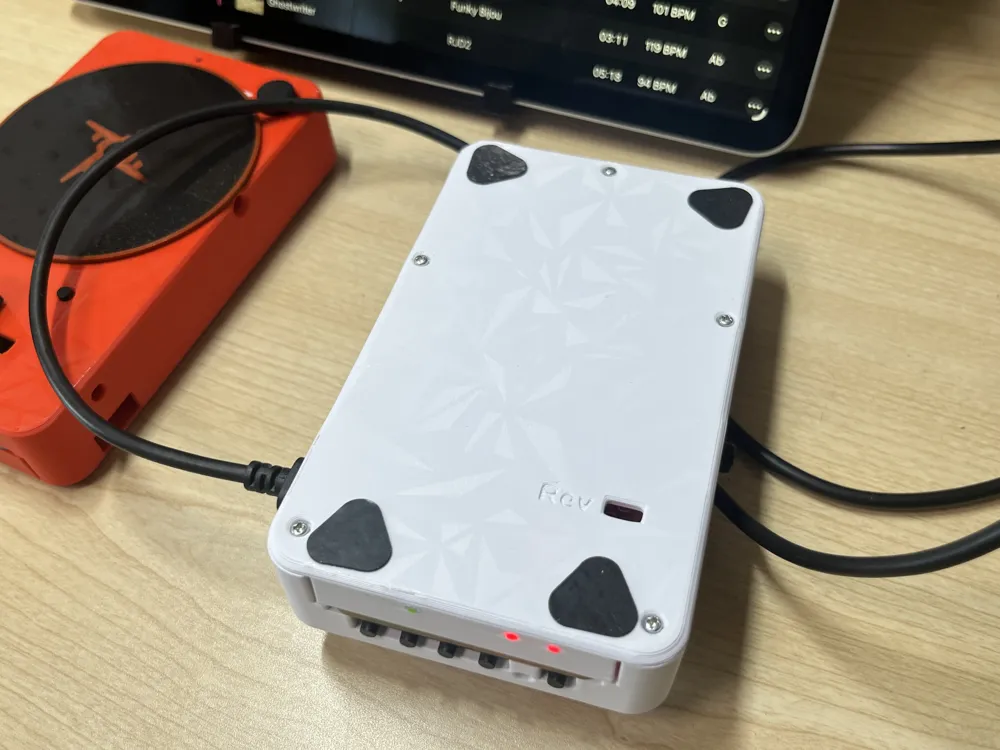
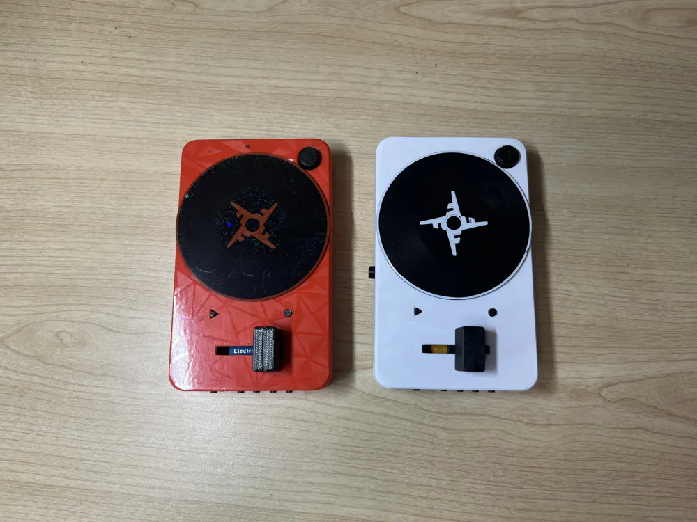
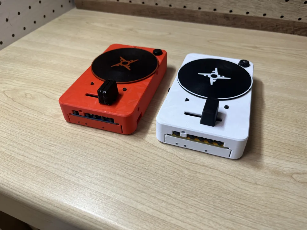
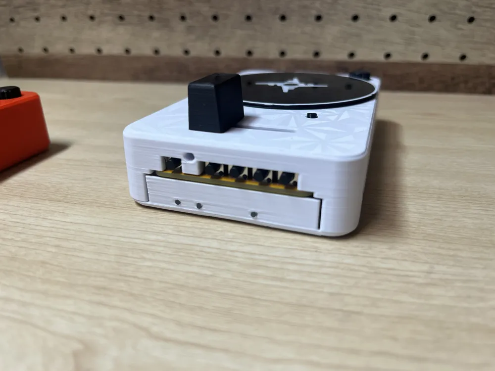
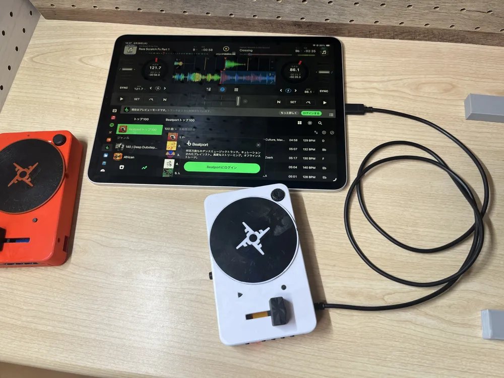
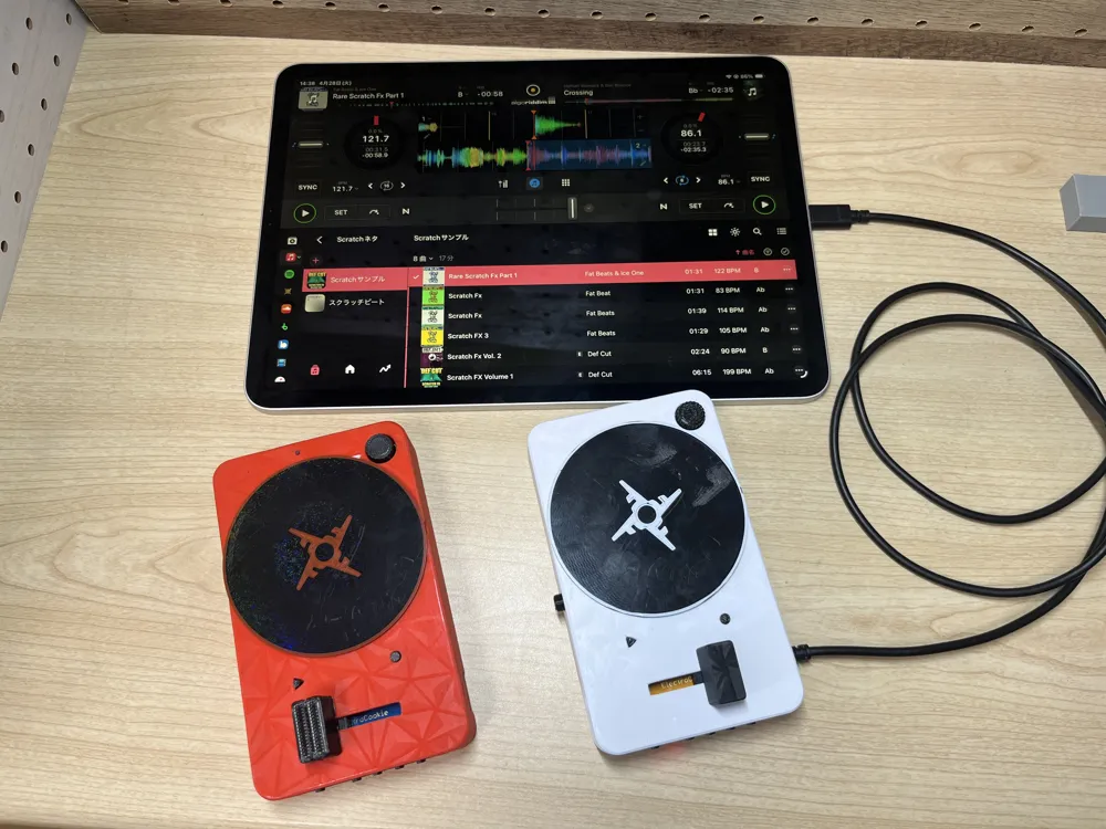
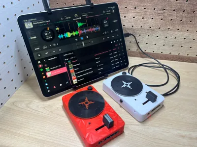
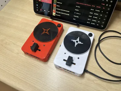
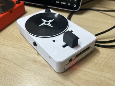
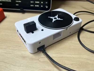
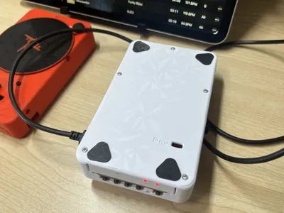
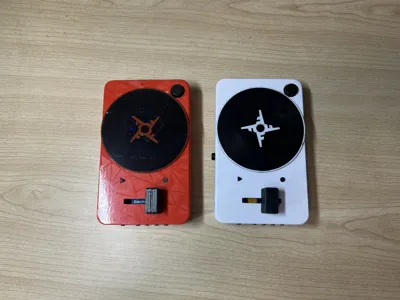
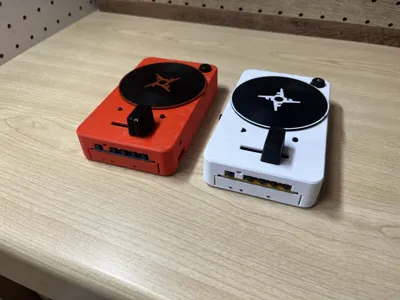
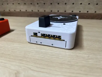
"Scratch Ninja" 3-inch platter MIDI controller for scratch DJs
Print Profile(1)
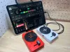
Description
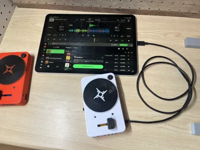
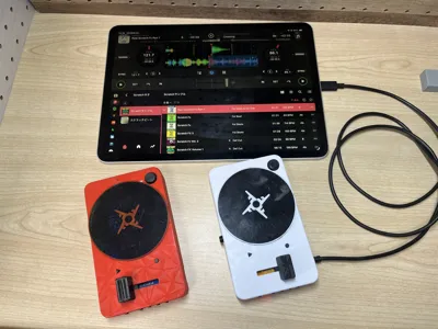
I created a MIDI controller that can be used with djay (paid subscription required)
You can practice scratching with songs in djay
Since I went to the trouble of introducing a buzzer, I also added a mode that allows scratching with the buzzer
I have no knowledge of programming
I only learned how to create 3D data while playing around
Nevertheless, it has become a good era where such equipment can be made with the help of AI
[Documents]
Documents created by AI
| File | Content |
|---|---|
| README.md | Project Overview |
| Scratch_Ninja_Final.ino | Firmware main body |
| BOM.md | Bill of Materials |
| Wiring.md | Wiring Diagram (Pin Details) |
| MIDI_Mapping.md | MIDI Settings List (djay setting example) |
| Build_Guide.md | Build Steps and Troubleshooting |
[Pre-cautions]
・A djay subscription is required
・Soldering skills are required
・Operation has only been confirmed on iPad and iPhone
・Feel free to create one for personal use
・If you wish to sell it, it will be after a commercial license is acquired
(Please follow me, etc.)
・Feel free to modify the data, etc
・Program data, etc., were created by AI
____________________________________
[Table of Contents]
・Output 3D printed parts
・Assembly
・Assemble the circuit board
・Write program to Arduino Pro Micro
・Load djay mapping file
・Required parts
____________________________________
[Output 3D printed parts]
※-The platter part must be made with conductive PLA
____________________________________
[Assembly]
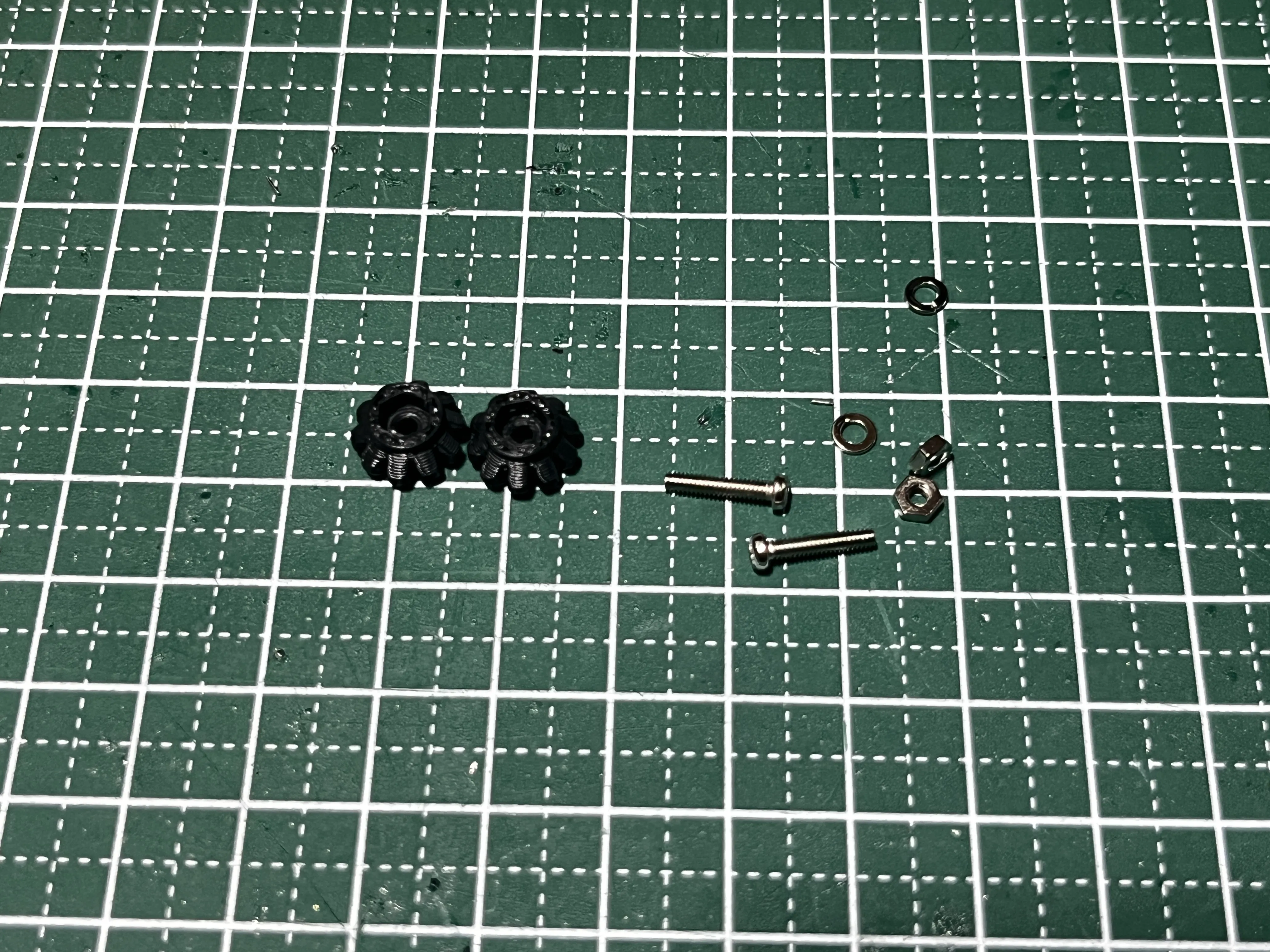
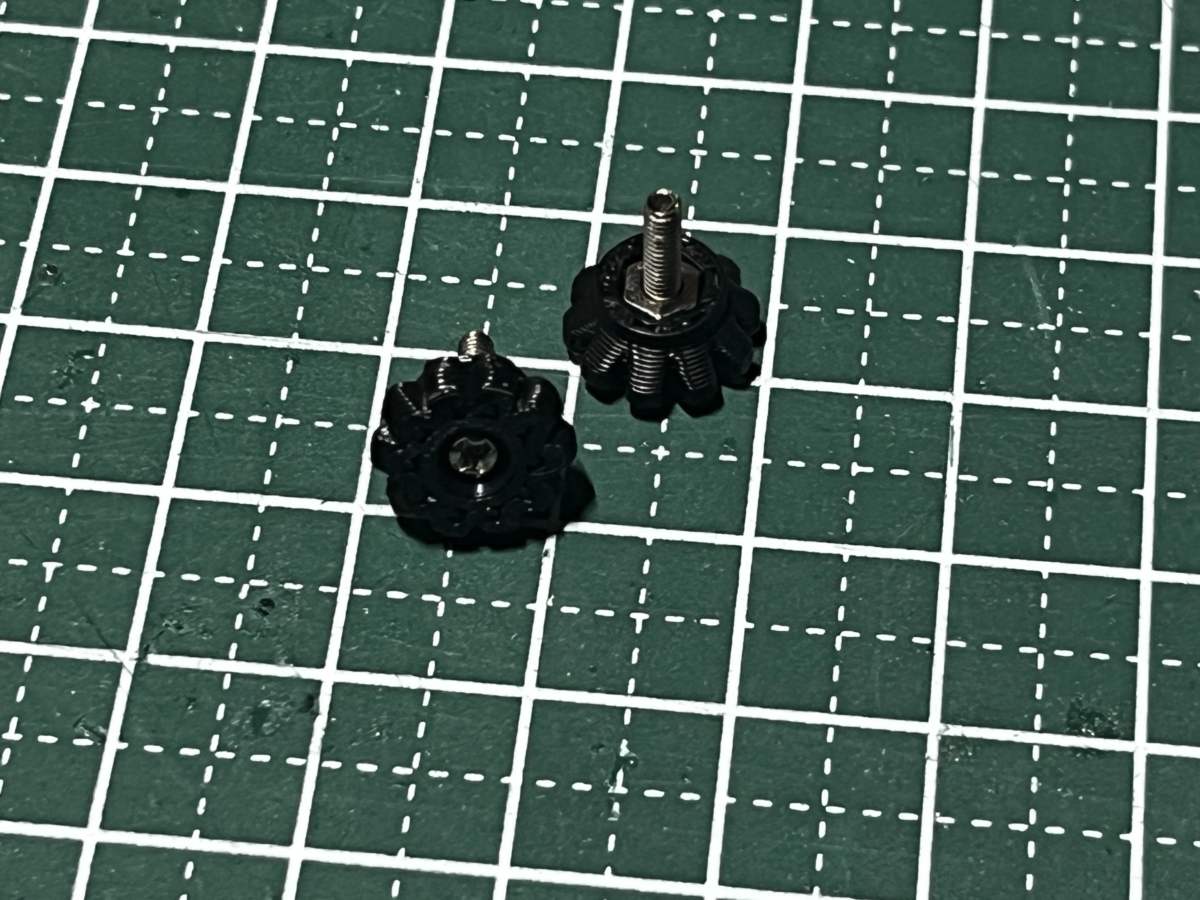
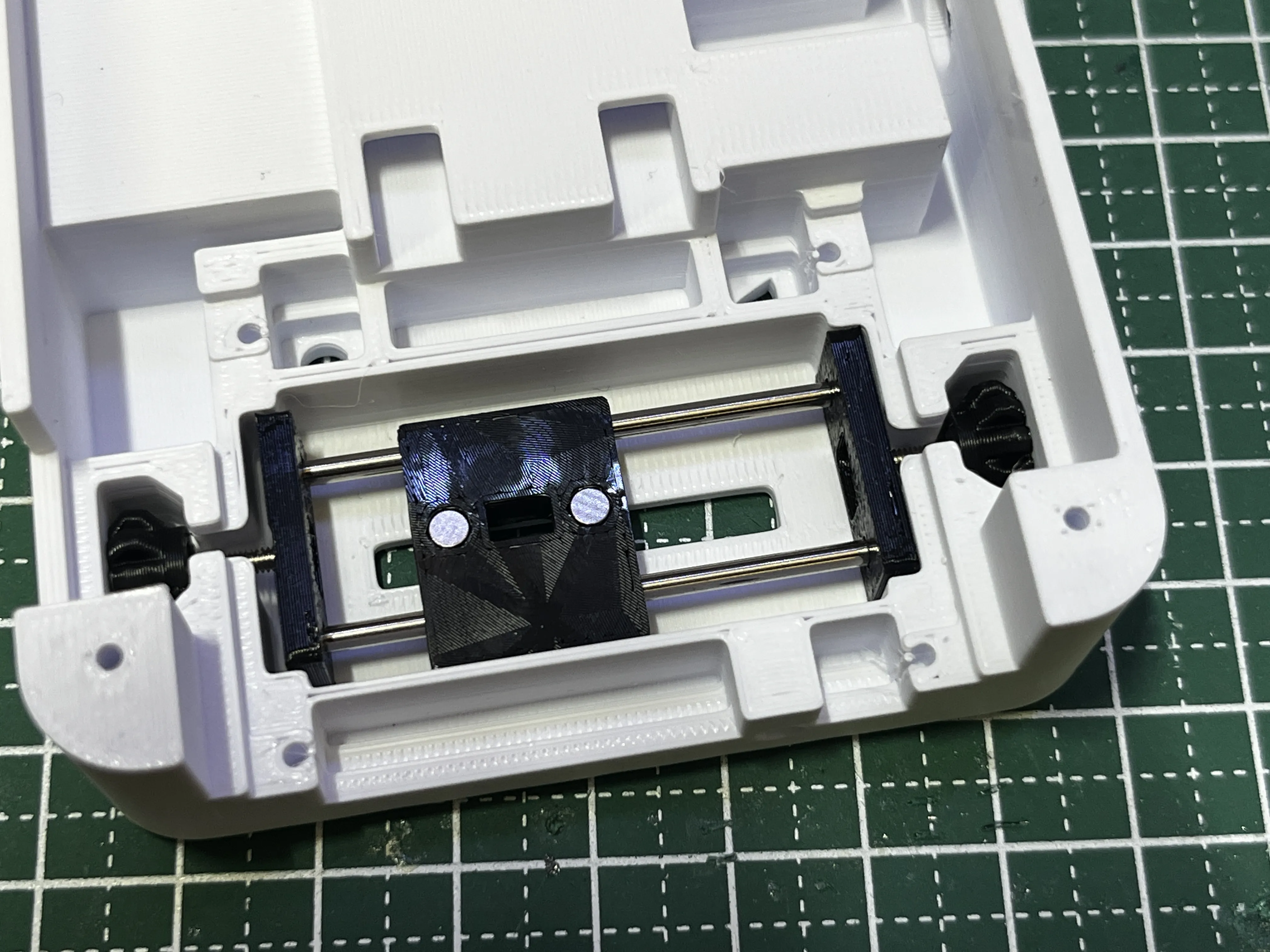
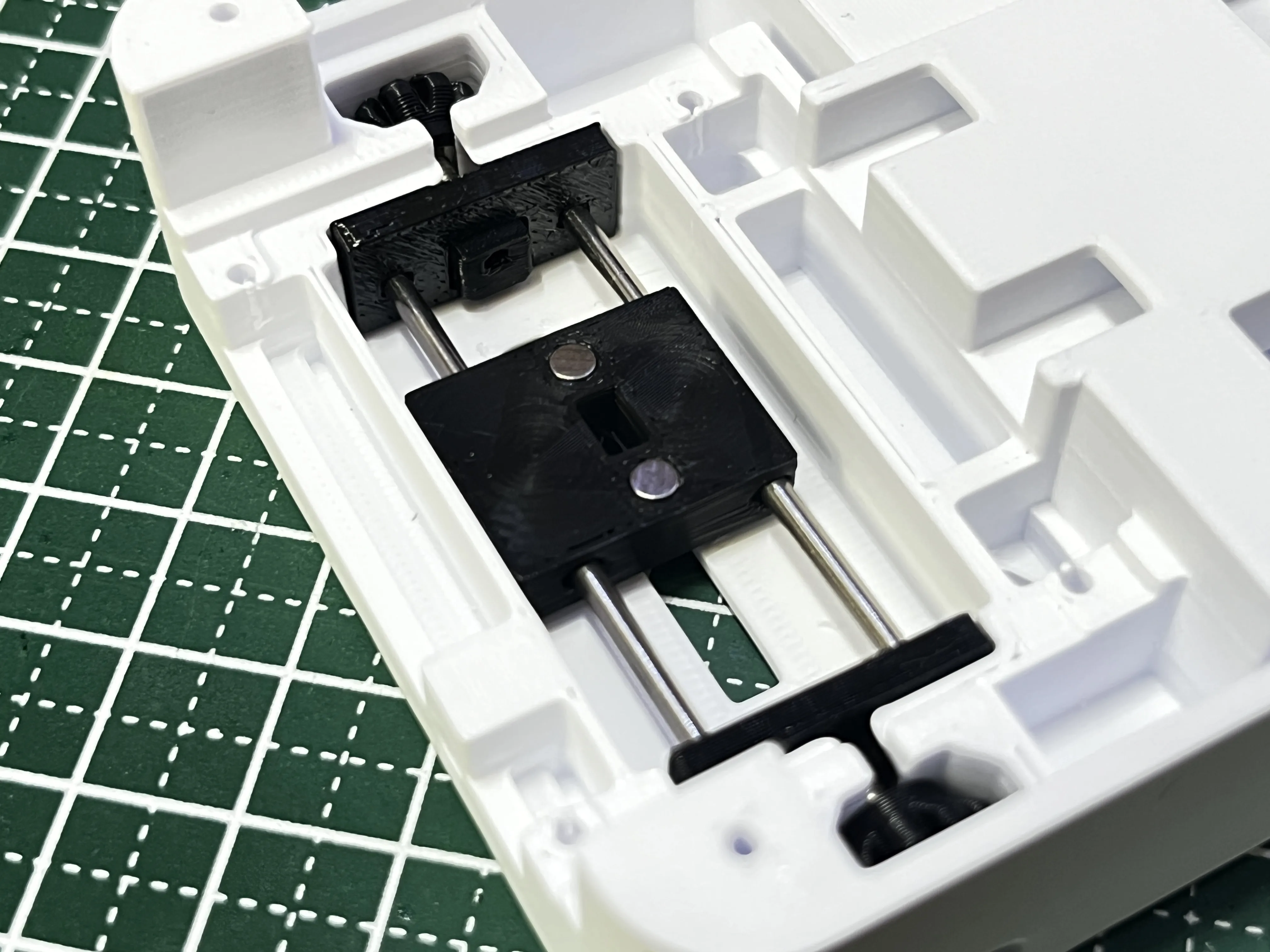
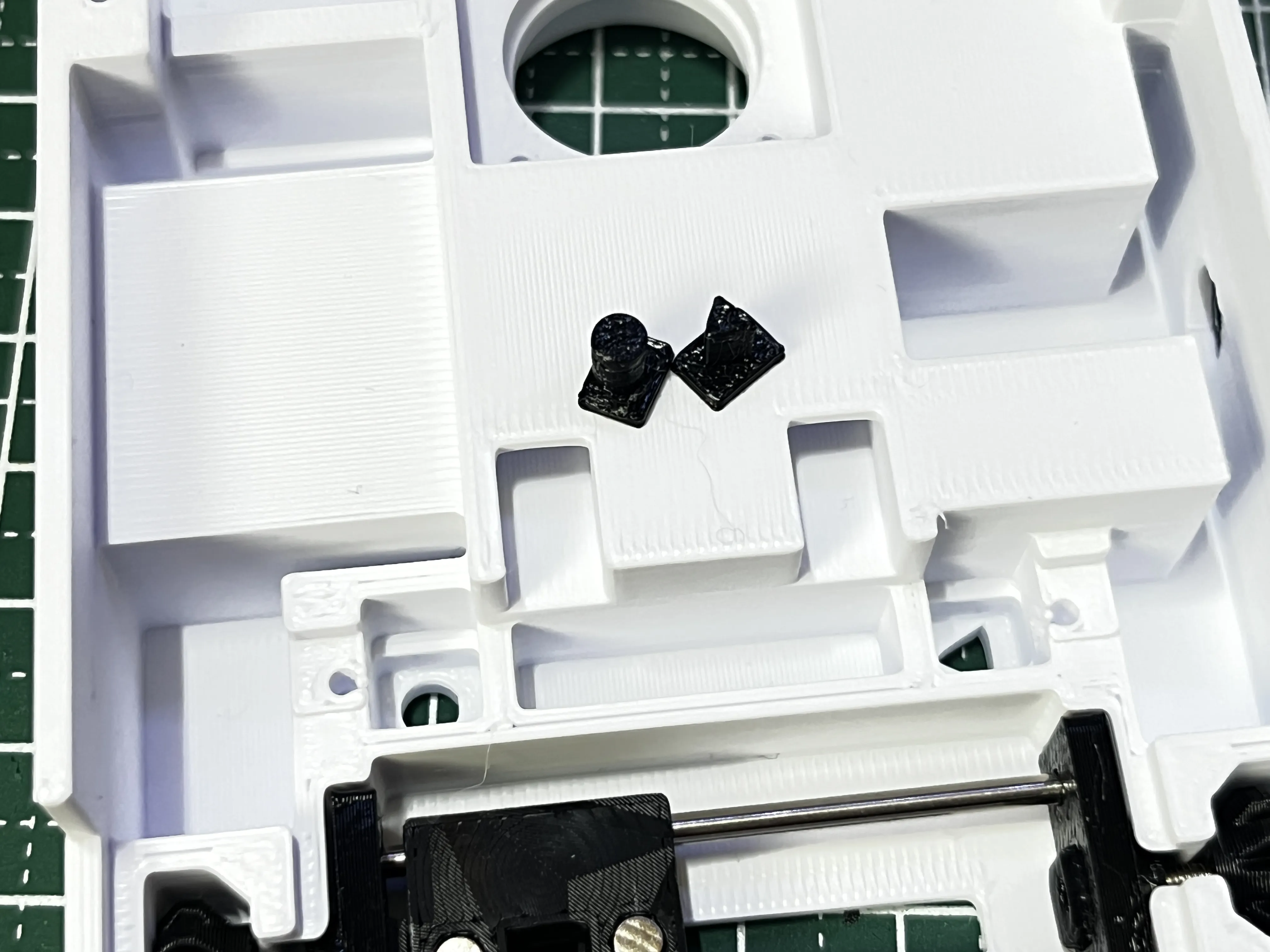
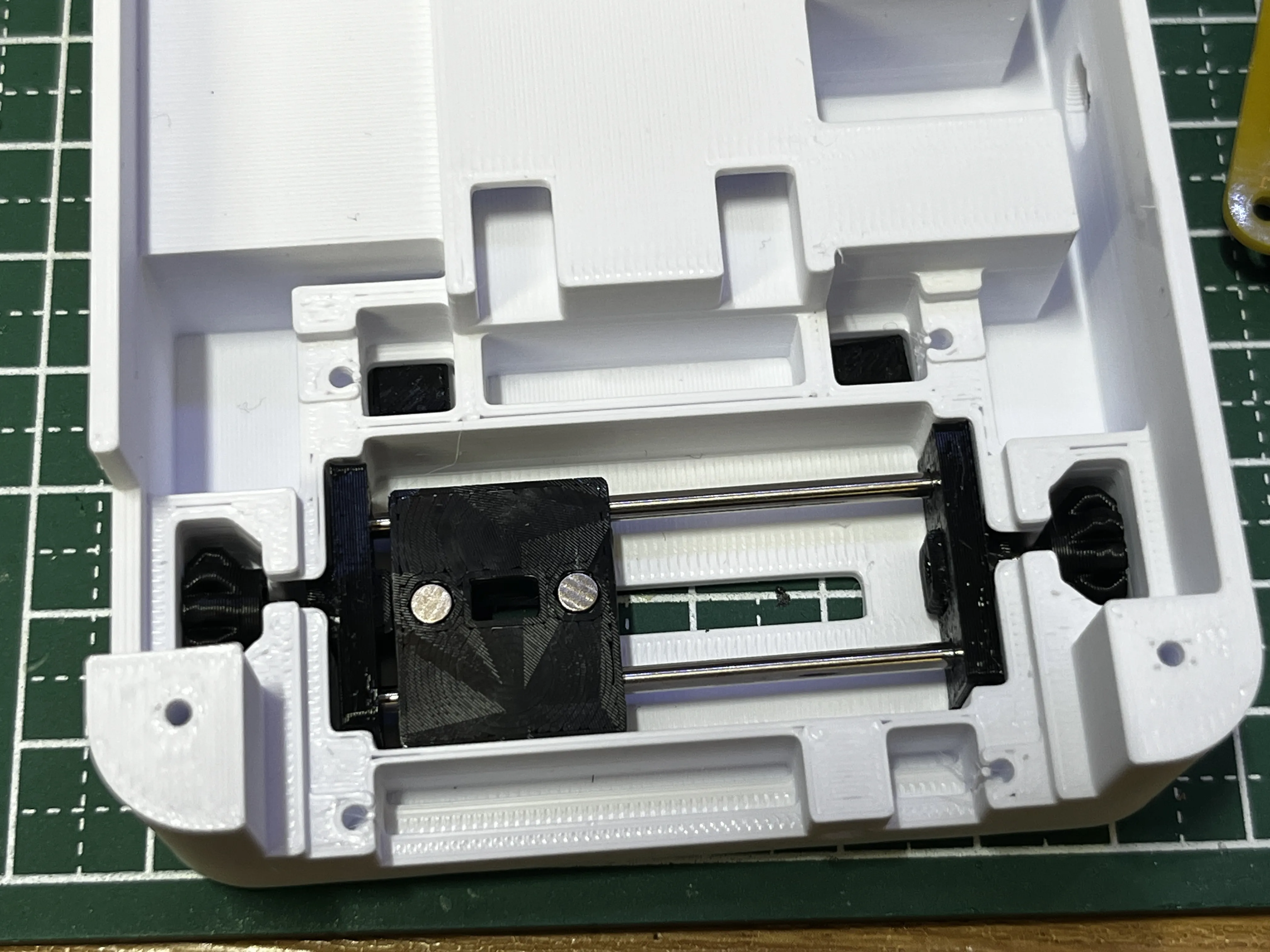
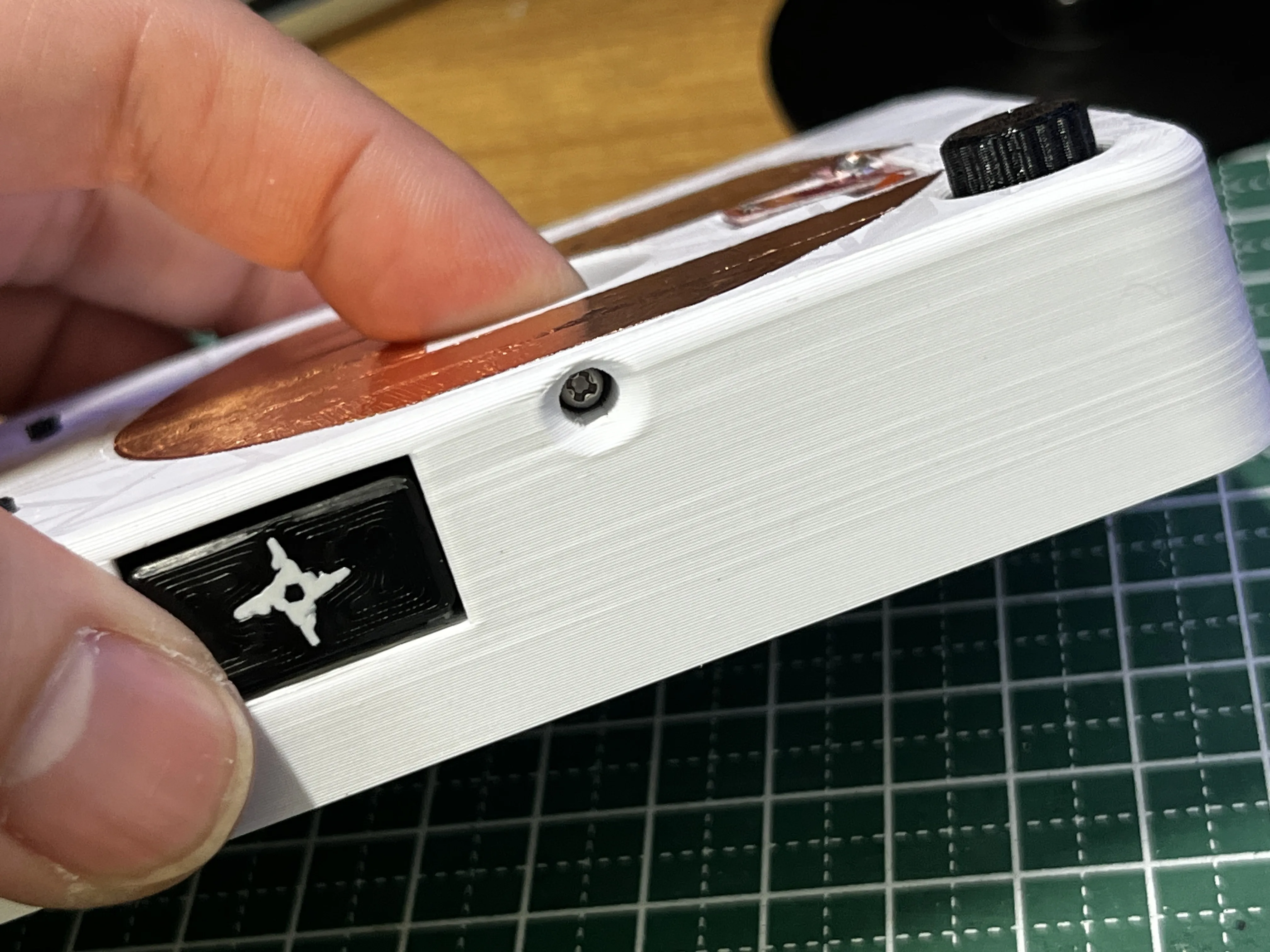
Create and install screws for cut lag adjustment (screws should be about M2 x 10mm)
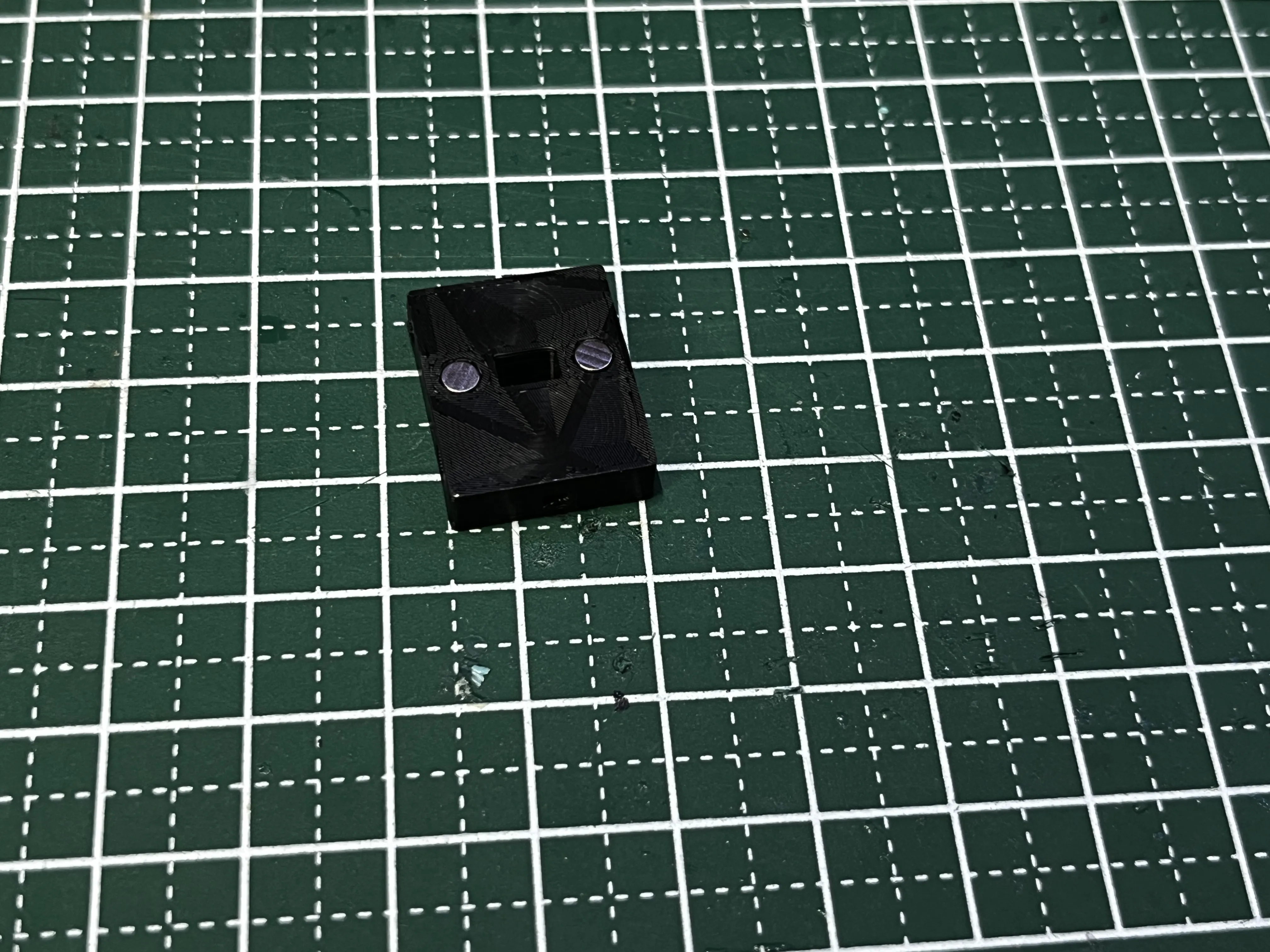
Attach a magnet to the bottom of the fader M3 x 2mm
If you need to adjust the fader weight, prepare this
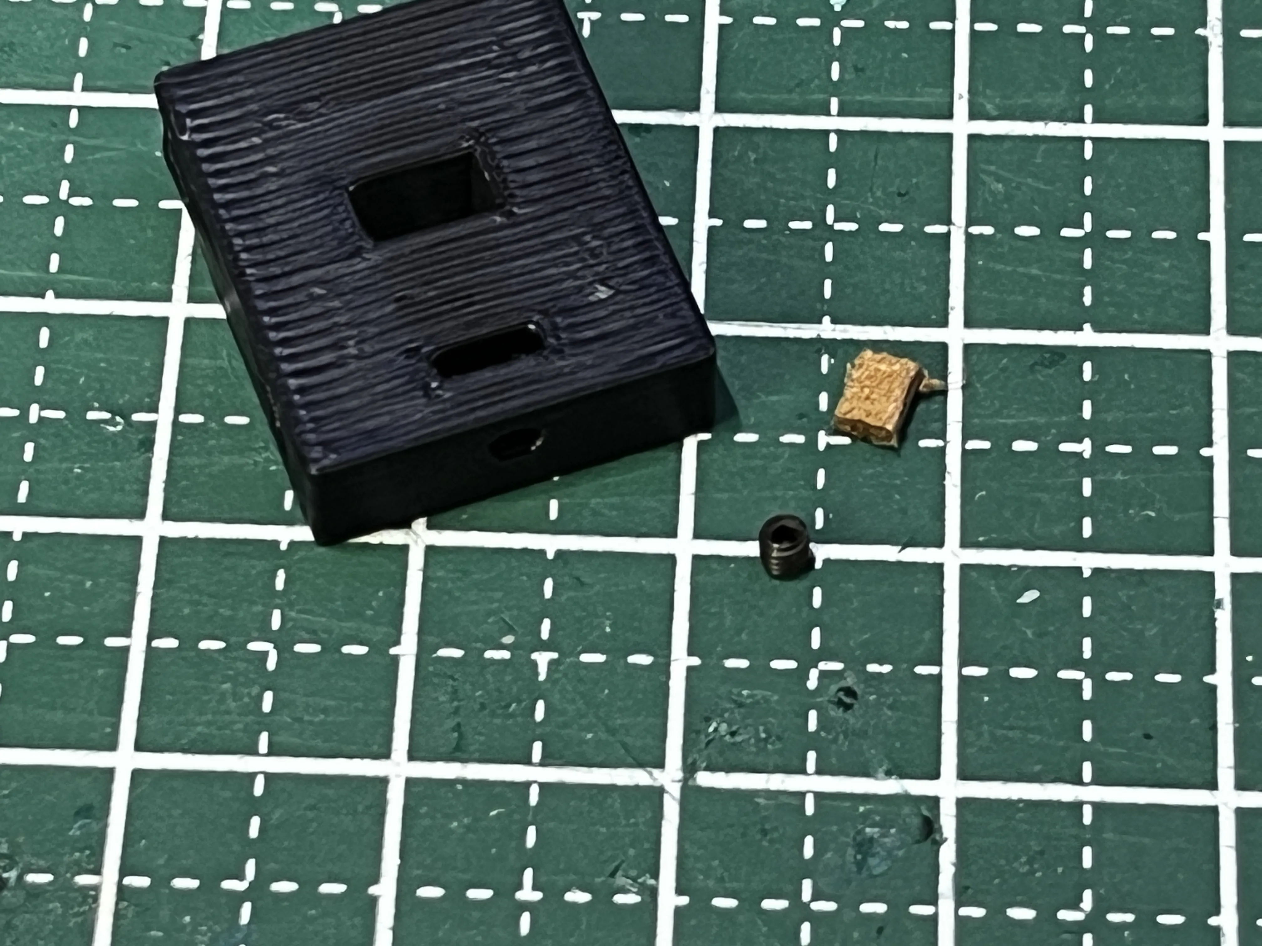
If you dislike it being too slippery, insert fake leather or similar as a non-slip material and install an M2 x 2mm grub screw for sensitivity adjustment
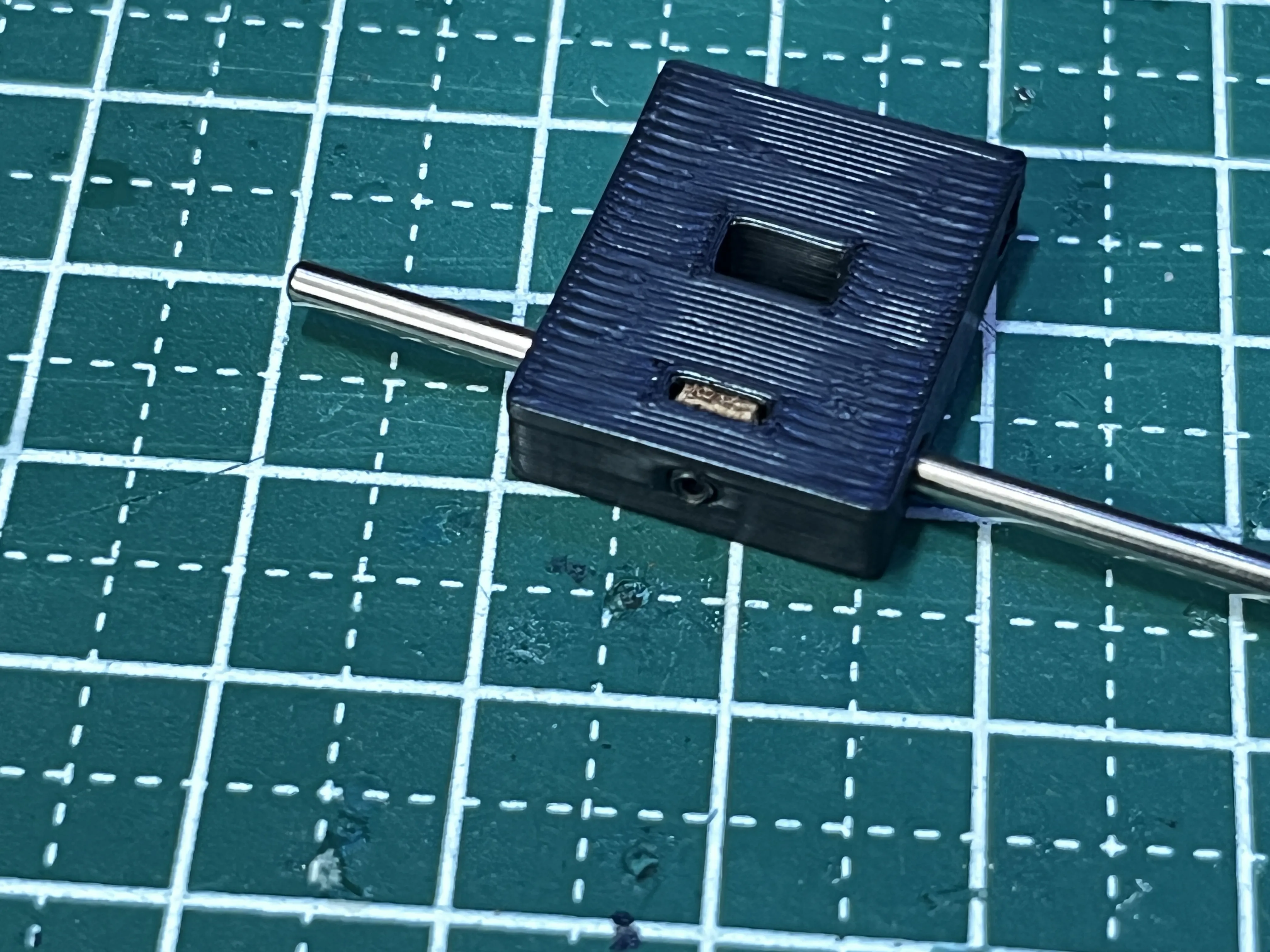
Fix using the side blocks
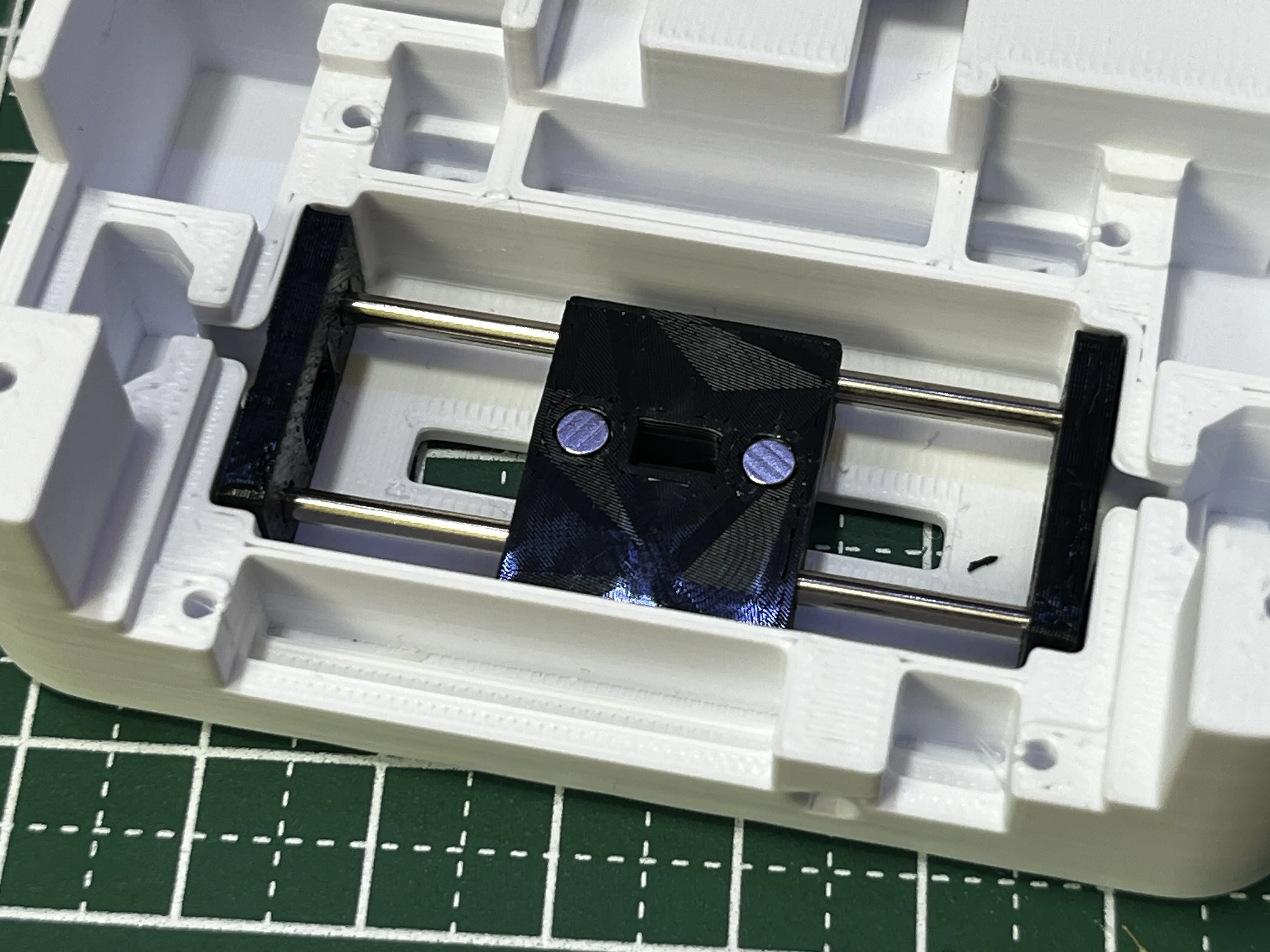
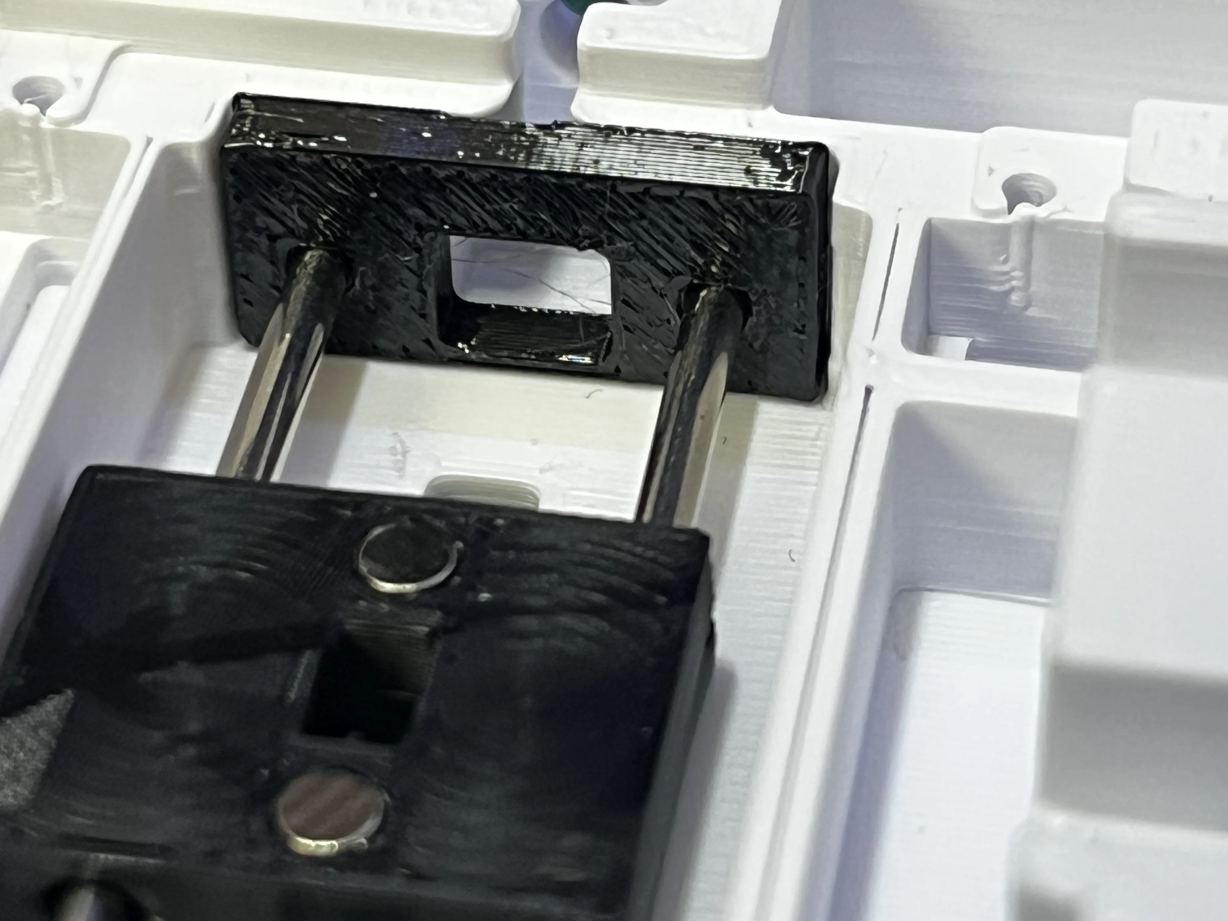
Install the cut lag adjustment screw
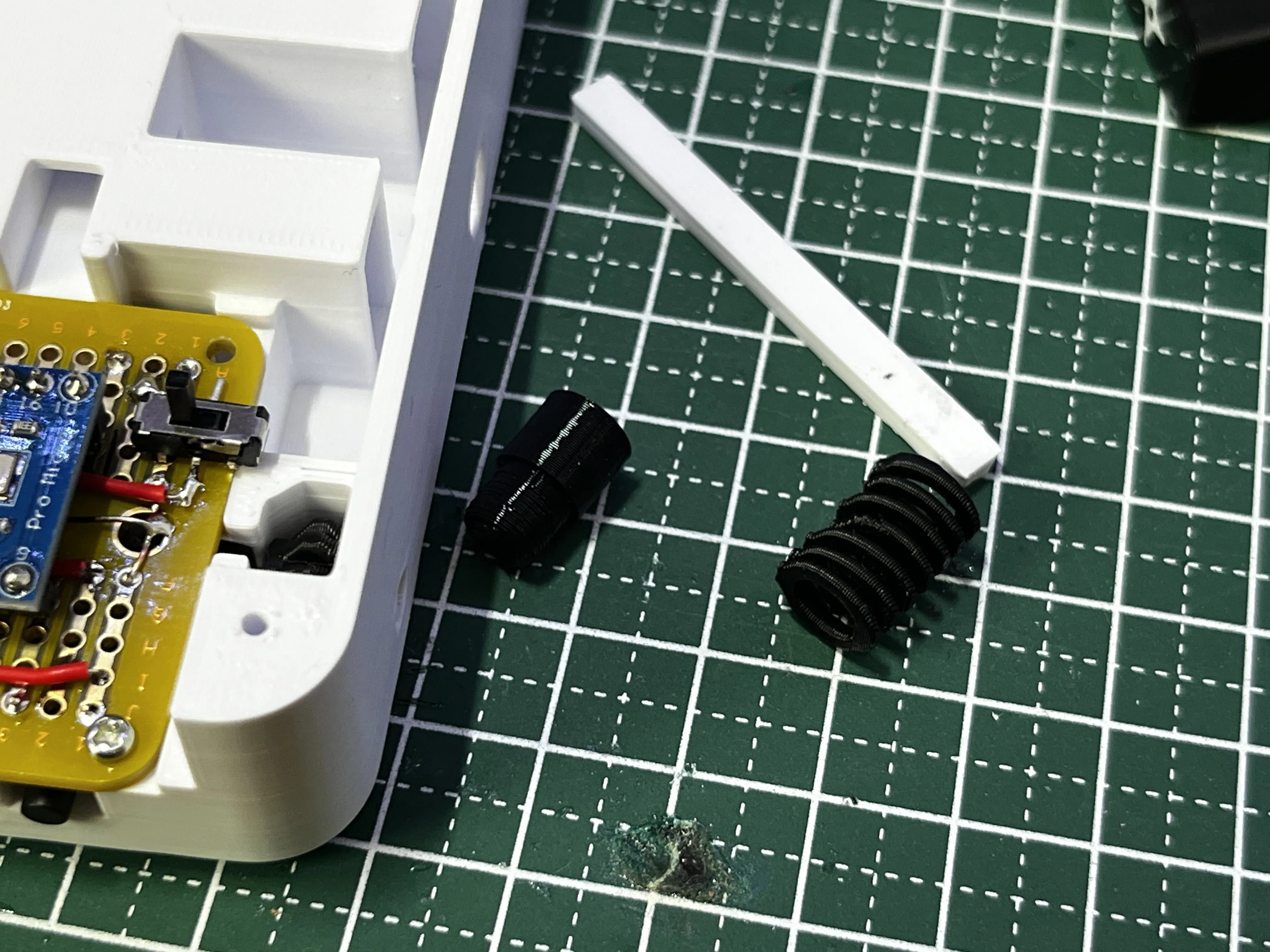
Create shuriken throwing parts
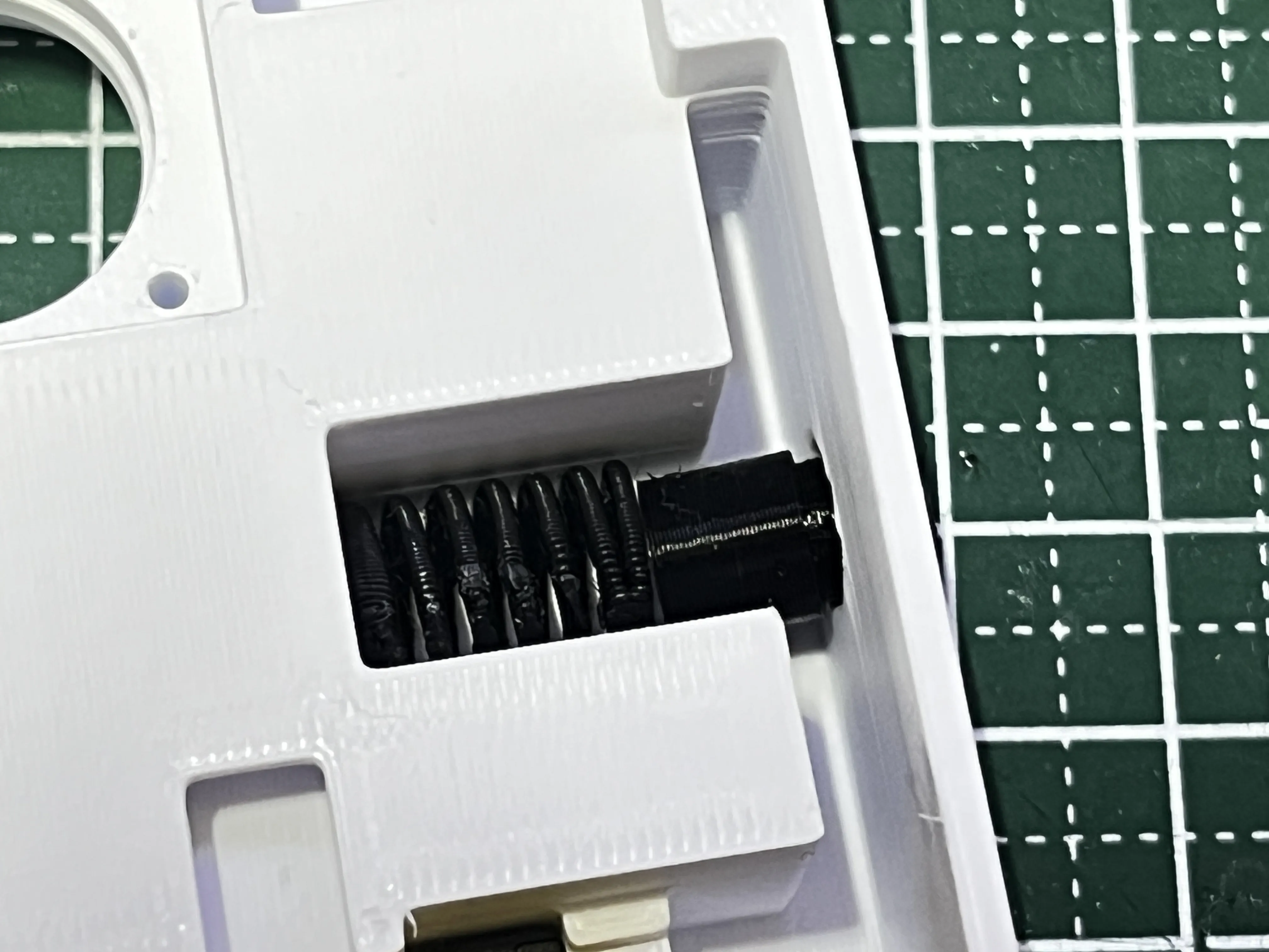
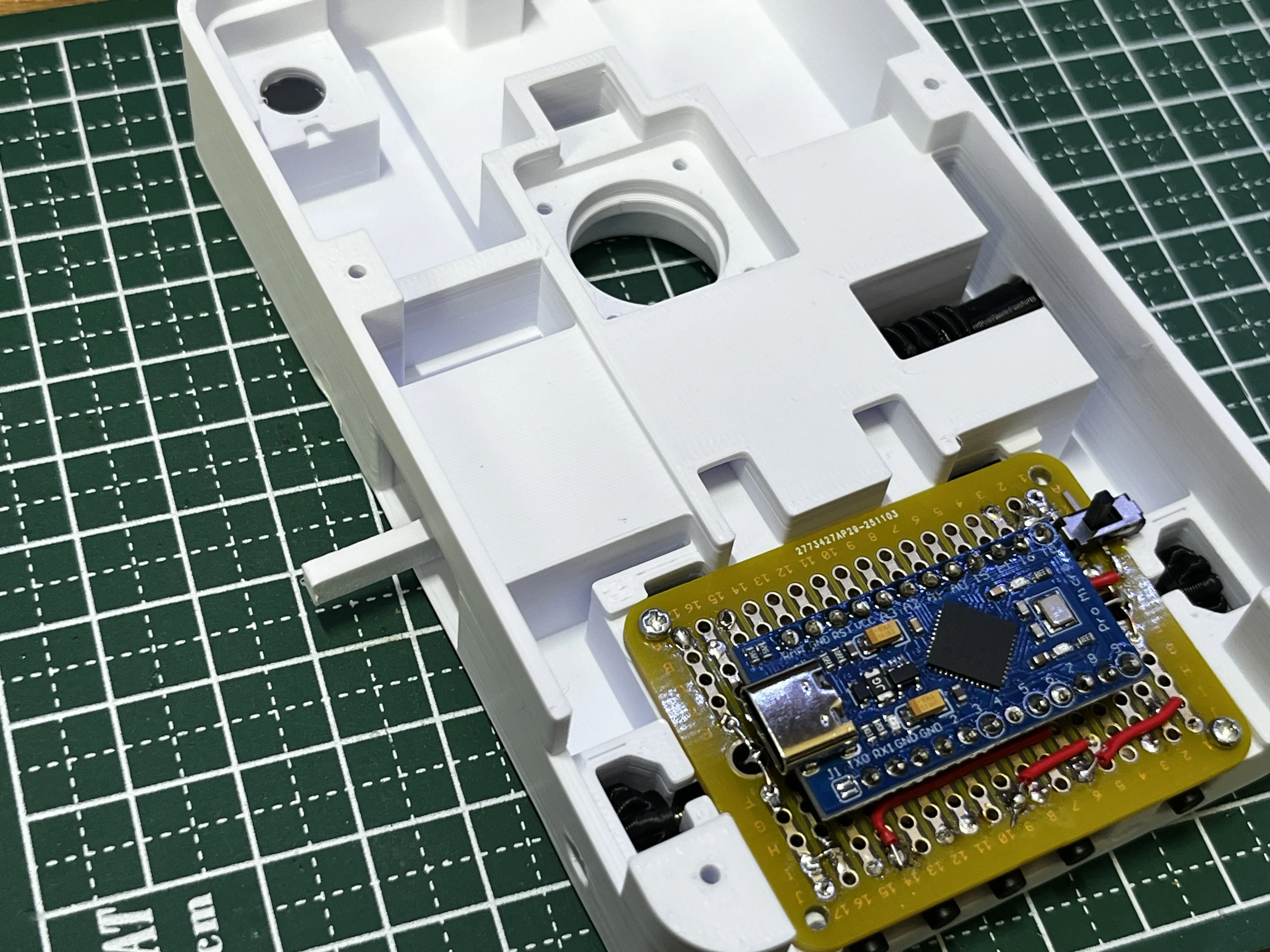
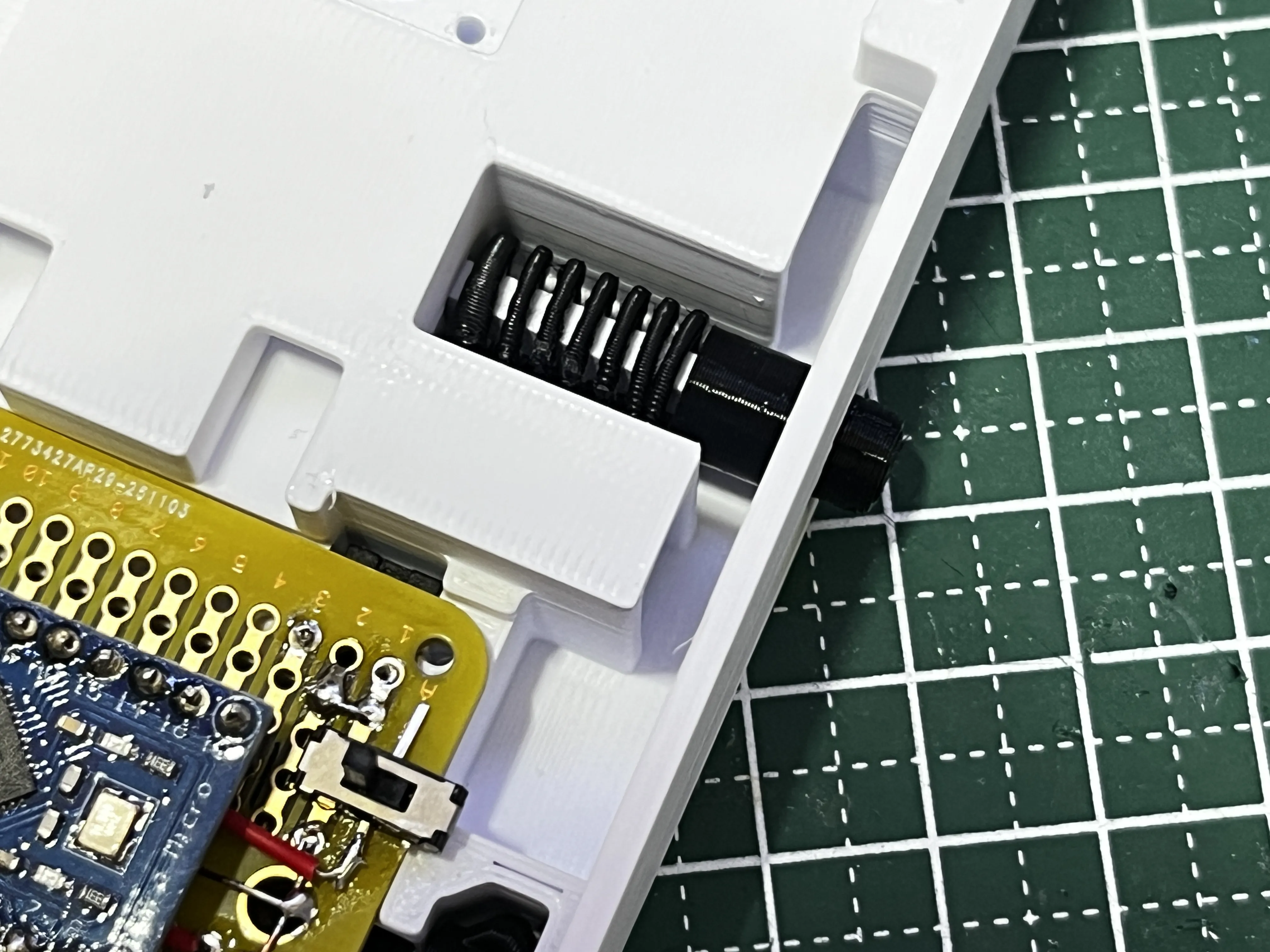
If it comes off easily, secure it with adhesive
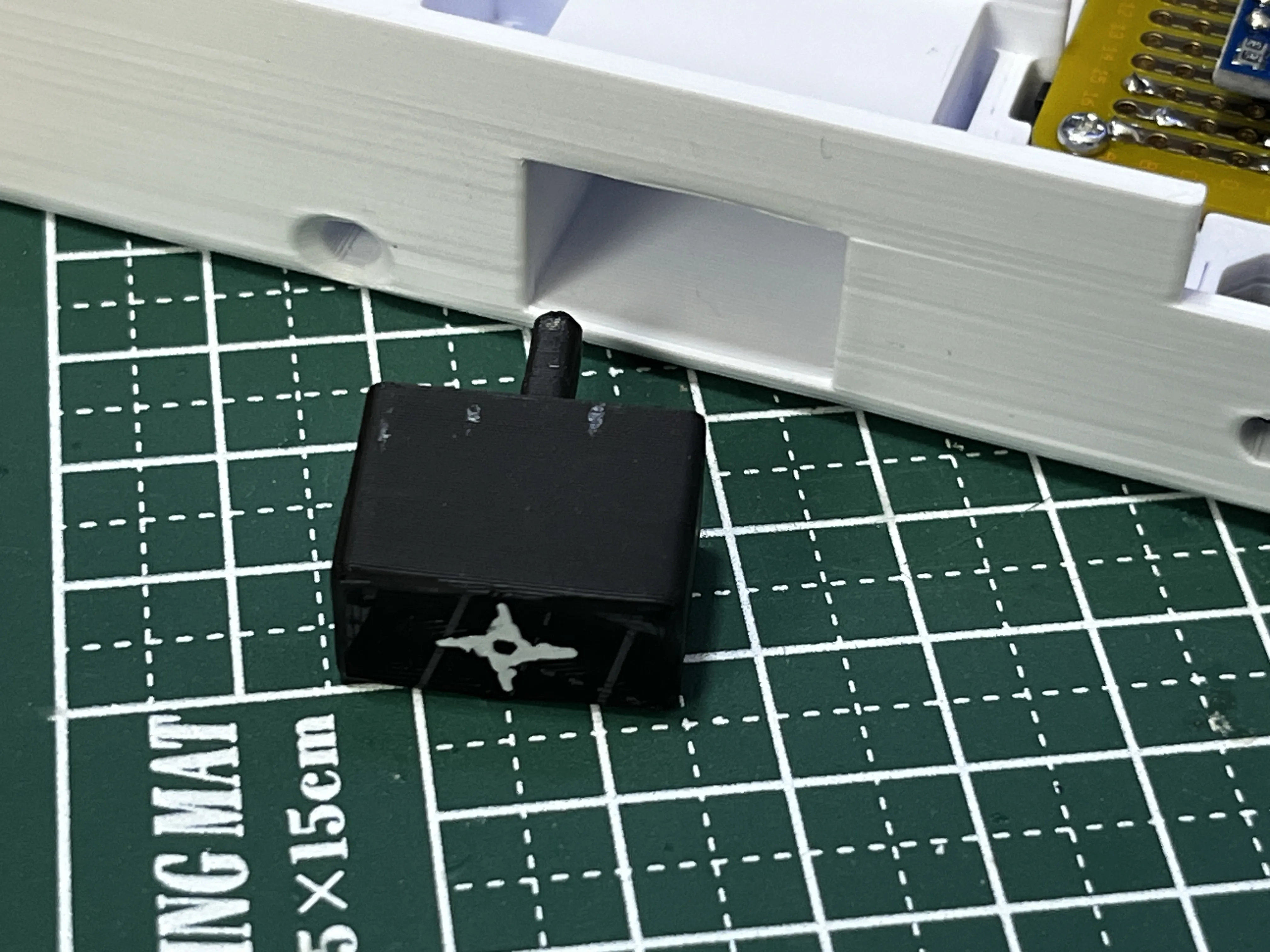
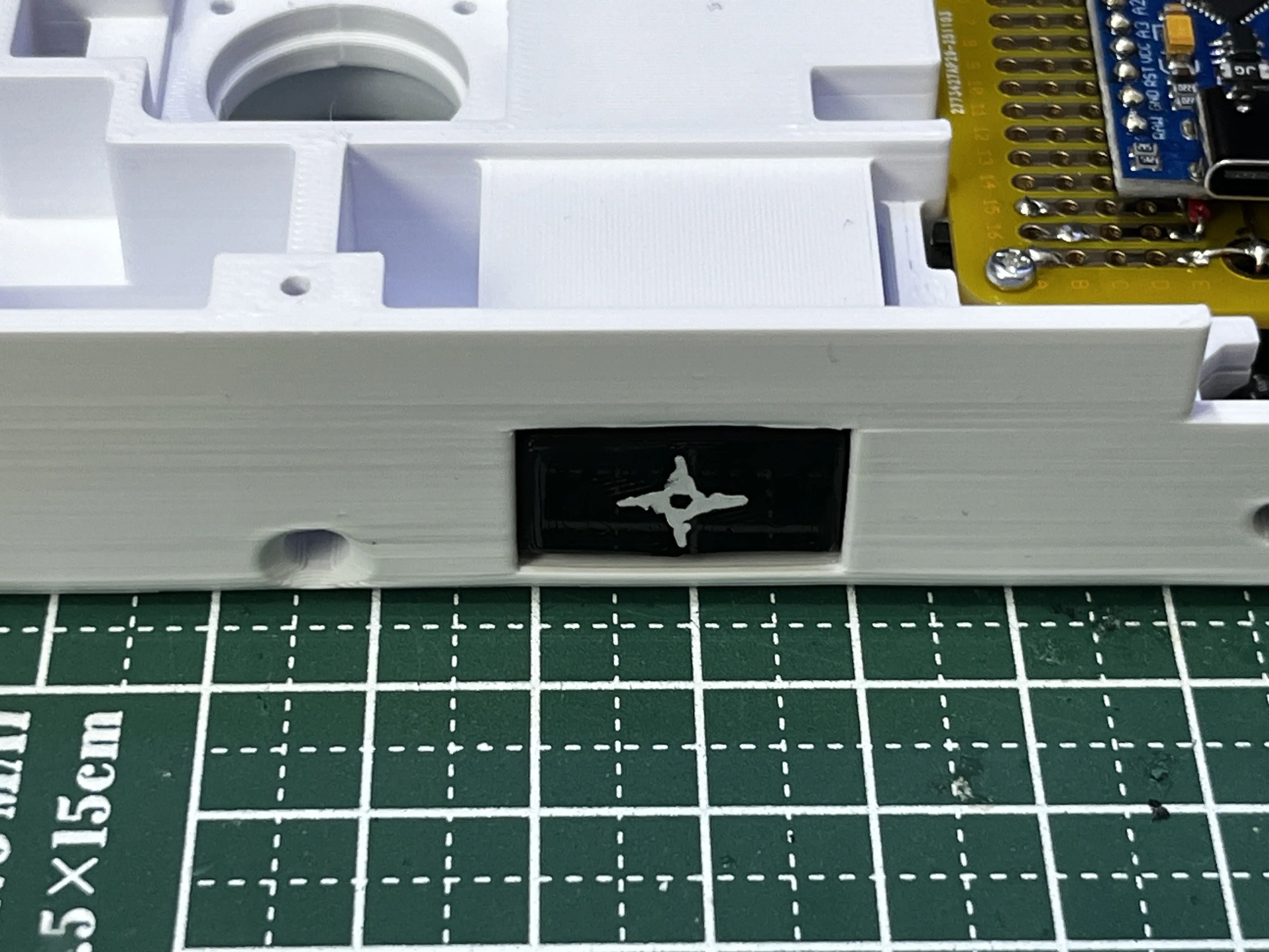
If you press the button and it pops out, it's OK
Install playback buttons, etc
____________________________________
[Assemble the circuit board]
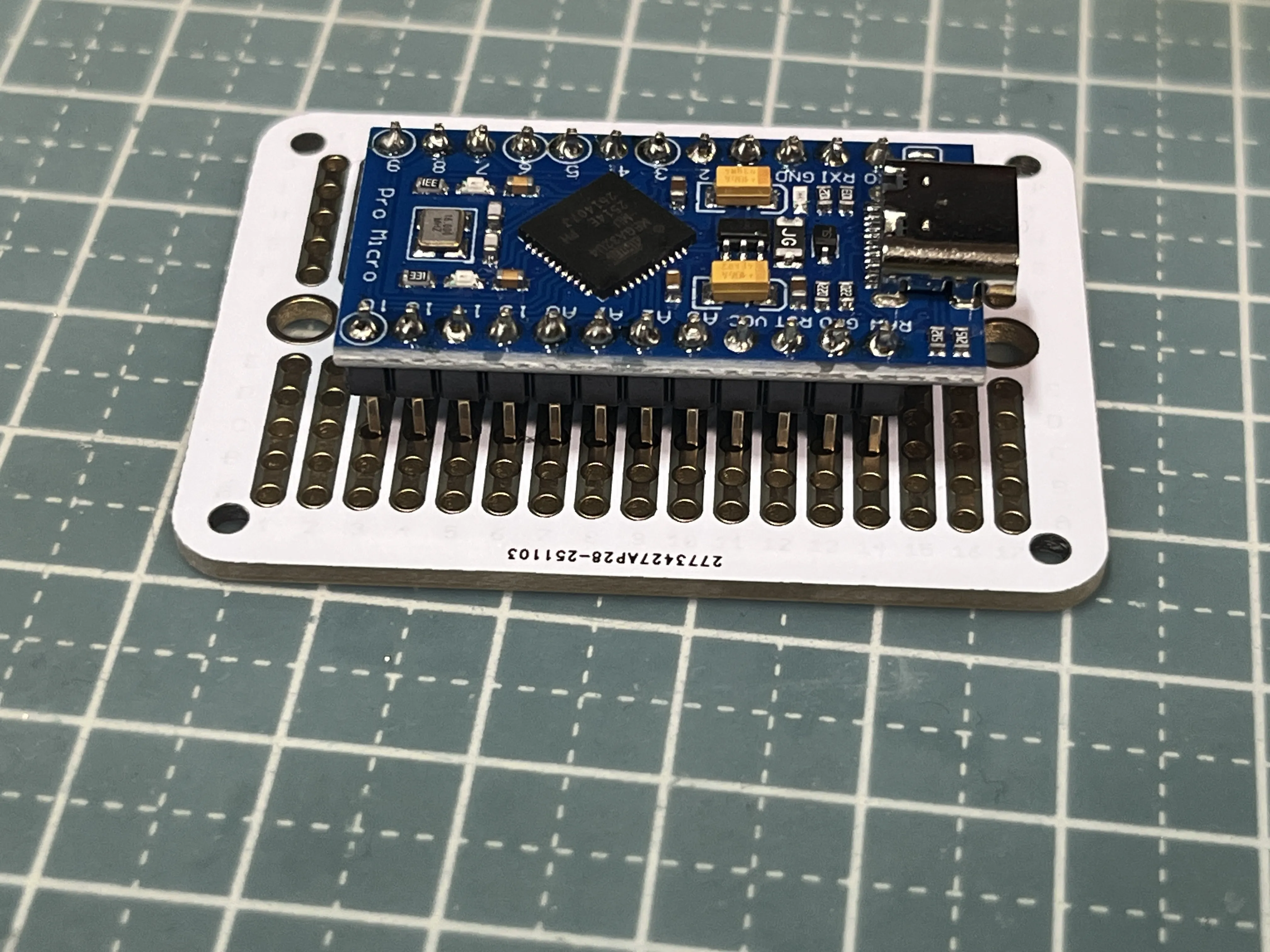
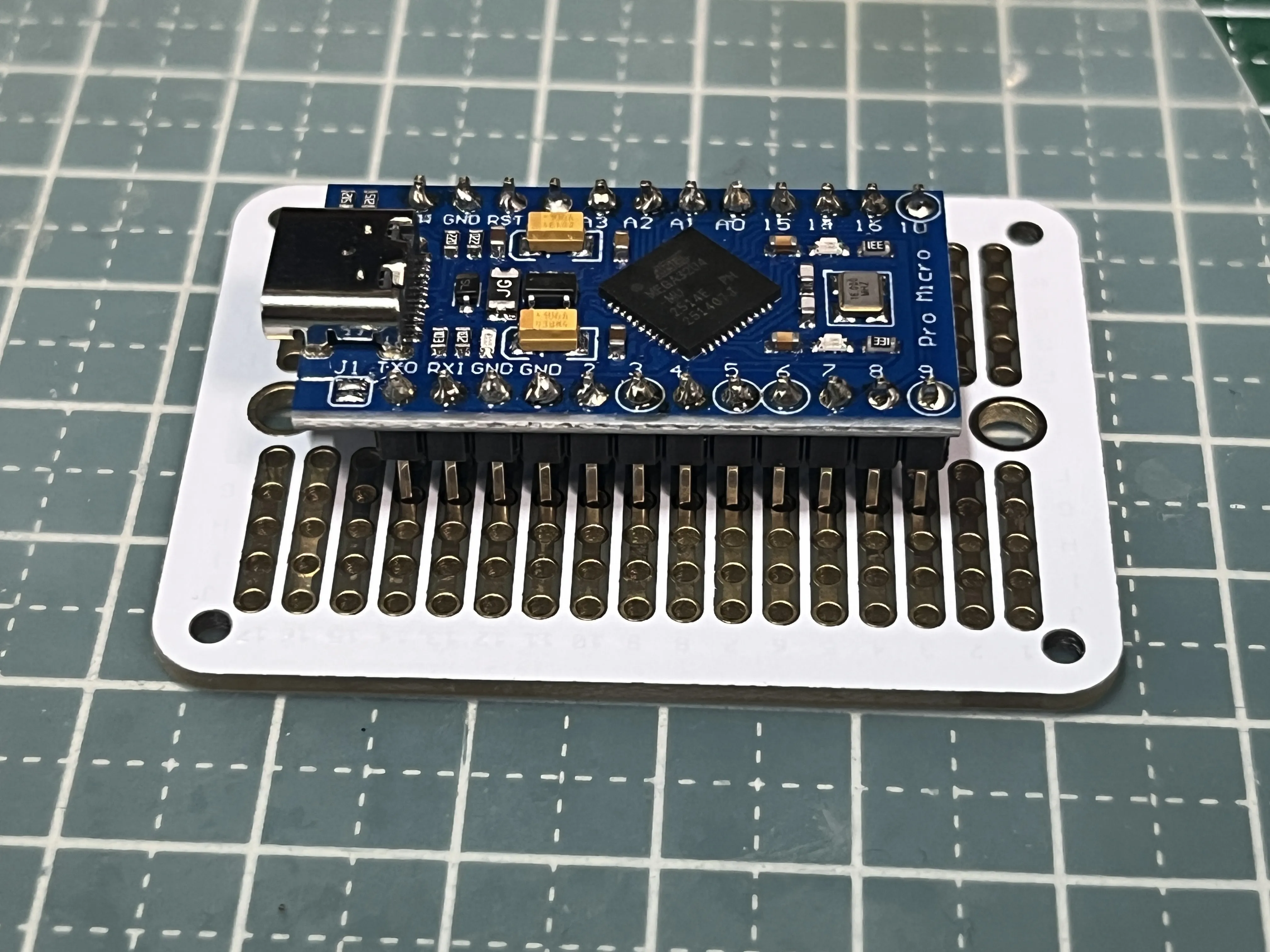
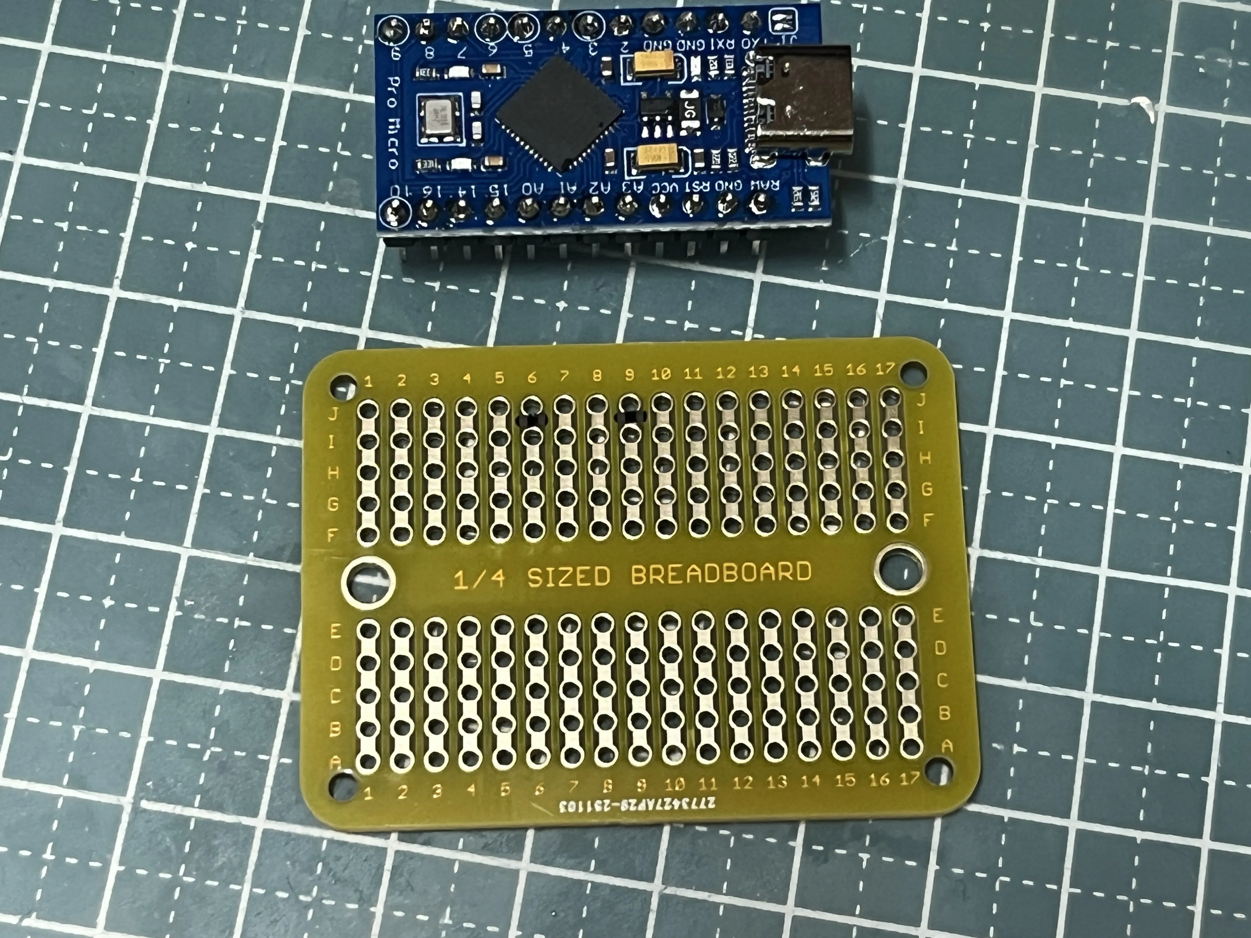
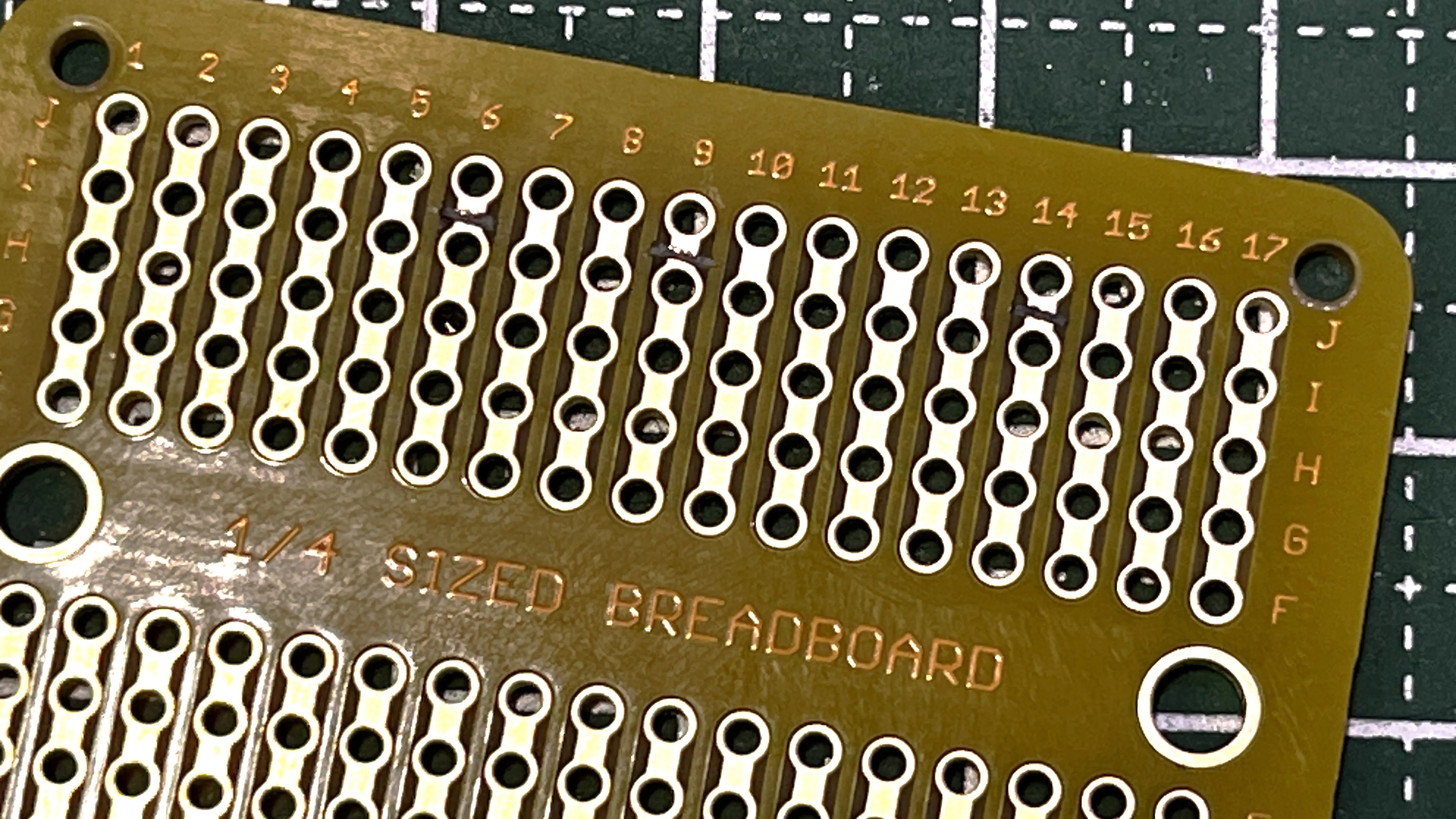
Use a carving knife or similar
Between I-J
6,9
(Change: do not connect 14)
Both sides will be grounded
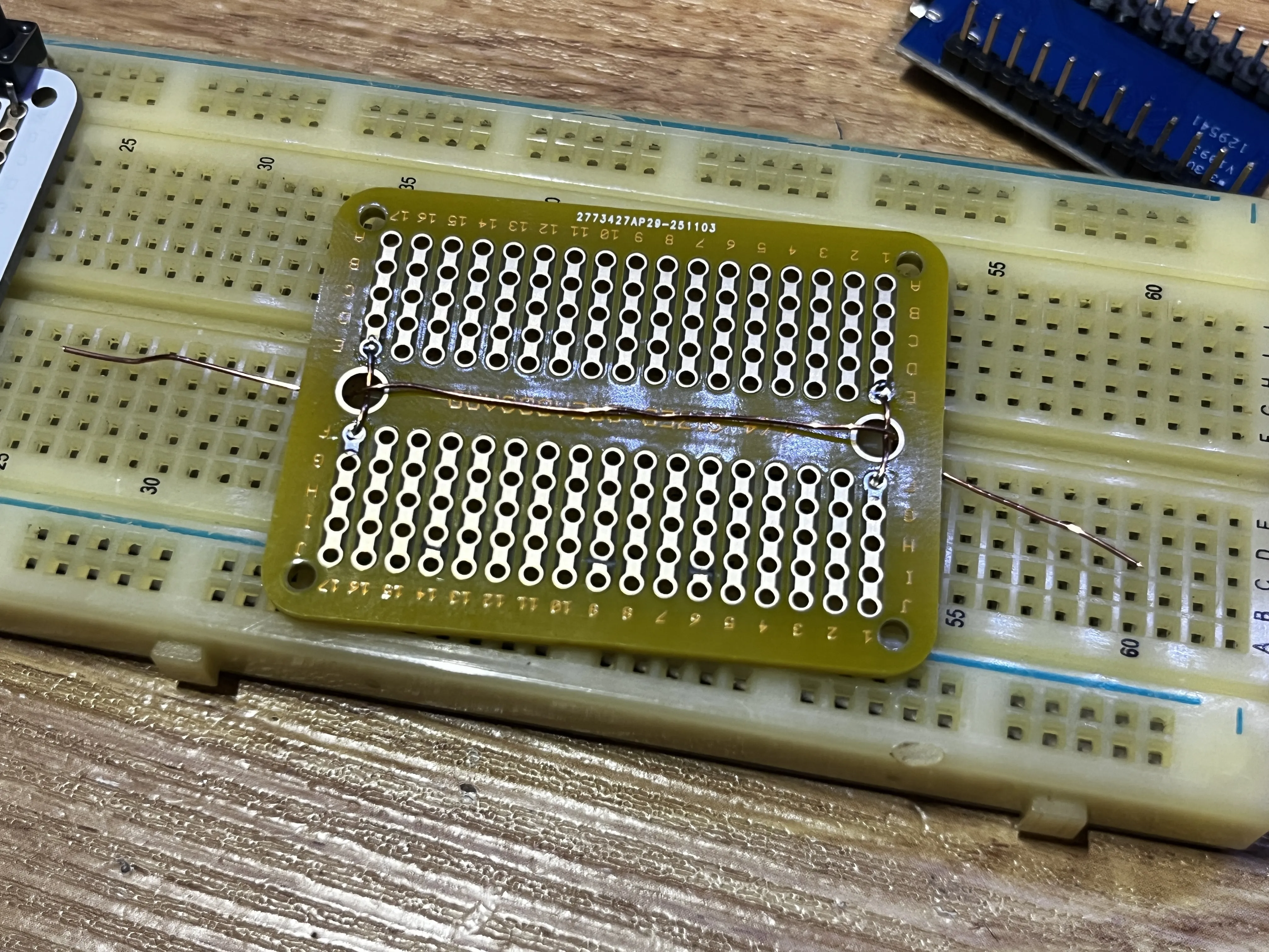
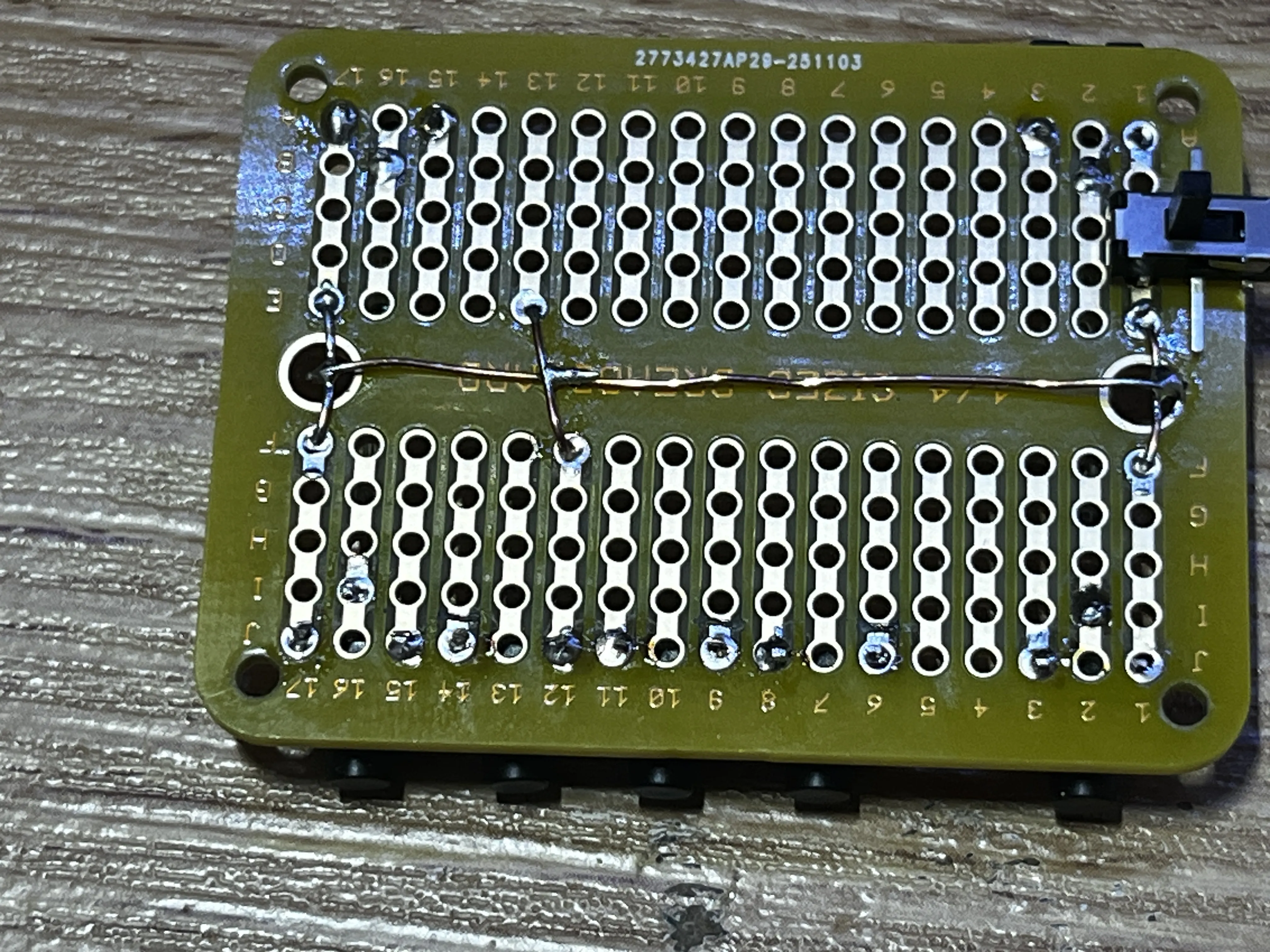
Now install the parts
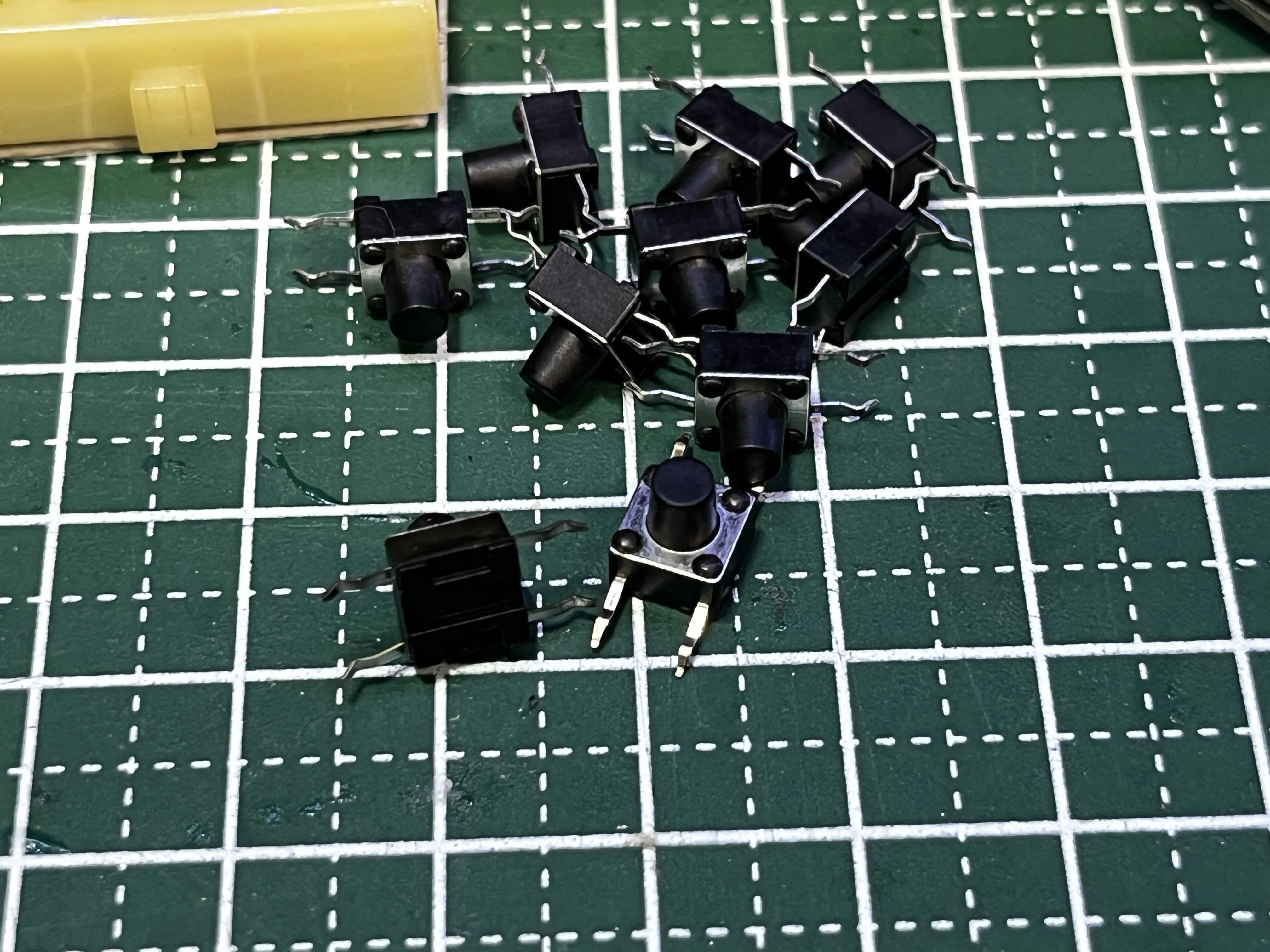
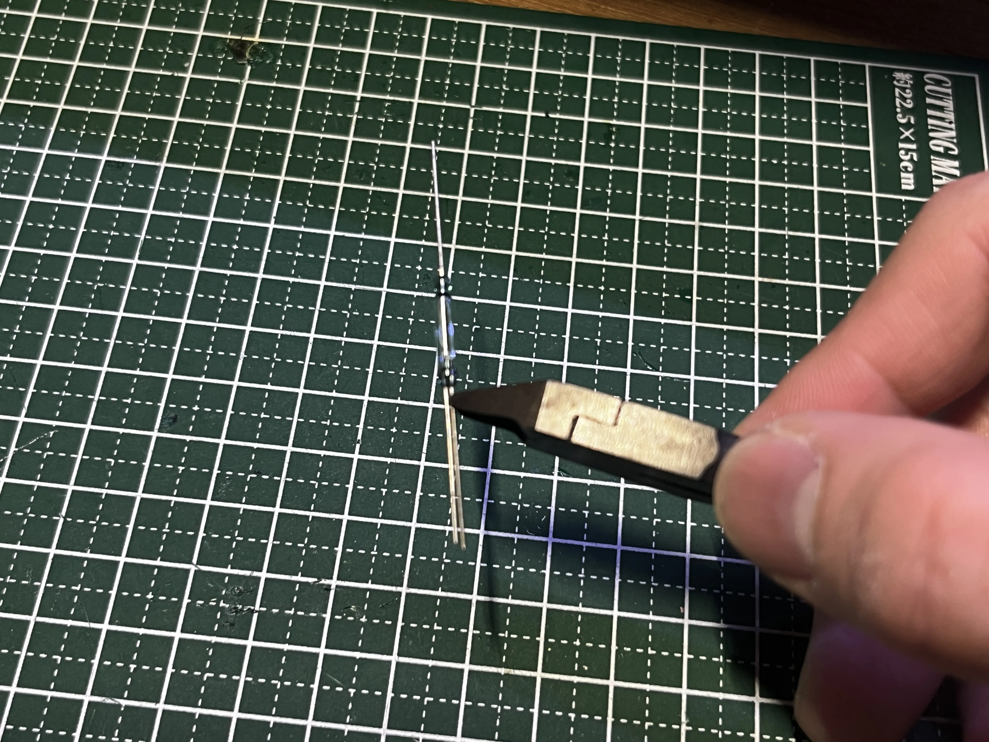
Although a normal OFF→ON switch might also work, this one has a shorter operating time
Cut the longer wire
Please be aware that the glass is very fragile
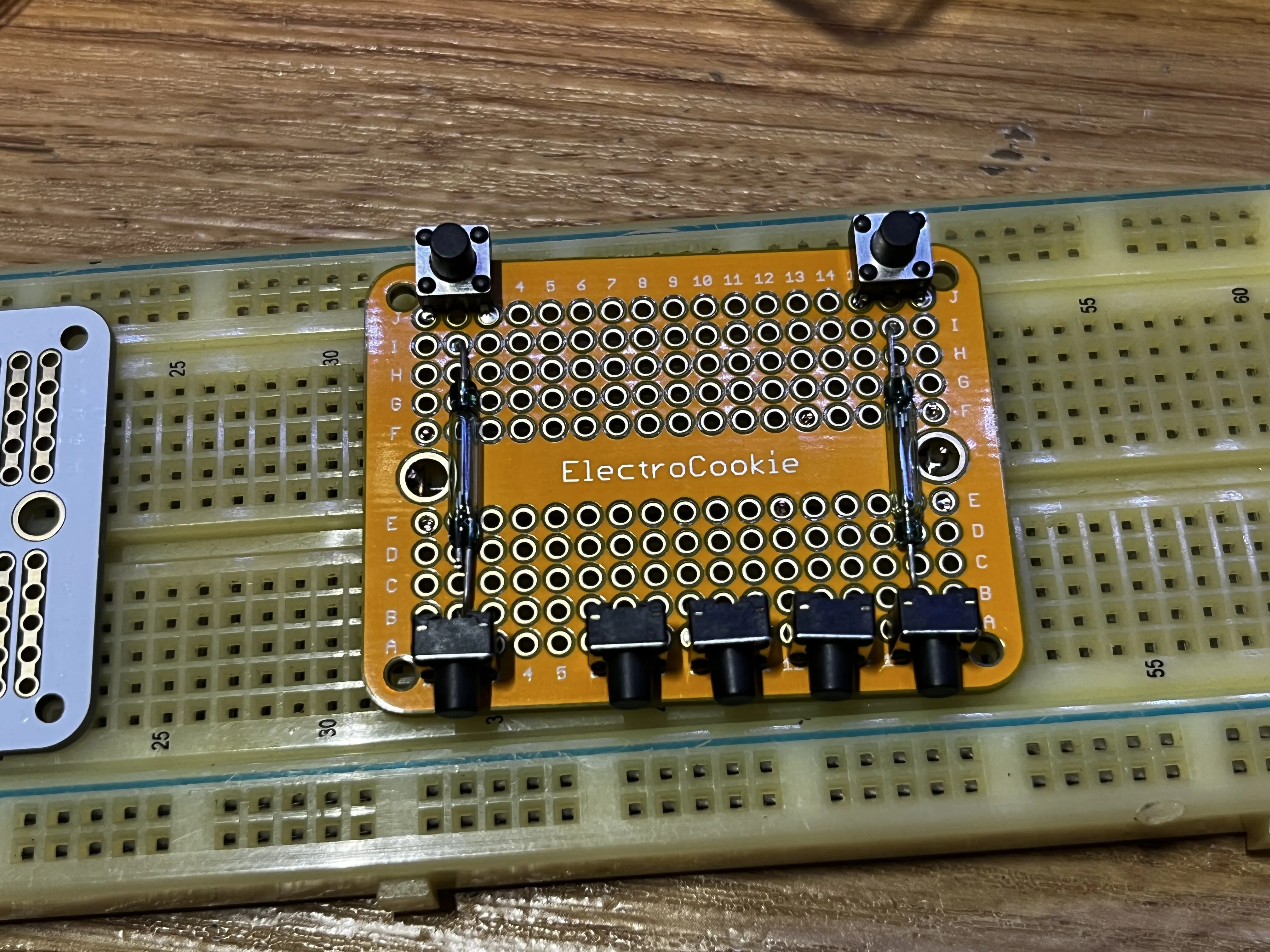
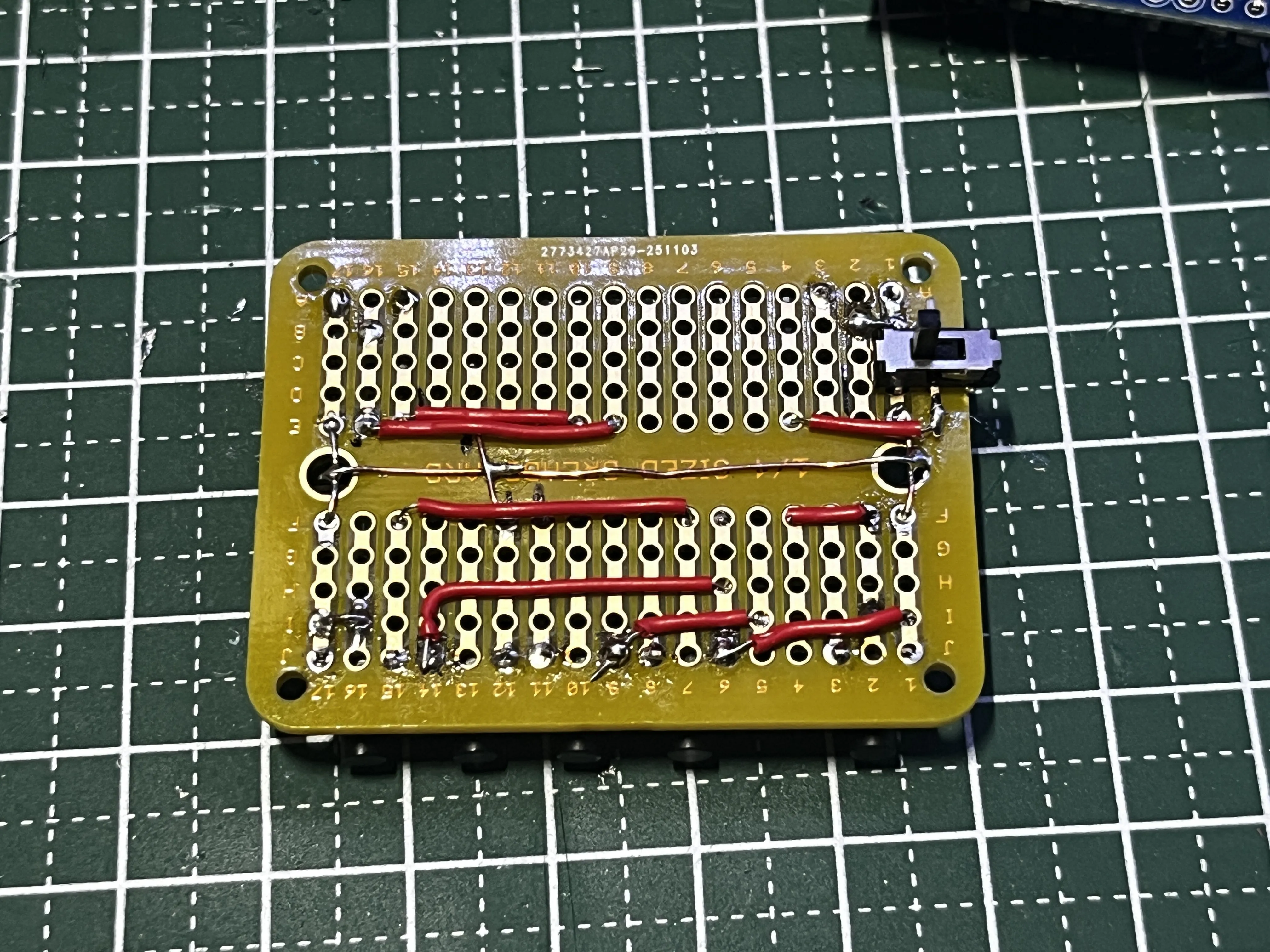
Wiring is as follows
B1-2: Glass reed wire to GND
E9-16: Glass reed wire to A2
E10-15: Button to A3
F2-4: Glass reed wire to 8
F7-15: Button to 5
I16-17: Glass reed wire to GND
I1-J6: Button to GND
I5-J9: Button to 7
(Change: H6-J14 not connected)
A reverse switch is also installed here
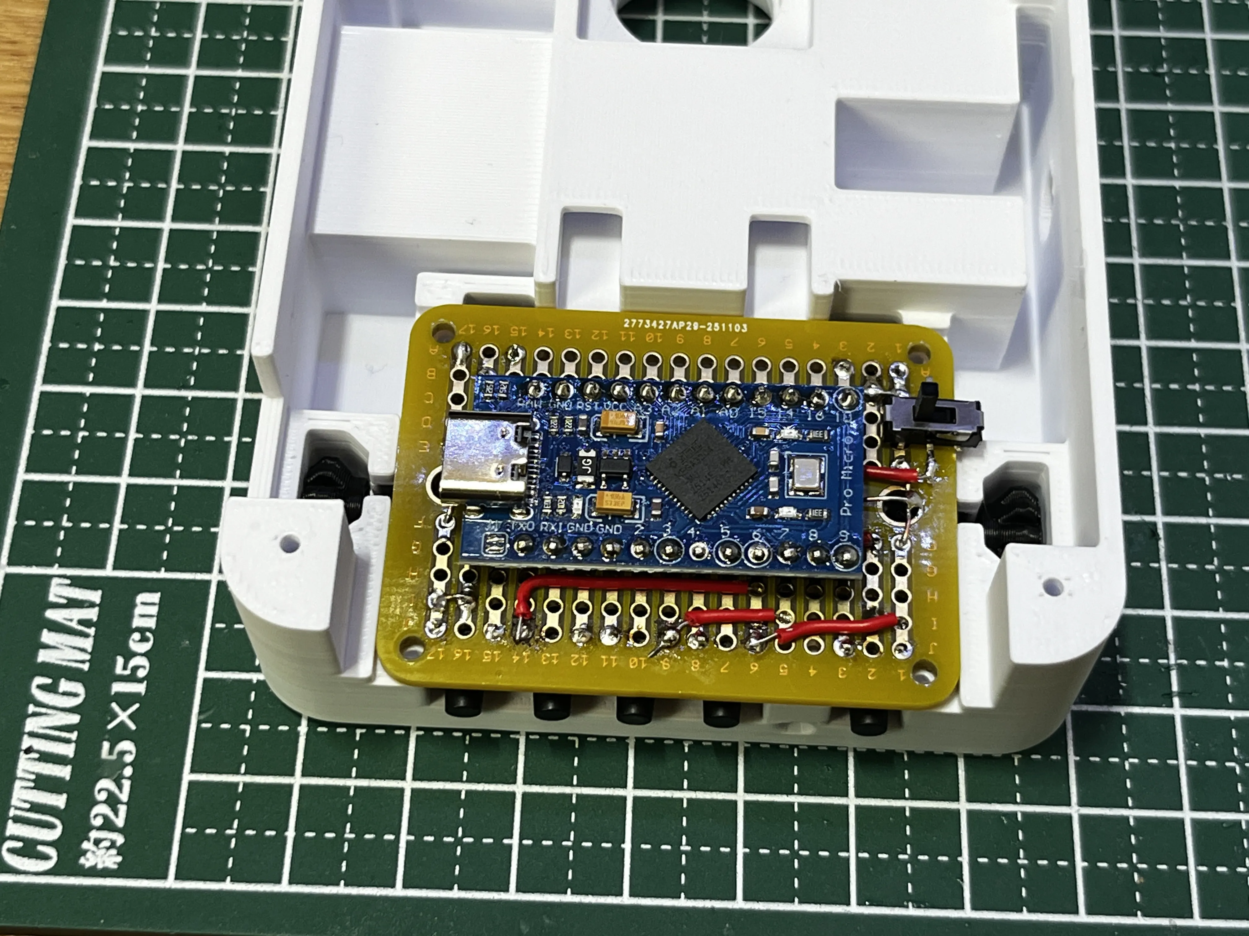
Install the switch at C-D1 and connect to E4
Install the Pro Micro
Install these three parts
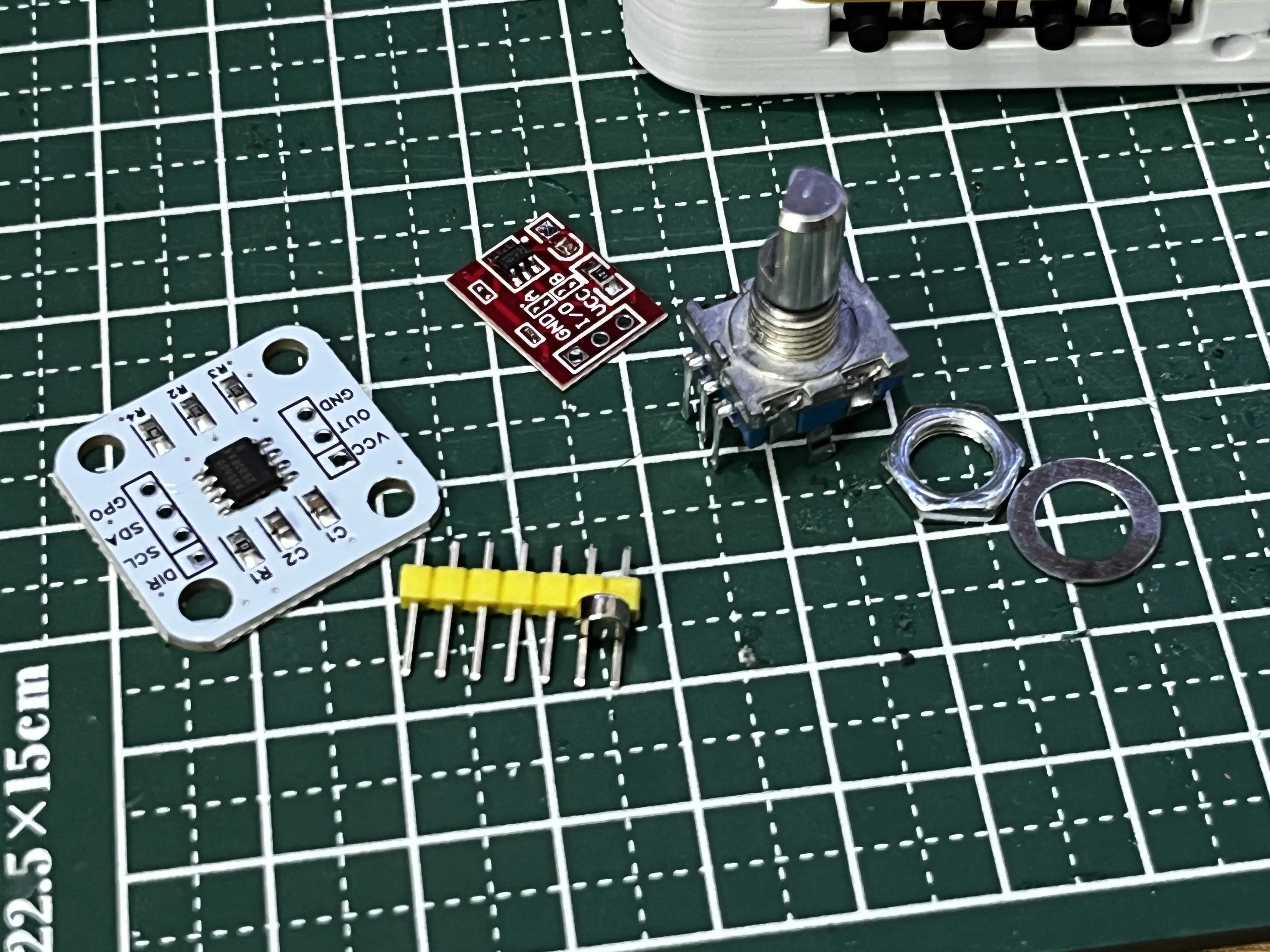
・AS5600: Part to read rotation
・Touch sensor: Detects touch (Change: not used)
・EC11: Rotary encoder with button
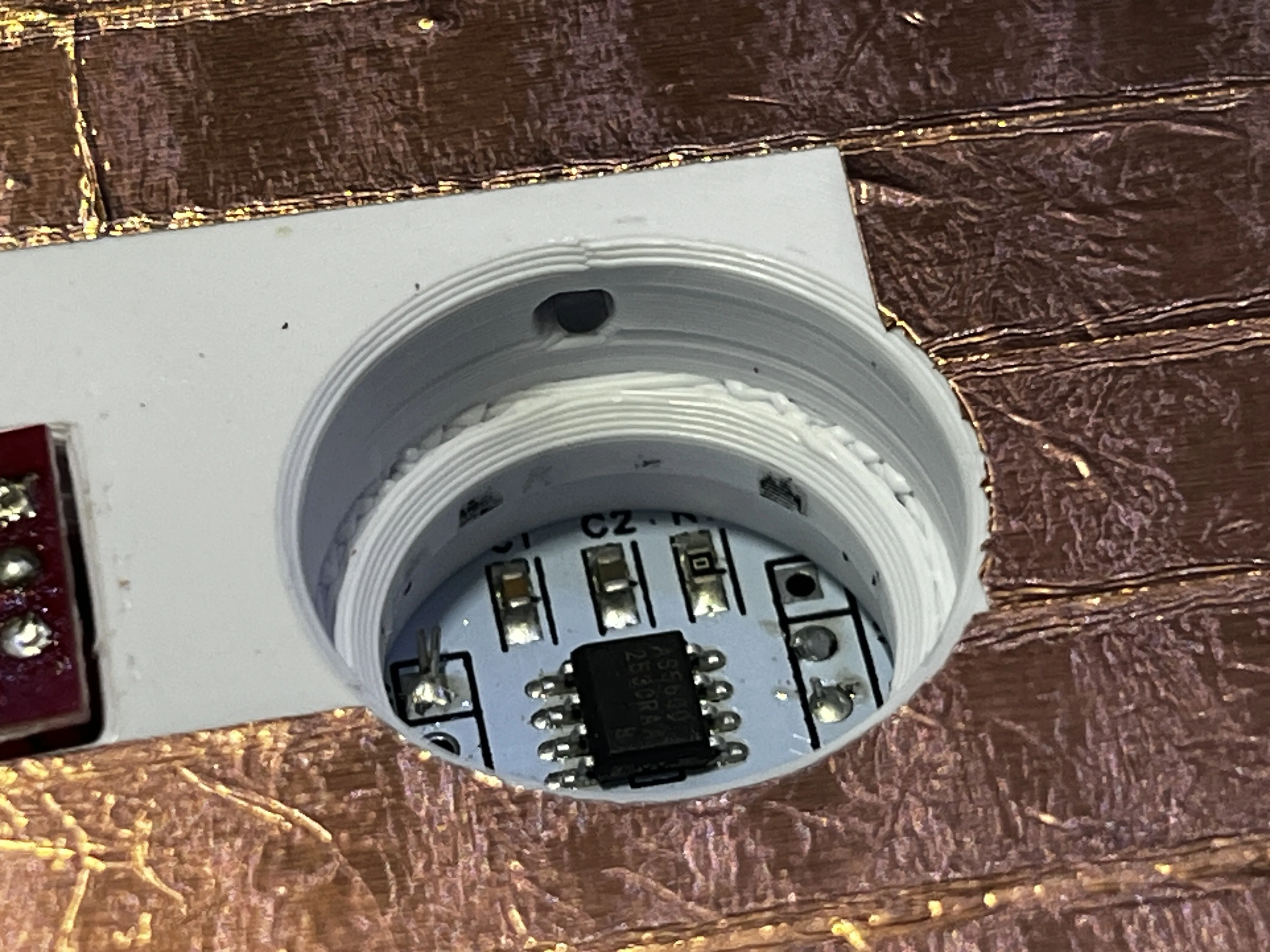
First, AS5600
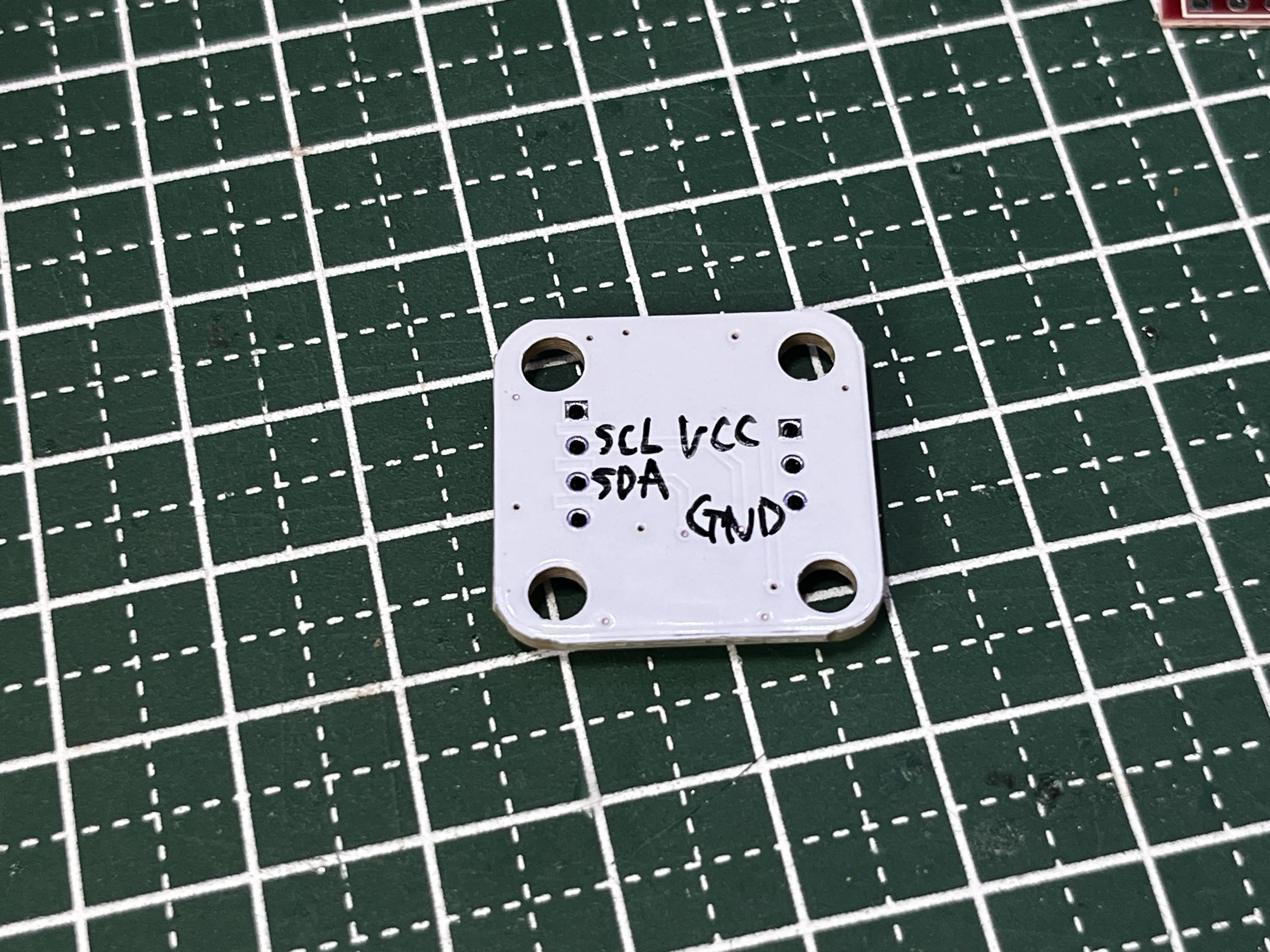
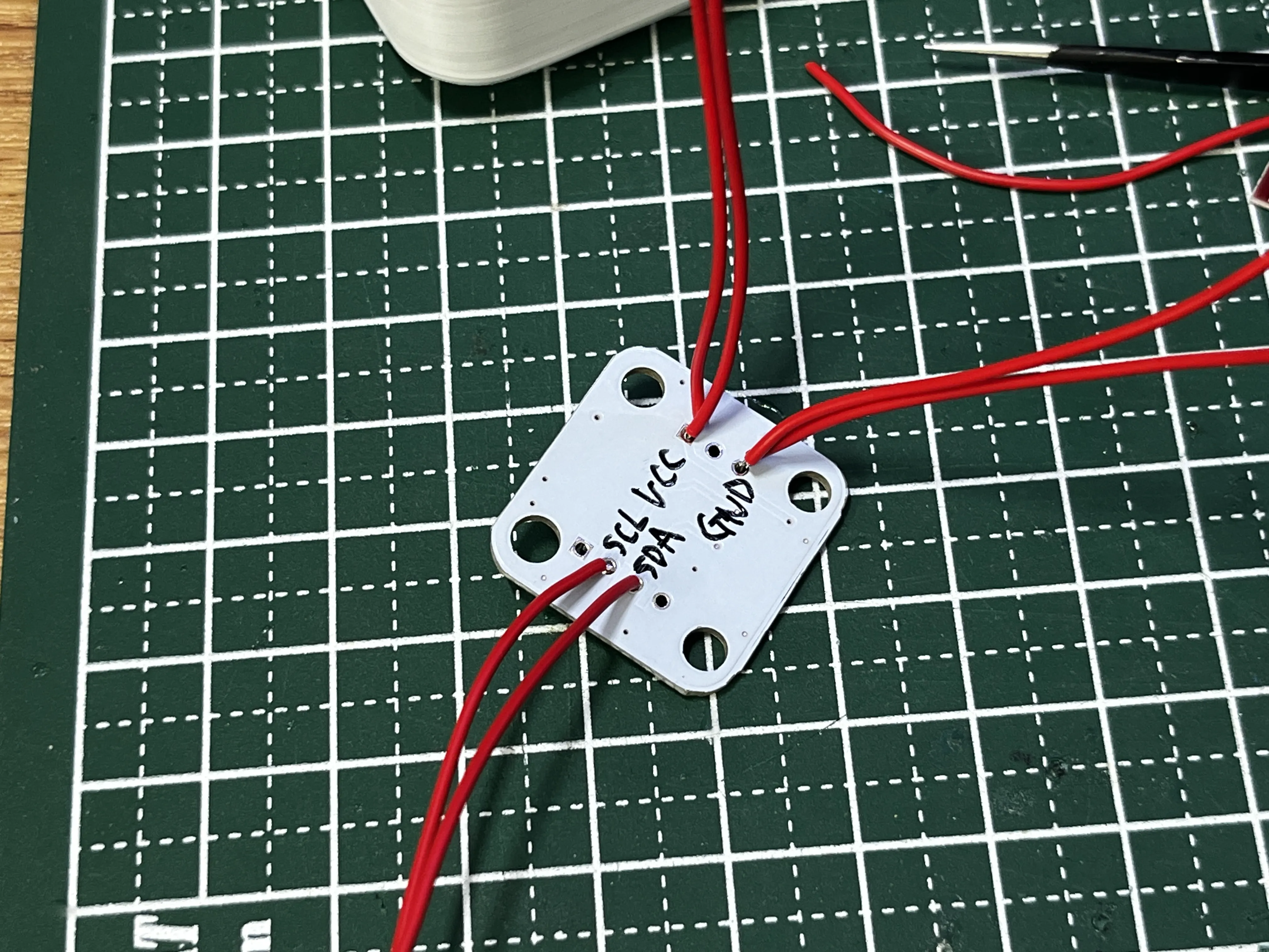
One cable is sufficient for VCC and GND
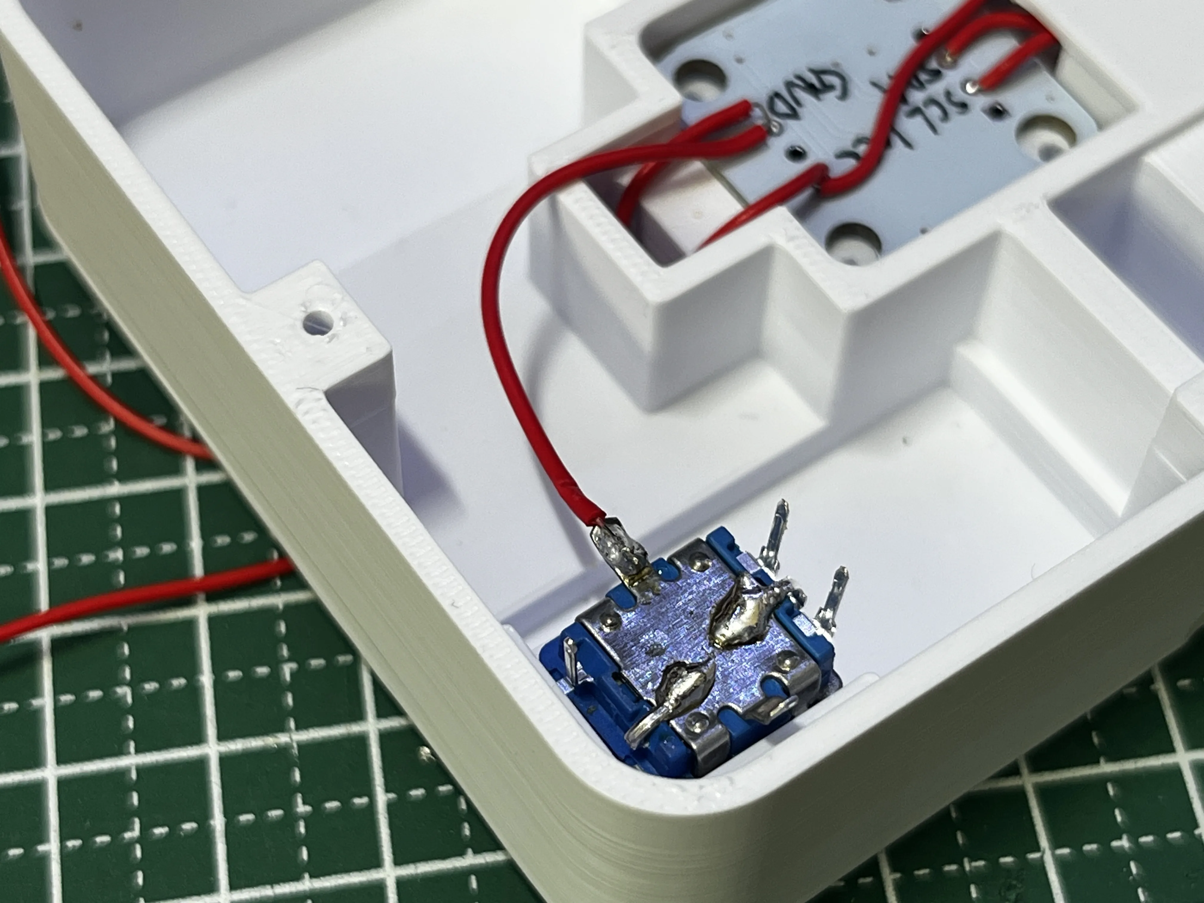
Connect AS5600's GND to EC11's GND
From EC11 to board's GND
Wire to the board
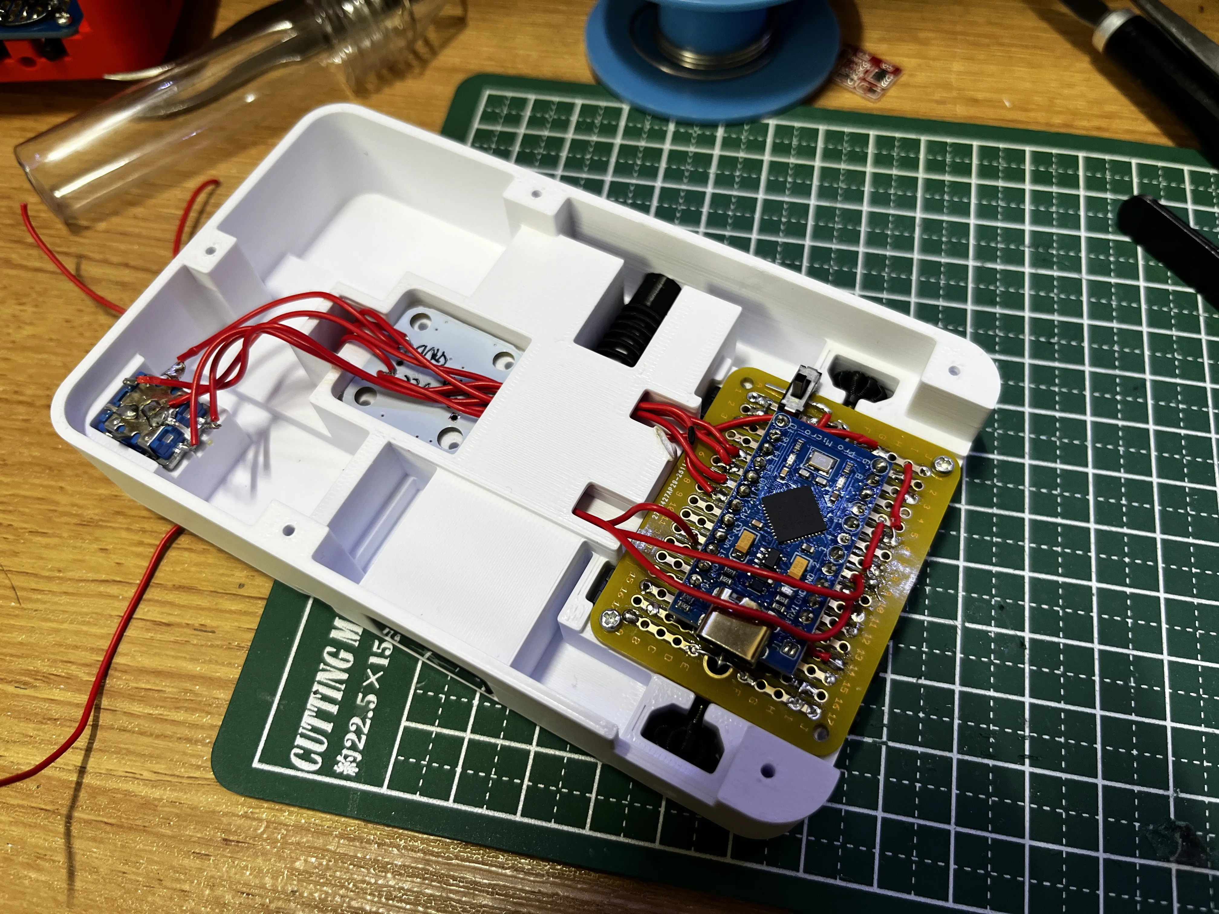
AS600
SDA 2
SCL 3
GND GND (via EC11)
VCC VCC
IC11
Phase A (left of 3 pins): 14
Phase B (right of 3 pins): 15
Button (right of 2 pins): A1
Left of 2 pins: GND
Middle of 3 pins: GND
Touch
Connect to A0 pin with a 1MΩ resistor in between
Buzzer installation
Prepare a passive buzzer and an NPN transistor
(Transistor amplifies the sound)
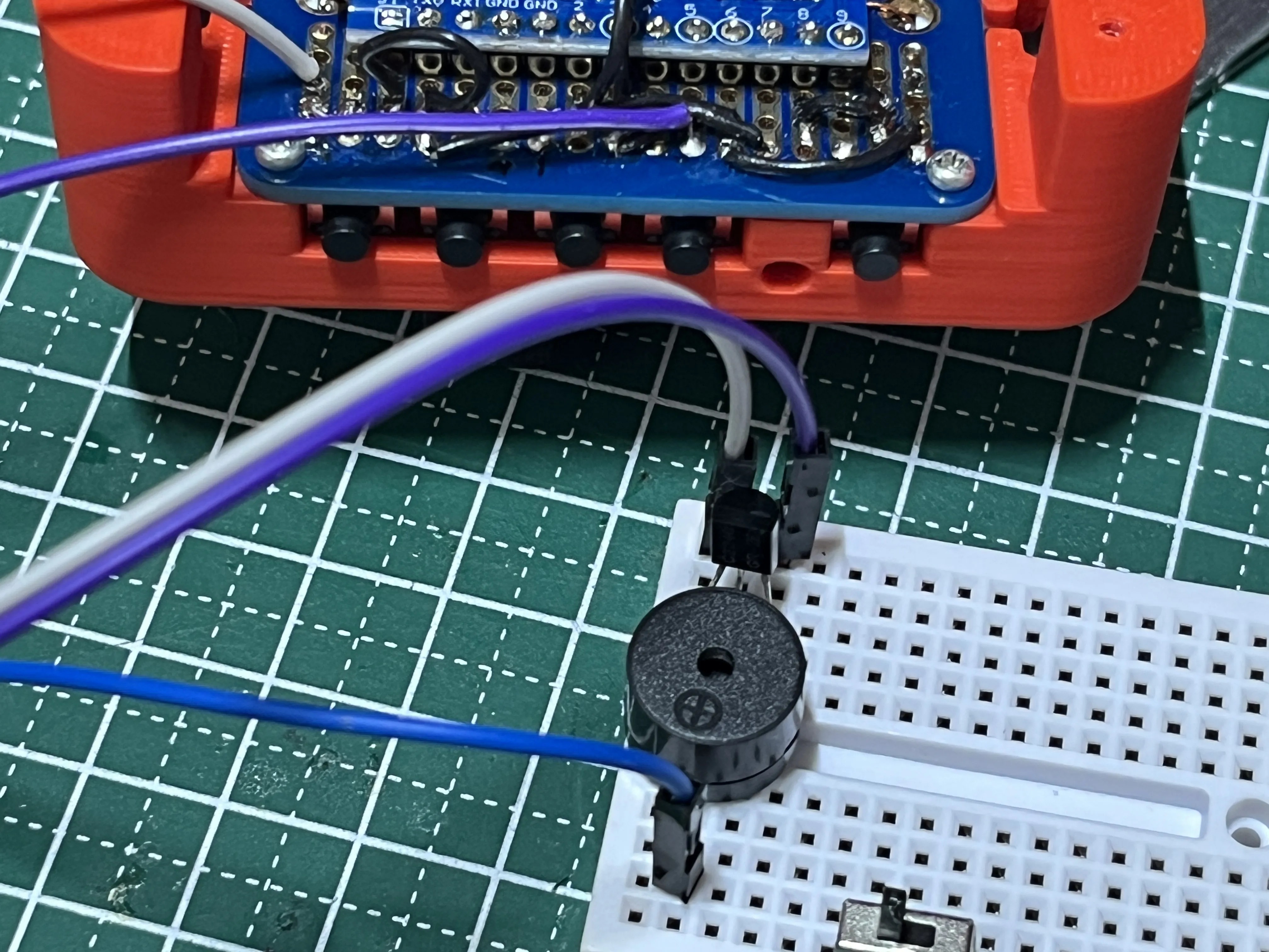
The connection is as follows
Passive buzzer plus to VCC
Passive buzzer minus to NPN transistor B (middle)
Transistor E (right) to 6
Transistor C (left) to GND
The transistor was directly connected to the buzzer
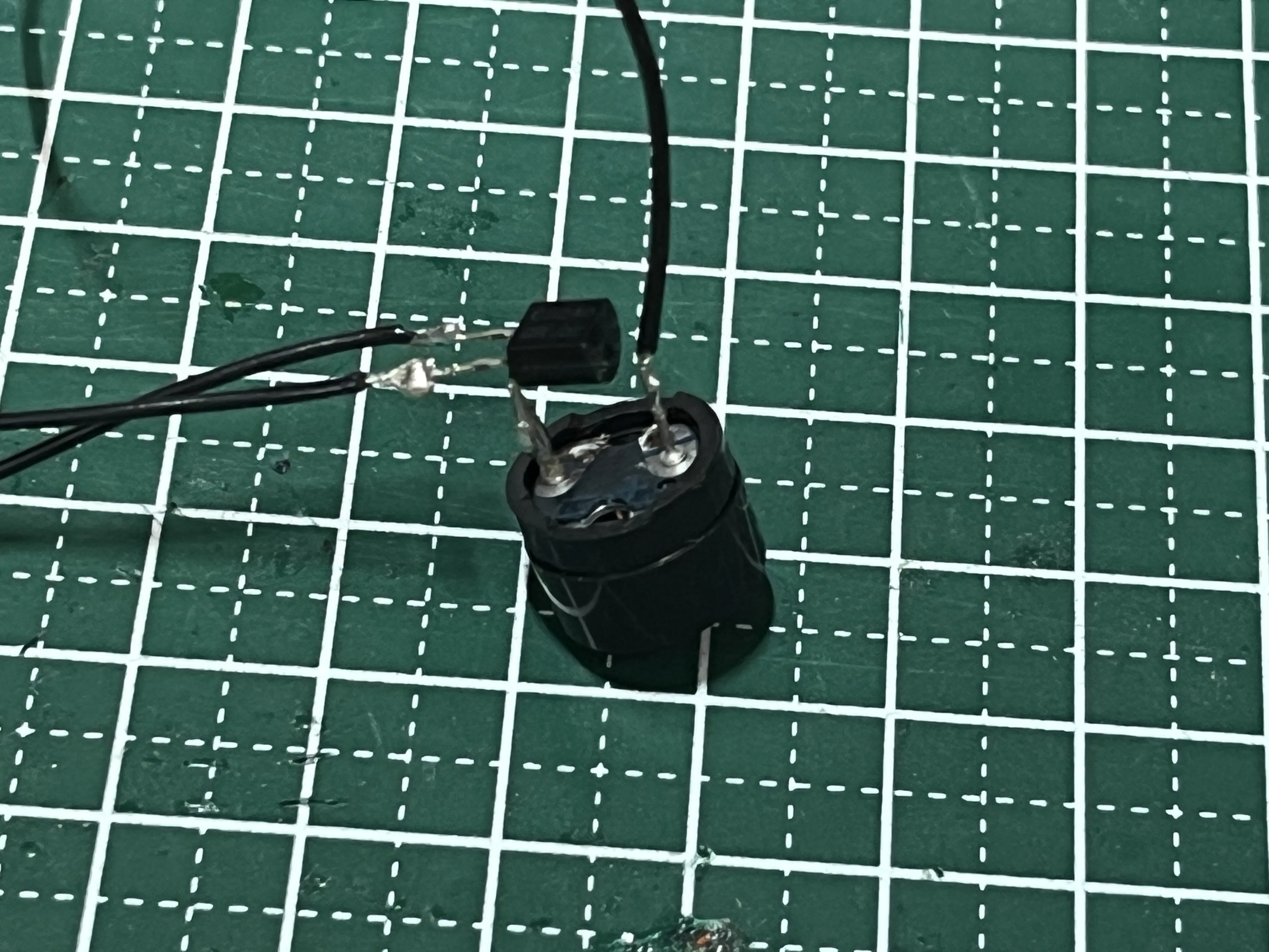
Arrange it like this
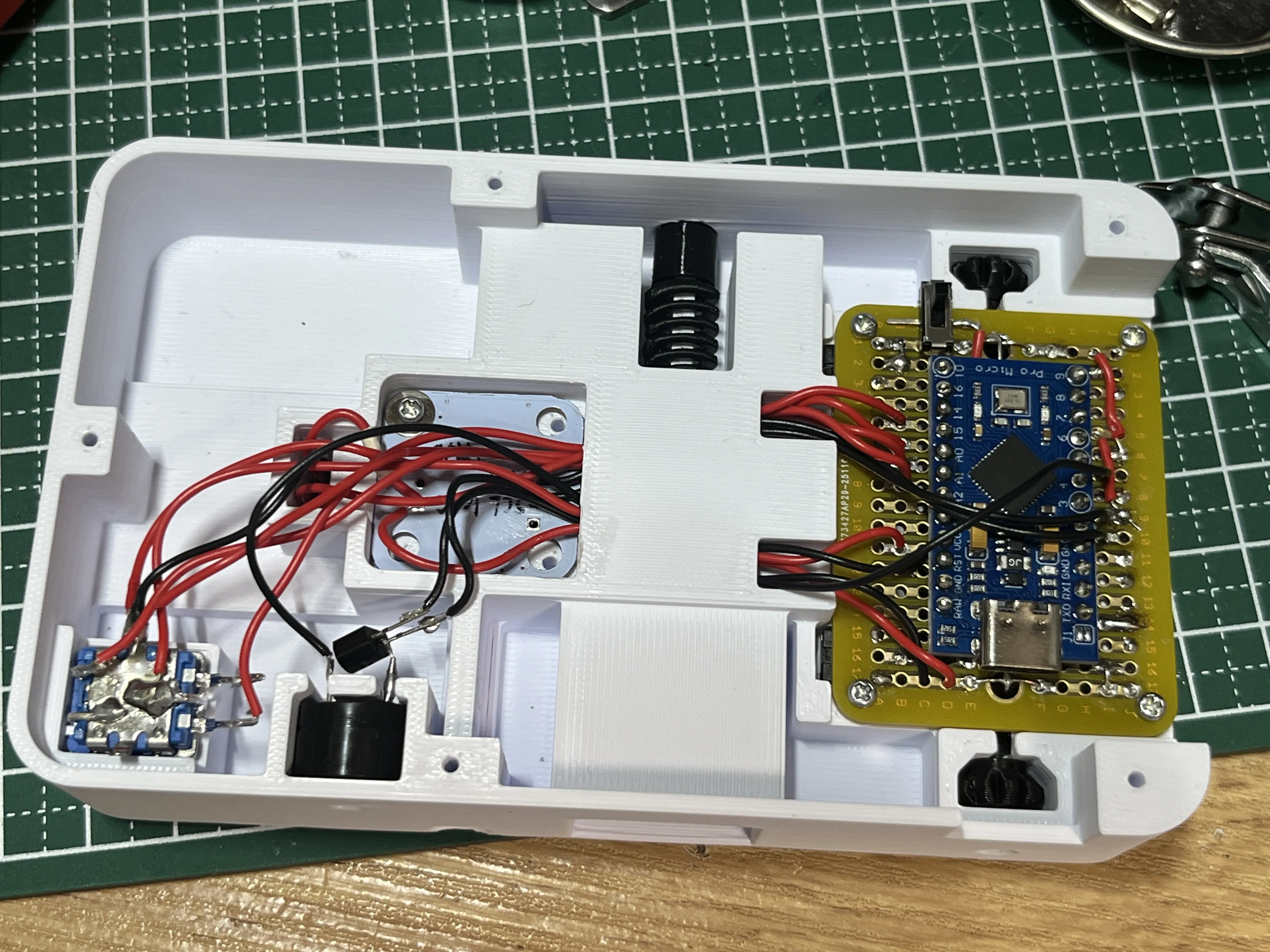
The sound is quite loud, so please adjust the volume by covering the hole with tape, etc
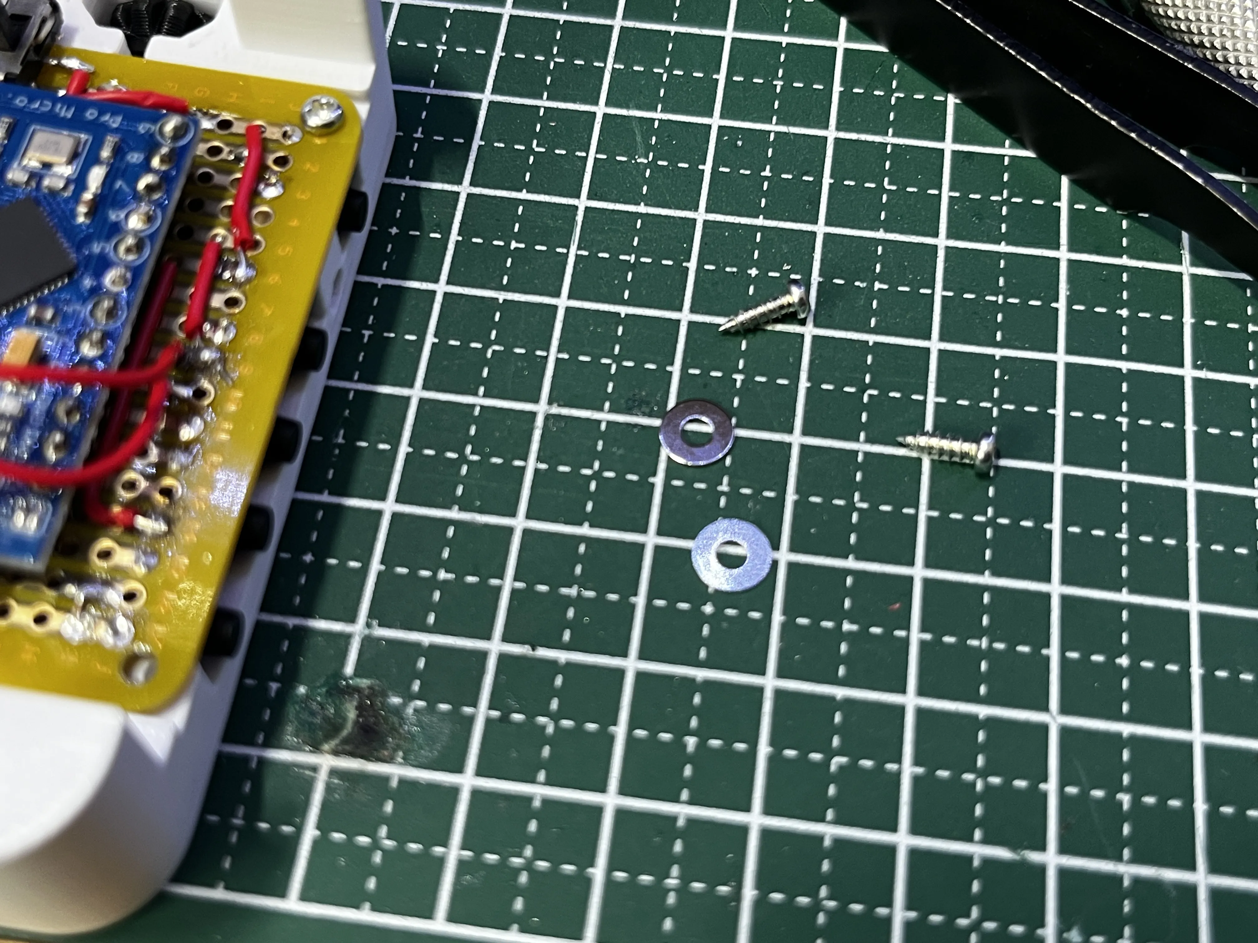
Fix the AS5600 with wood screws of about M2 x 6mm
(About 2 screws are sufficient)
Touch sensor installation
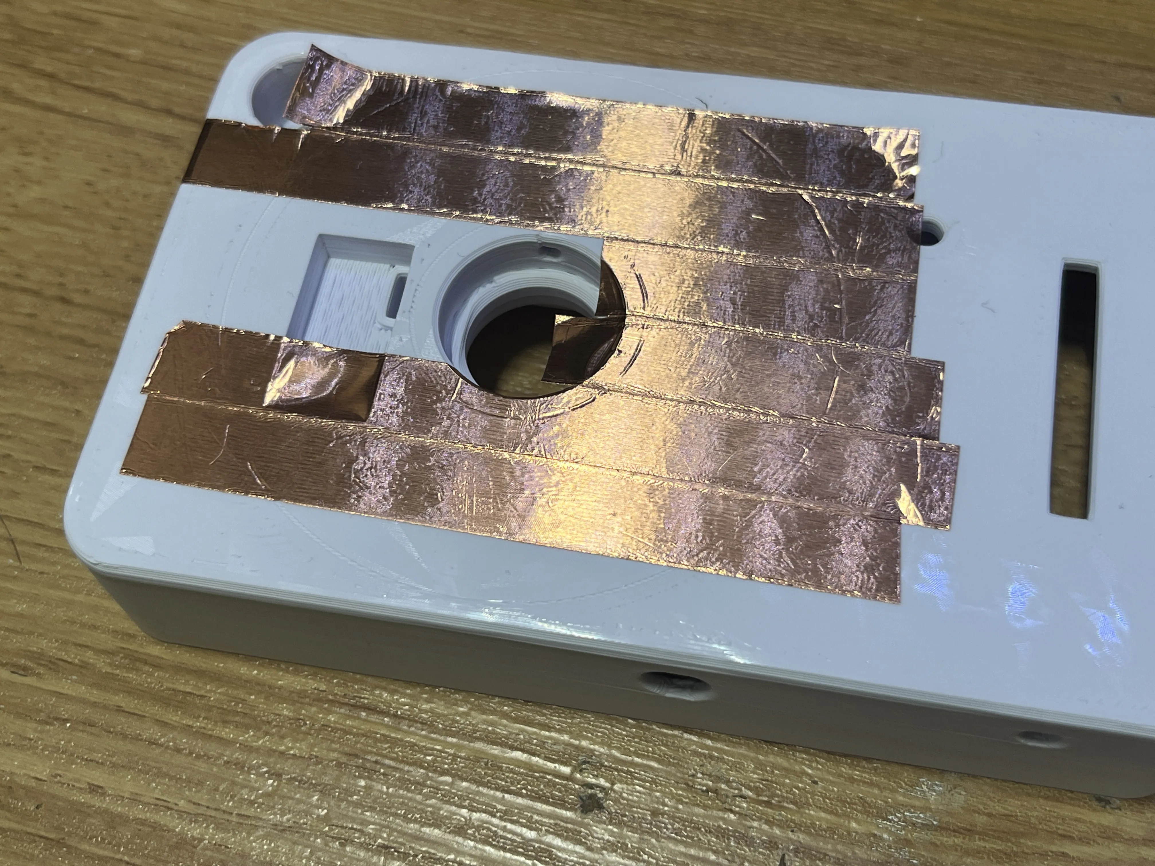
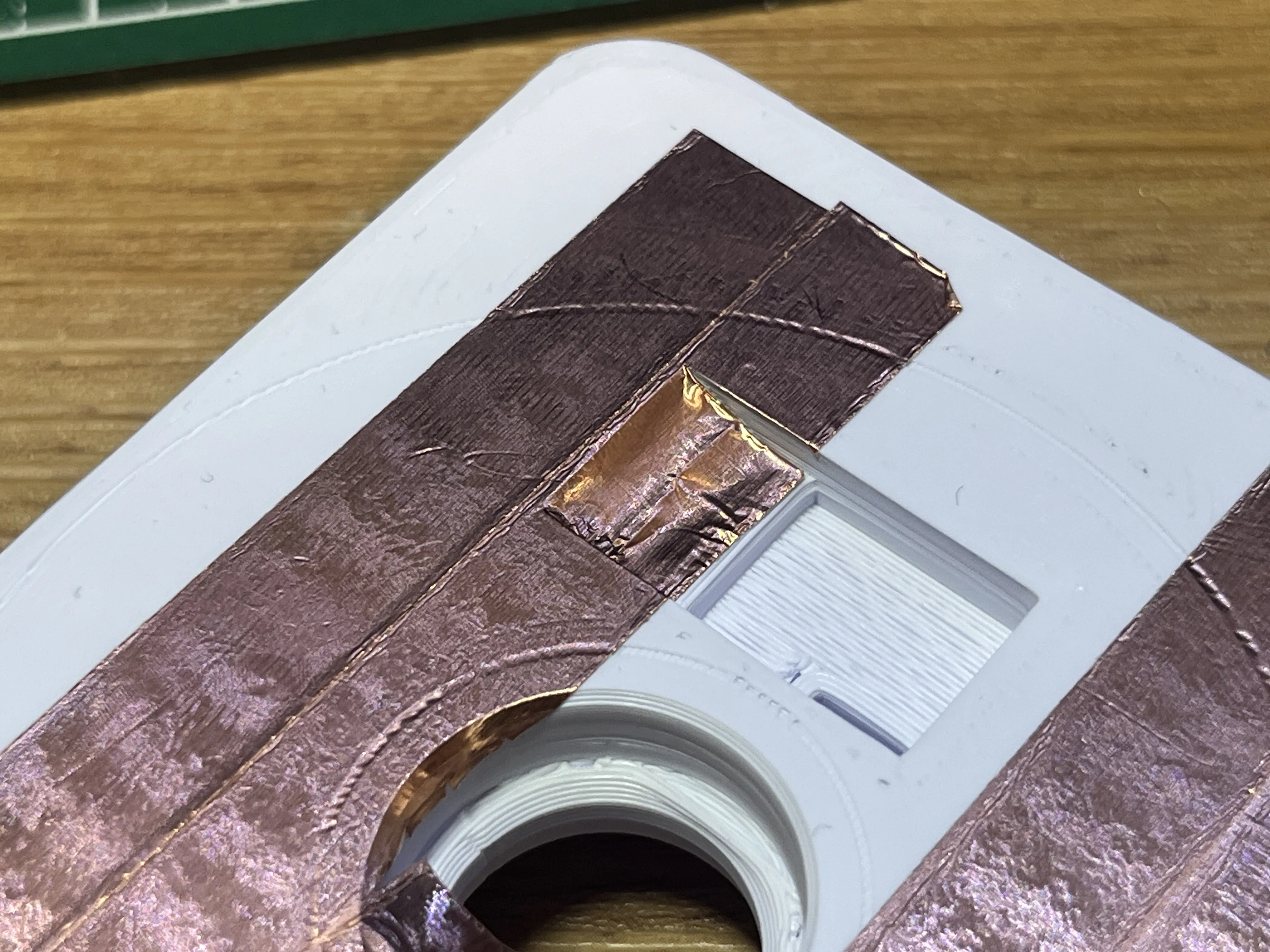
Make the part for attaching the 1MΩ resistor like this
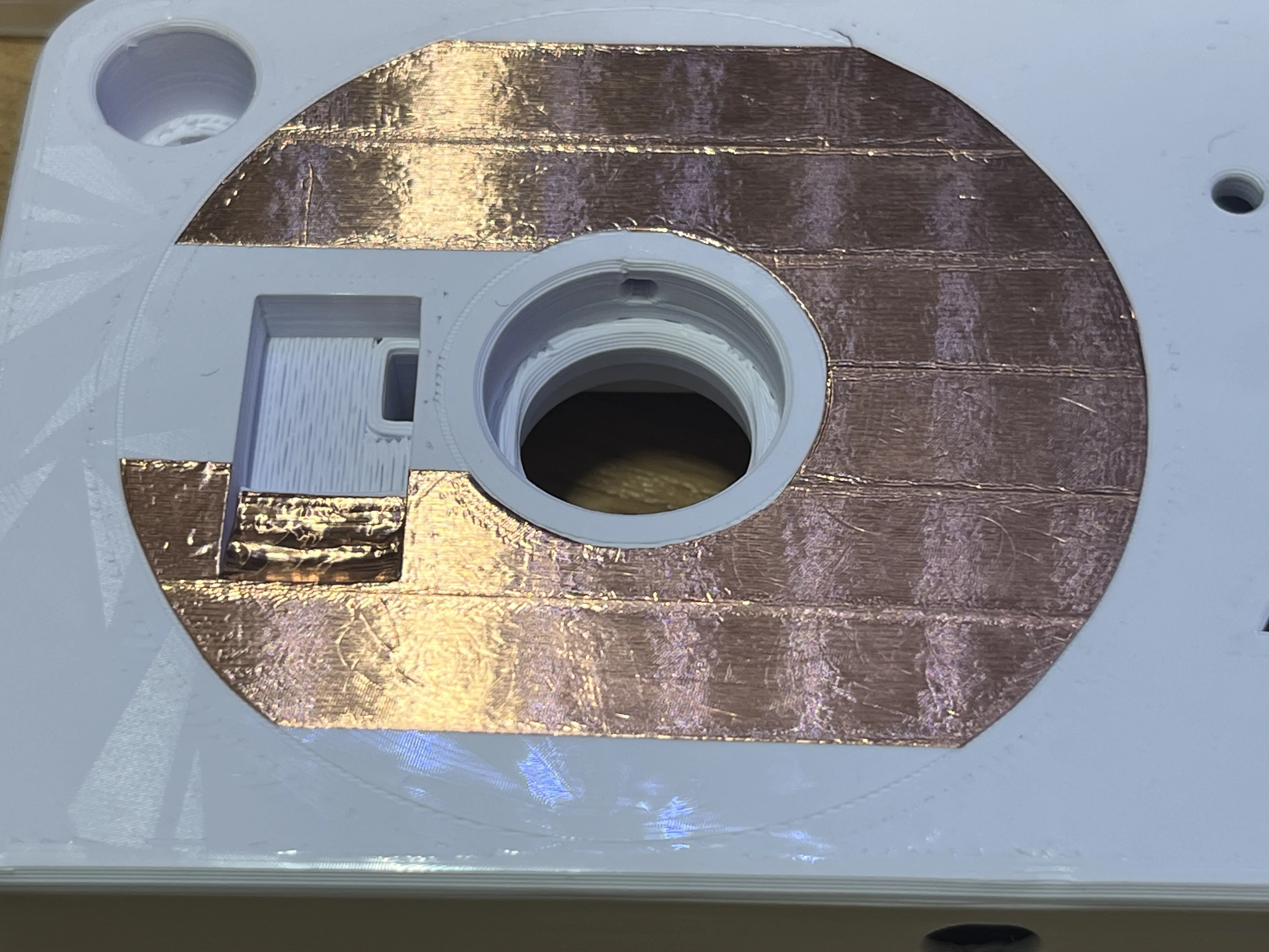
Cut the copper foil to match the outer groove
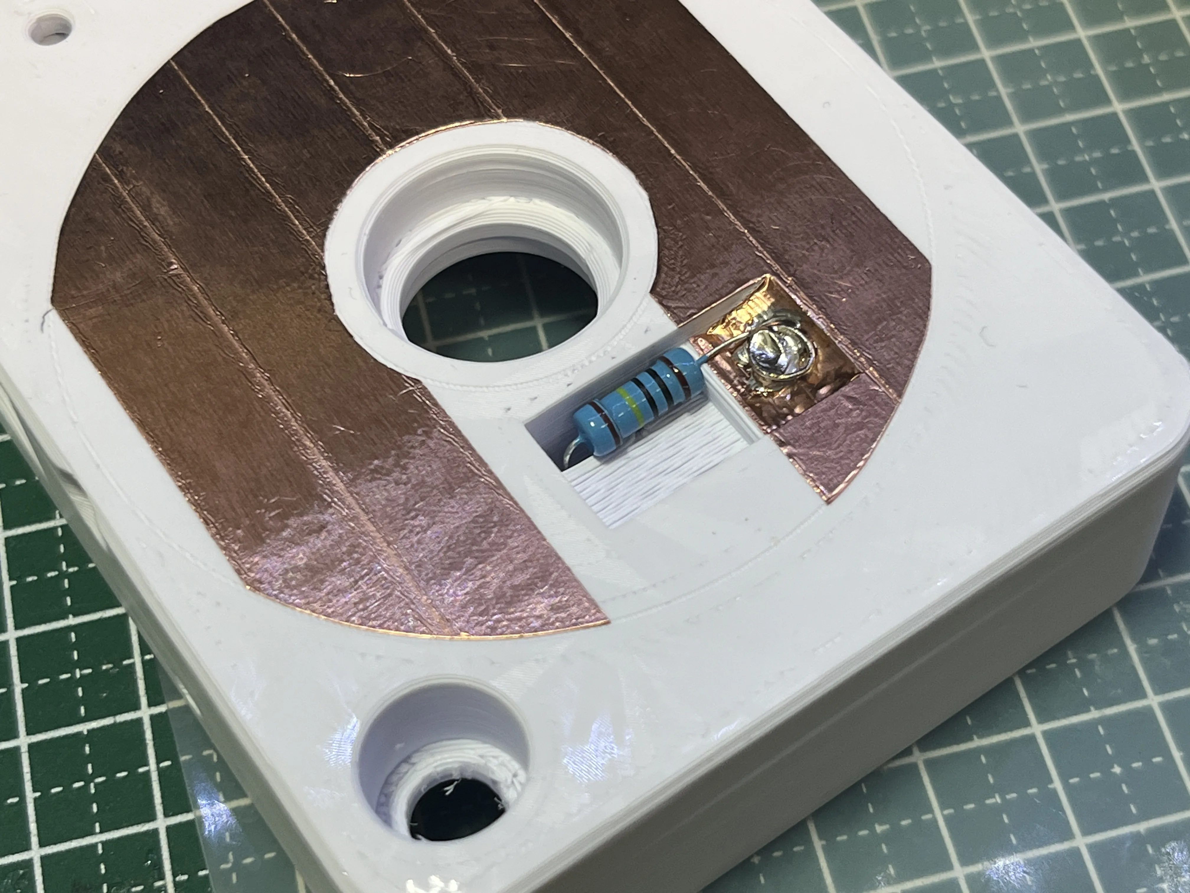
Insulate the resistor part with masking tape, etc
Wire from the 1MΩ resistor to pin A0
If the JOG is too light, it can lead to malfunctions, so install a brake
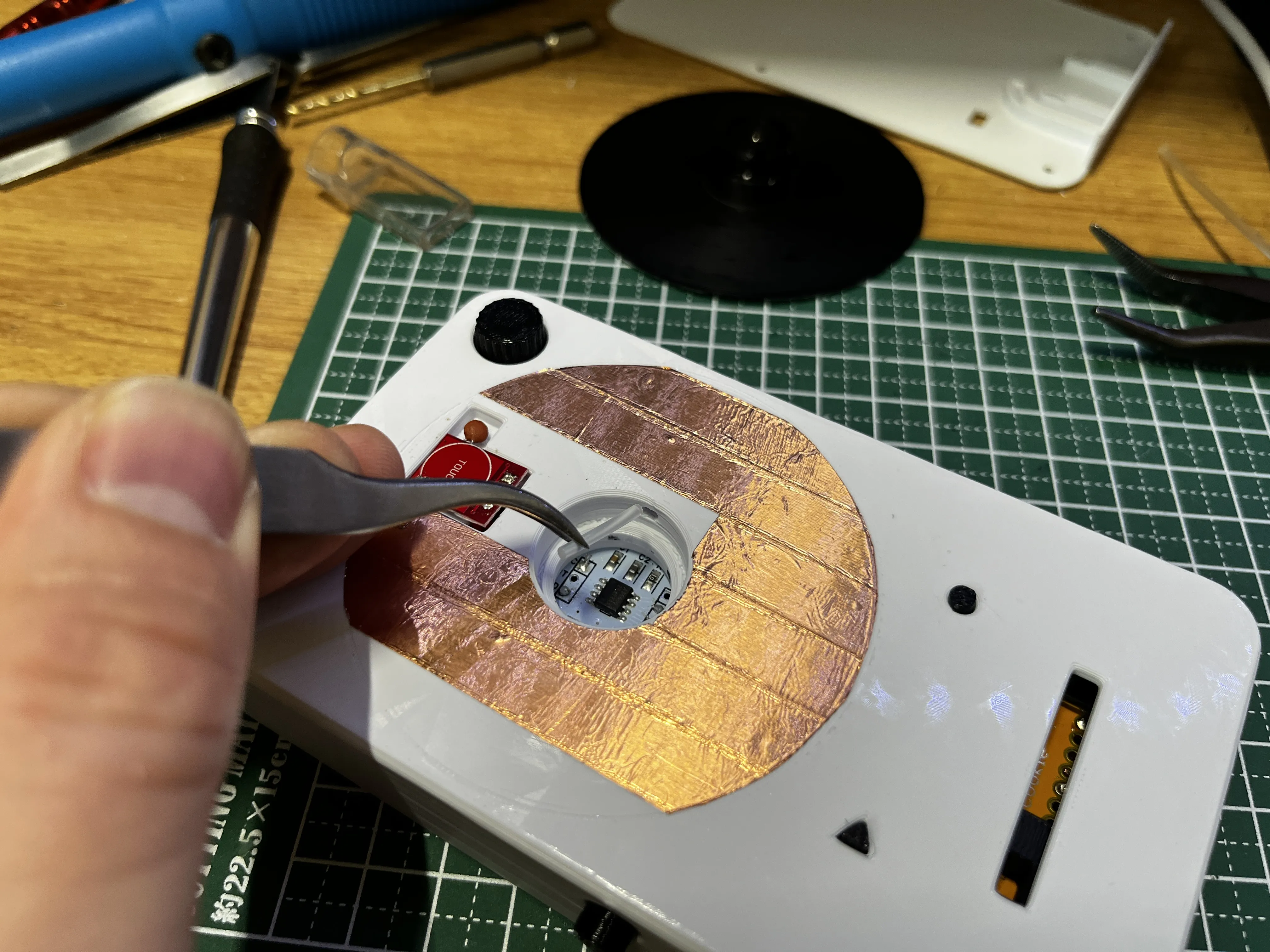
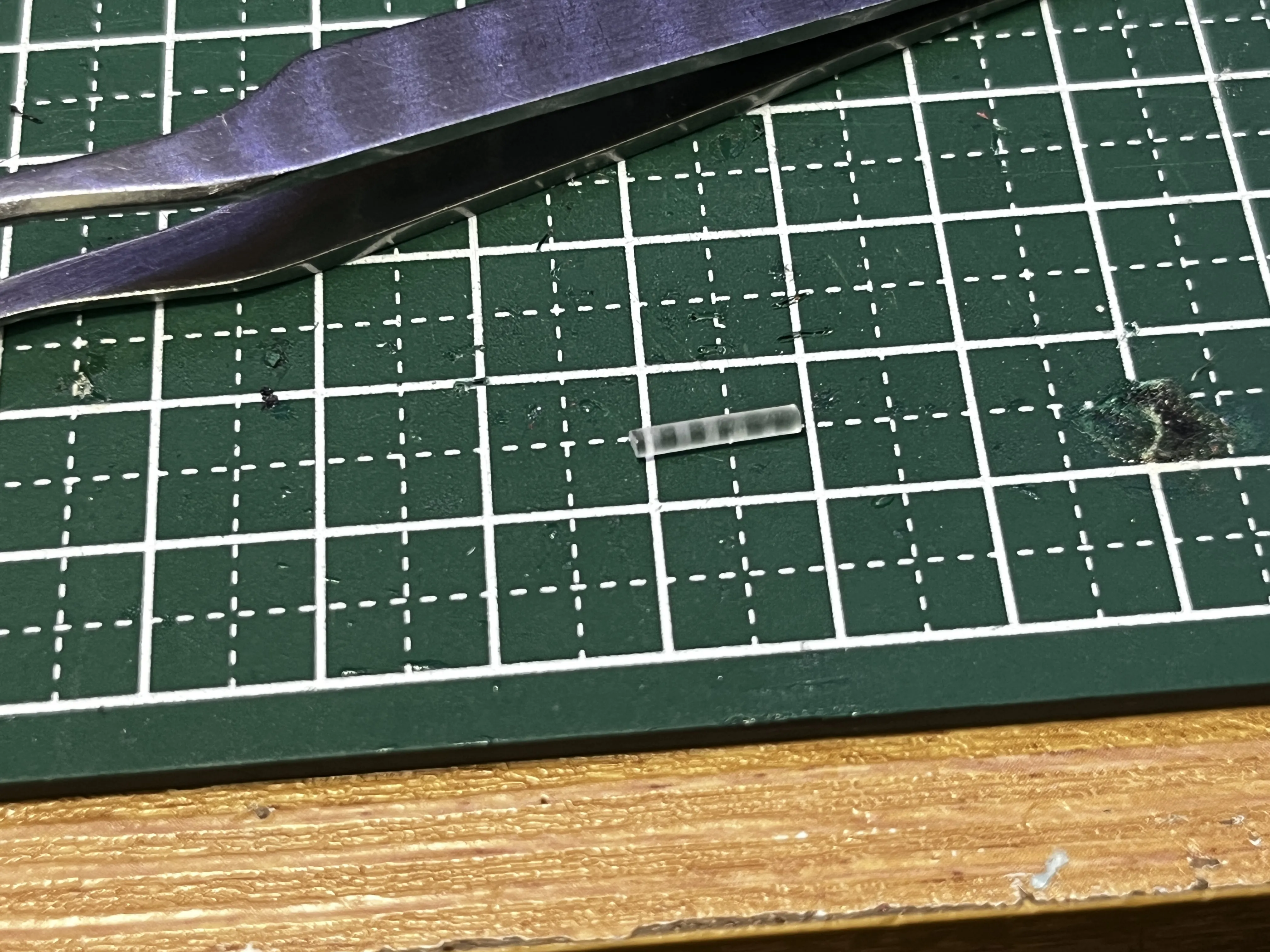
Cut about 1cm of TPU filament and insert it
Insert it here
Install an M2 x 10mm screw here to adjust the JOG's weight
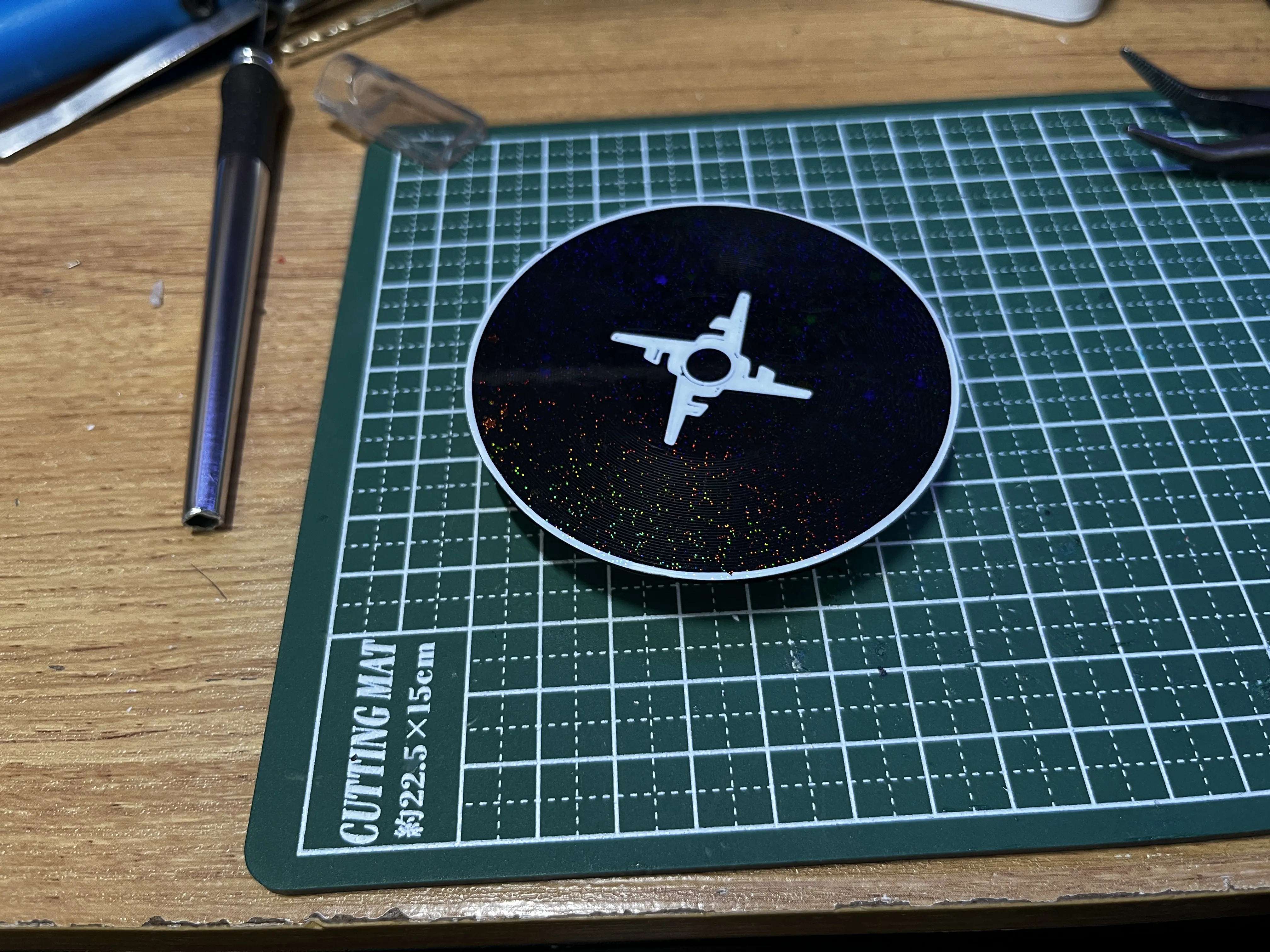
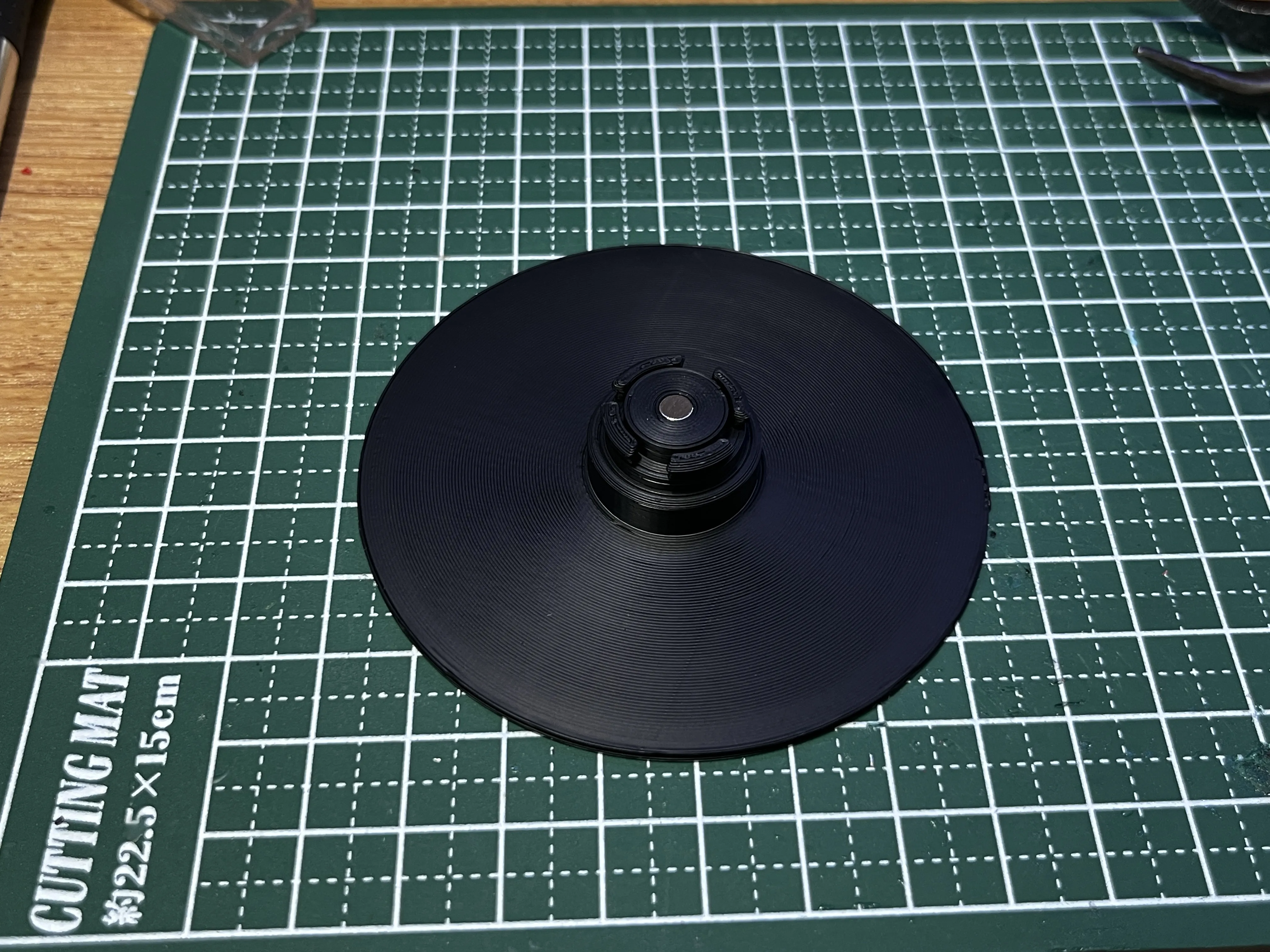
Platter installation
Attach a magnet to this part
Snap it into place
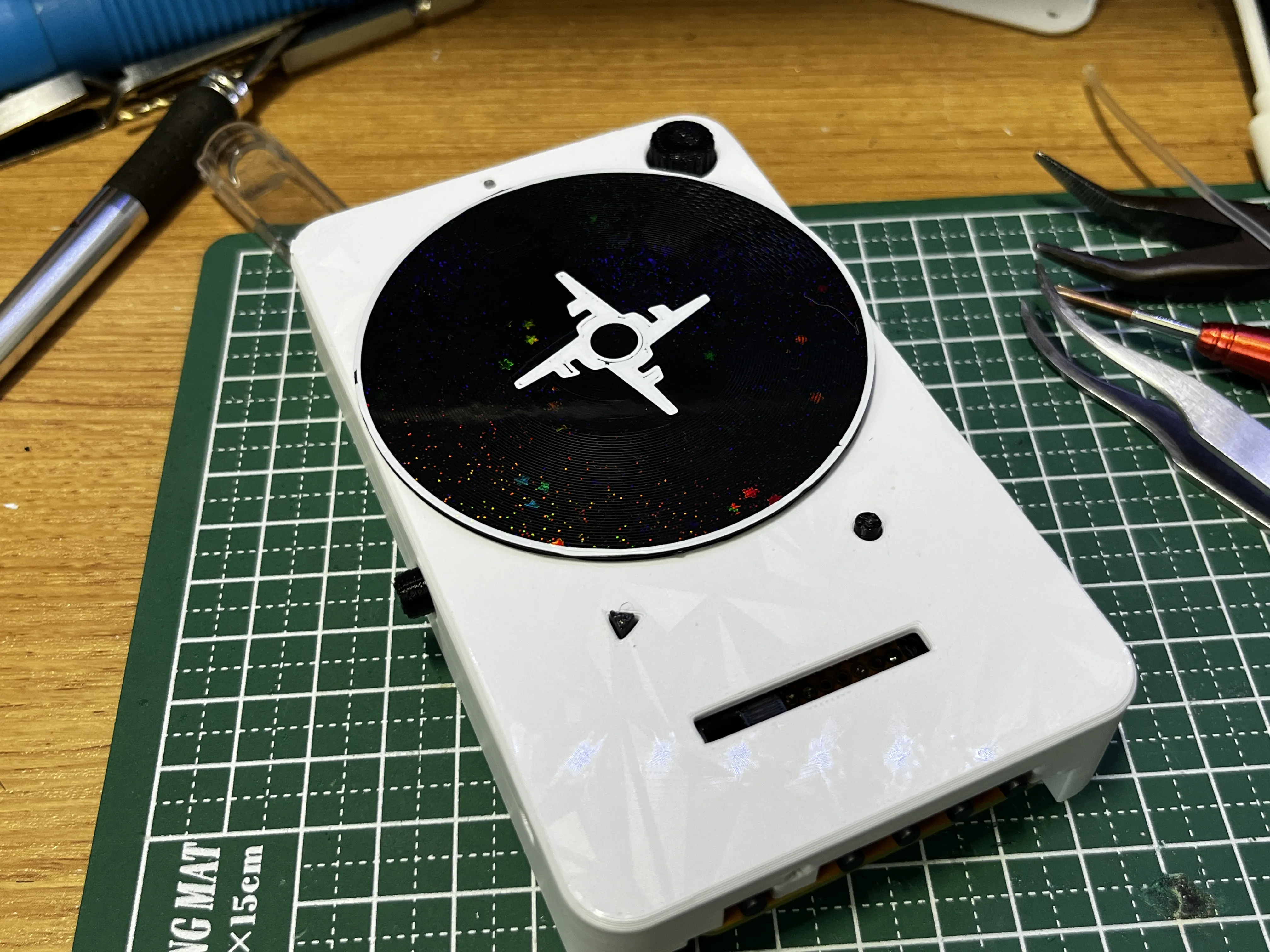
Please also attach clear TPU to this hole on the bottom
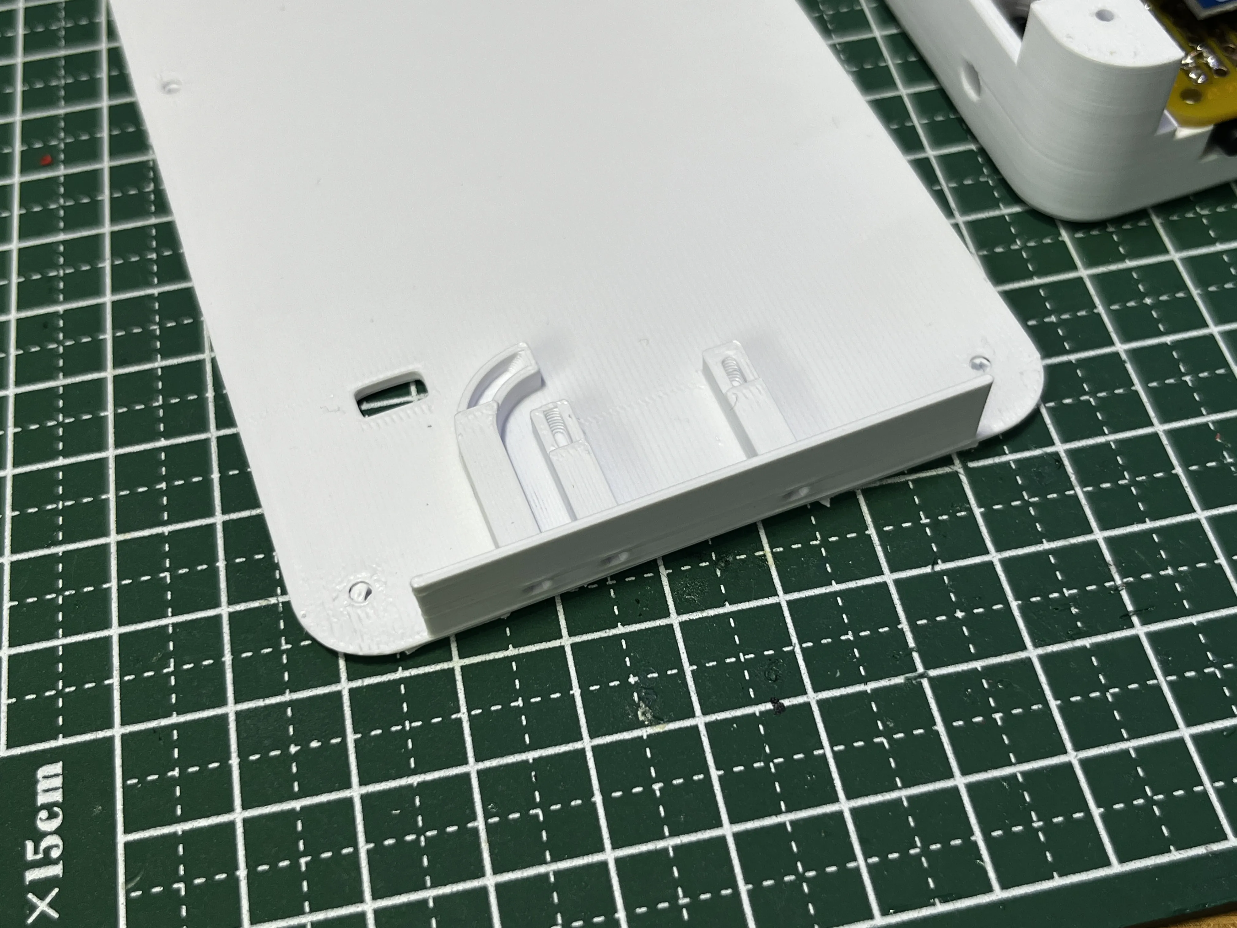
If the hole is small, please widen it slightly
Install with M2 x 6mm wood screws
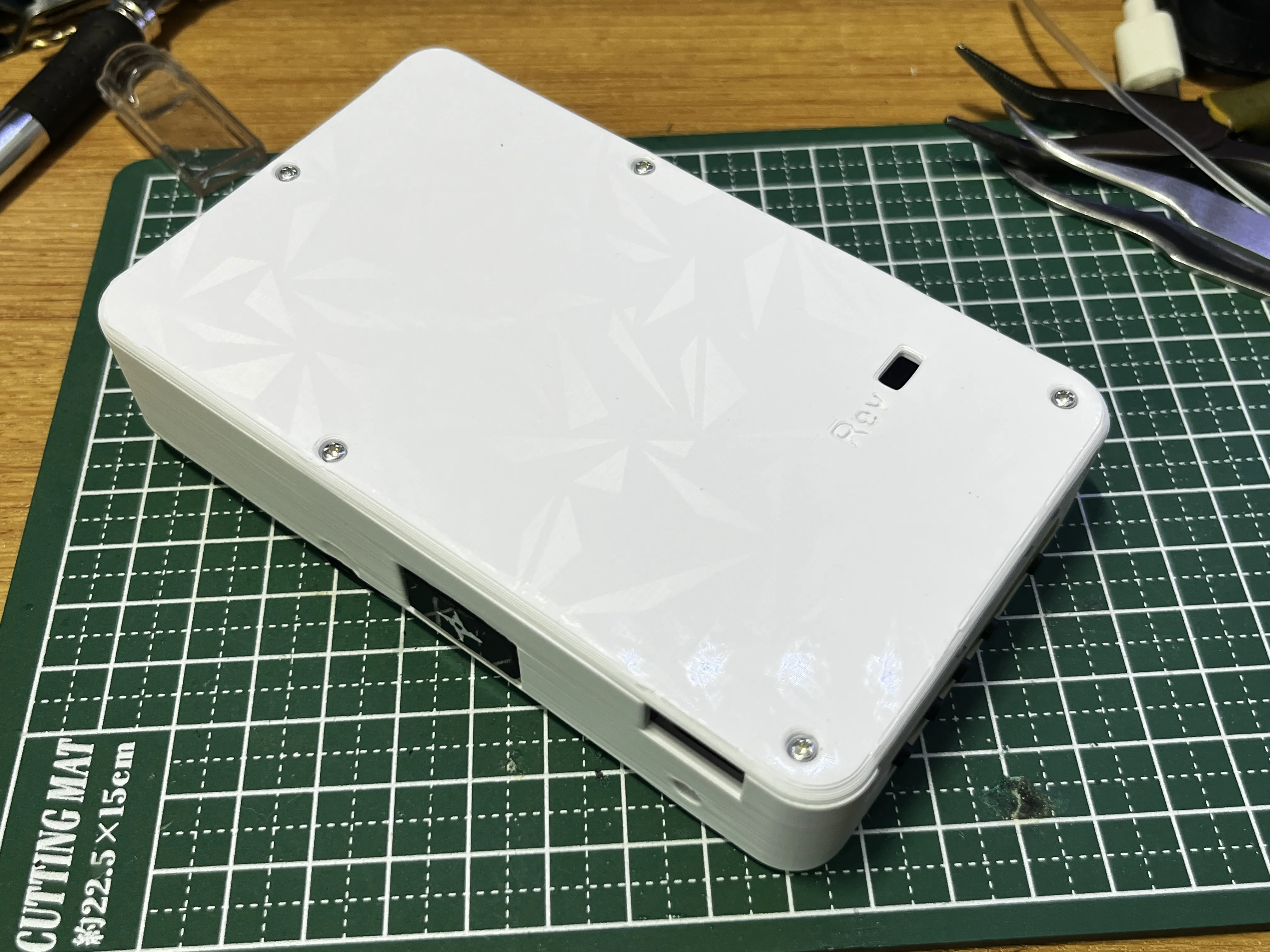
Attach non-slip material to the bottom
(Still looking for good non-slip tape for this part)
[Write program to Arduino Pro Micro]
Write data to the circuit board
https://www.arduino.cc/en/software/
Please download the Arduino IDE from here (I used Ver 2.3.8 during creation)
After launching, copy and paste "Scratch Ninja Final" from the documents section and save it
It might prompt you to install something, so please install the program in the Arduino IDE if that happens
- Encoder
- AS5600
- Control Surface
- ADCTouch
___________________________________
[Load djay mapping file]
Download "Scratch Ninja MIDI Map.txt" uploaded in the documents section
After changing the extension from .txt to .djayMidiMapping, place it in the specified djay folder
(Because I couldn't upload the file no matter what)
iOS
djay/User Data/MIDI Mappings
In my environment, it was in the following djay folder
Mac
~/Music/djay/MIDI Mappings/
Win
%LOCALAPPDATA%\\Packages\\algoriddim.djay-pro-windows_v167e8xyv2yde\\LocalState\\Algoriddim\\djay Pro\\MIDI Mappings\\
Now, I believe it should work when you launch djay
Alternatively, select the mapping file
Boost Me (for free)
Boosting me will help with future projects
【Under consideration for the future】
・6-inch platter version
・Motor-driven, built-in battery, wireless version
・Scratch trainer
Documentation (12)
License

You shall not share, sub-license, sell, rent, host, transfer, or distribute in any way the digital or 3D printed versions of this object, nor any other derivative work of this object in its digital or physical format (including - but not limited to - remixes of this object, and hosting on other digital platforms). The objects may not be used without permission in any way whatsoever in which you charge money, or collect fees.


Comment & Rating (9)