
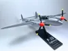
P-38 Lightning 1:48 Scale
Print Profile(2)

Description
About the Aircraft
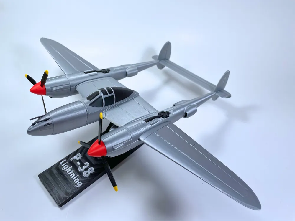
The P-38 Lightning was an American interceptor during World War 2. It was a twin engine heavy fighter that was primarily used as a long range fighter and fighter-bomber. It featured an iconic twin boom design, and about 10,000 aircraft were built. While early jets made the Lightning obsolete after the war, it became popular for use in air racing, and because surviving examples are rare, the P-38 remains a highly valued aircraft today.
About the Model
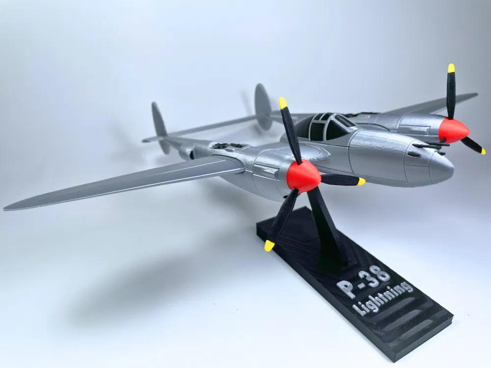
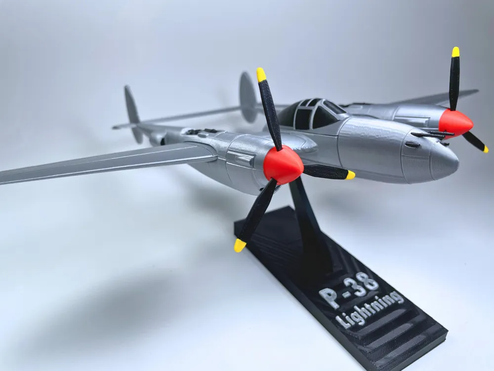
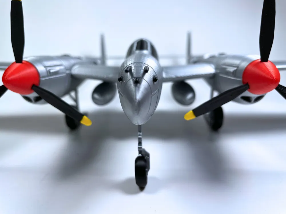
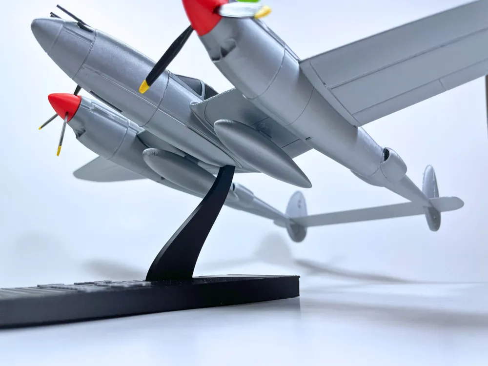
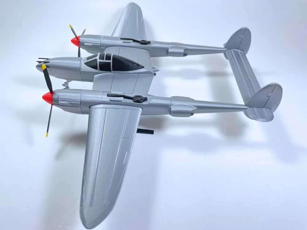
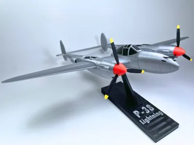
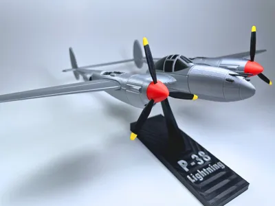
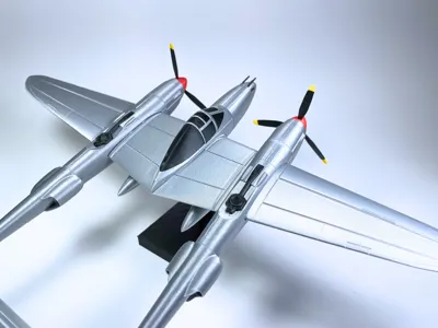
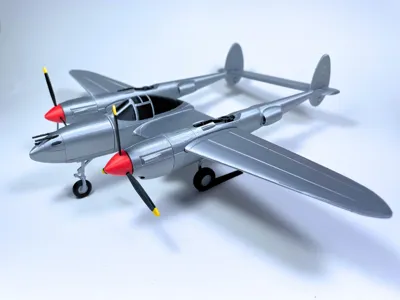
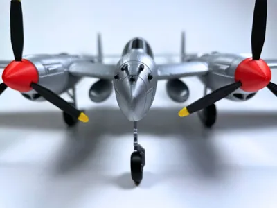
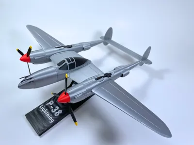
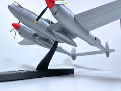
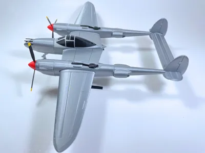
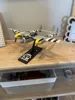
A few months before I designed the Lightning, I designed a 1:48 Scale BF-109. Due to the positive reception of it, I have been motivated to create more 1:48 WW2 aircraft. While the BF-109 features some design choices reminiscent of a kit card model such as flat wings and fuselage halves, this has been changed with the P-38. The P-38 has increased detail quality, and underwent many iterations to improve on the detail and design of the model. The model features removable tricycle landing gear, removable drop tanks, and a stand, which provides an opportunity for display versatility. This model requires glue to assemble, and you can also use sandpaper to modify the fit of components. Before printing, please keep in mind that printer and filament quality has a great impact on the quality outcome, and I urge you to consider this if something goes wrong. I had no issues printing this with Bambu silver, red, yellow, and black filaments on an A1 Mini (Cool Plate) and I used superglue (cyanoacrylate) glue to build the model. Enjoy!
Assembly
Assembly is relatively straightforward, and is facilitated by the use of small cubes for connections. The cubes are not designed to hold the joint by themselves, but are rather for helping to align the components for gluing. All components are labelled in the .3mf file. Before removing them from the plate, ensure that you know which is which.
- Remove the nose and nose midsection from the plate as well as one of the cubes. use the cube to line them up and then apply glue. Let it dry.
- Remove the fuselage main section from the plate as well as another cube and glue it to the nose midsection.
- Remove the cockpit from the plate and glue it onto the top of the fuselage using the connected midsection to help line it up.
- Remove the right engine from the plate, as well the right tail front section. Glue them together, then glue to the rear tail section. Ensure these are all the right side parts. Note: the Right engine can be denoted by the backwards L on the reverse side, and the Right Rear Tail section can be denoted by the seam along the boom that should be on the inside edge and not visible when looking at the aircraft from a side profile. Test fit the Right Tail front section to the fuselage because it's wing connections between the inner and outer wing are different.
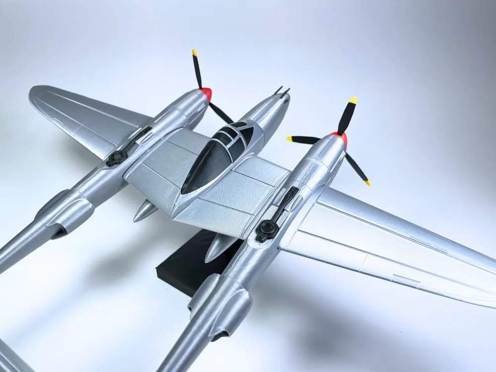
- Repeat the previous step for the left side of the plane. The left engine will have a non-backwards L on the reverse side. IMPORTANT Before gluing the left side to the main fuselage, insert the horizontal stabilizer to both tails as shown in the model photos, with the control surfaces to the rear edge.
- Glue the tails to the main fuselage.
- Connect a turbosupercharger to the top of each tail section.
- Connect the outer wings to the tails. The wings should have a positive dihedral and you can use this to determine which is right or left if they have been mixed up.
- Assemble the propellers by using a spinner and 3 blades connect a prop shaft into each engine. Put the blades into the slots in the spinner and glue them in so they cannot move individually. Repeat again for the propeller on the other side.
- Connect the propellers into the prop shafts. If you want them to be spinnable, don't use glue.
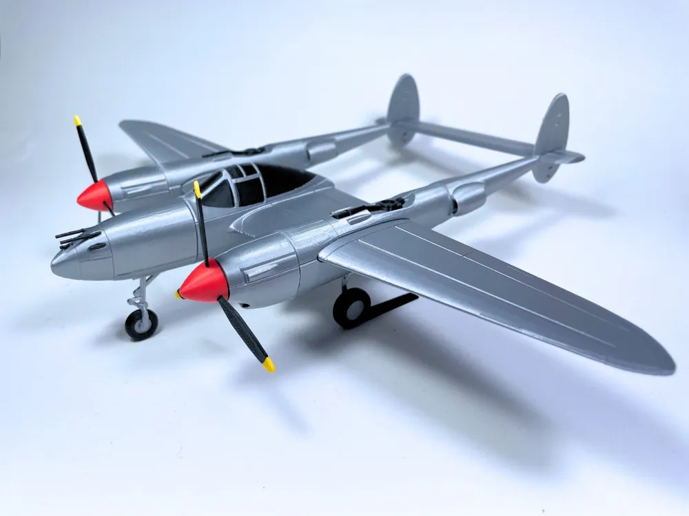
- Connect the main gear wheels into each main gear using the tooth and slot on the parts to orient them correctly. The main gears are identical so it doesn't matter which tire goes where. The main gears have a design which allows them to stabilize even though the center of mass is behind them. Insert them so this extends towards the tail as shown in the model photos.
- Assemble the nose gear by putting the tire onto the gear and then connecting it into the underside of the fuselage. Use the face of a knife blade or another flat object to lay across the mount for the gear and push it into the slot. If you want it to be removable, don't use glue.
- Connect the main gear into the slots on the underside of each tail boom.
- Optionally, print and assemble the stand and the drop tanks, which are included in a separate profile. Stay tuned, because I may make more accessories such as tanks, bombs, and rockets that will be universally compatible with this and future 1:48 models.
- If the nose lifts up when setting the aircraft down in its landed configuration, slightly bend the main gears forward. This places more leverage on the stabilizers and will balance the aircraft. Contact me if you have problems. Enjoy printing the model, and I'd love to hear feedback or see makes!
License

You shall not share, sub-license, sell, rent, host, transfer, or distribute in any way the digital or 3D printed versions of this object, nor any other derivative work of this object in its digital or physical format (including - but not limited to - remixes of this object, and hosting on other digital platforms). The objects may not be used without permission in any way whatsoever in which you charge money, or collect fees.


Comment & Rating (24)