
Generate Accurate 3D Models from Calibrated Photos
Print Profile(1)
Description
I often create electronic enclosures that include assemblies that I don't have an STL or STEP file for. I tried various Android 3D scanner apps and while suitable for artistic objects they didn't seem to be dimensionally accurate or do a good job or isolating the object that I wanted to scan. I had good success with Chat GPT creating plausible models that isolated the object but it left the question of obtaining accurate dimensions.
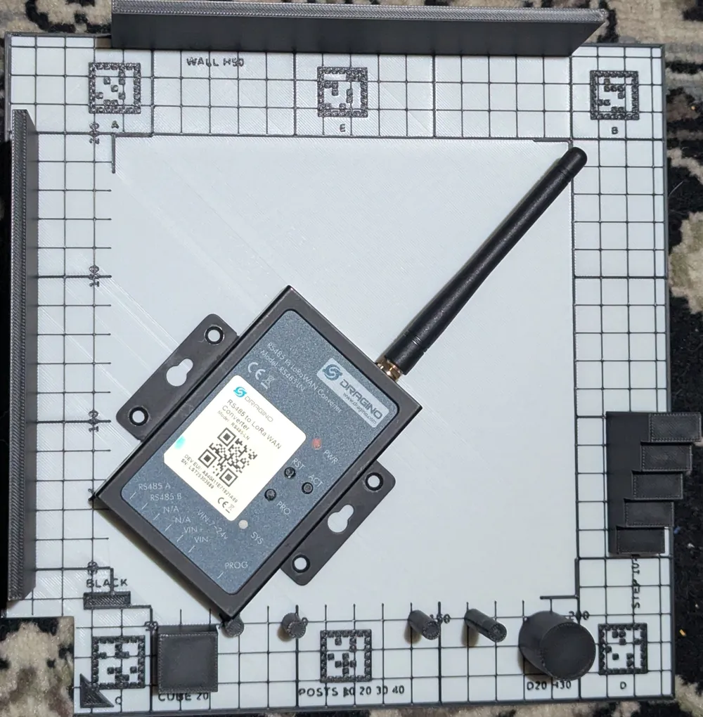
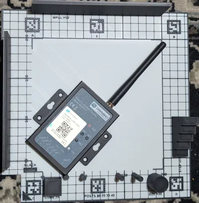
This model can be used to solve that and seems to offer accuracy of 1-2mm over the total scanning area even using cell phone photos with fairly average lighting. Below is a prompt you can paste into Chat GPT along with attaching a series of photos. Taking one from the top and one from each of the four sides pointing down at 45 degrees works well, so it's also less tedious than a lot of 3D scanning apps.
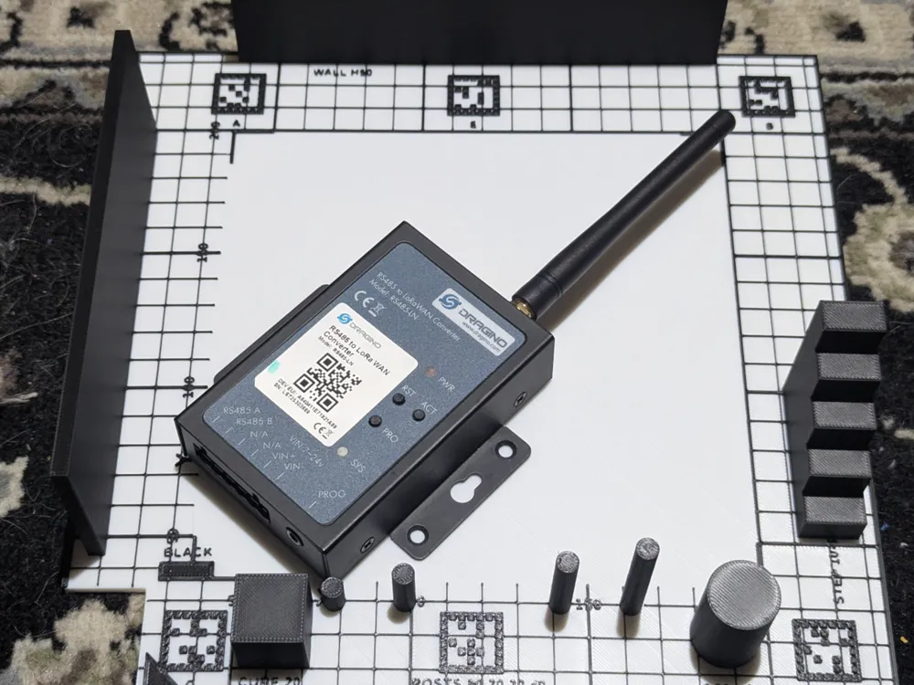
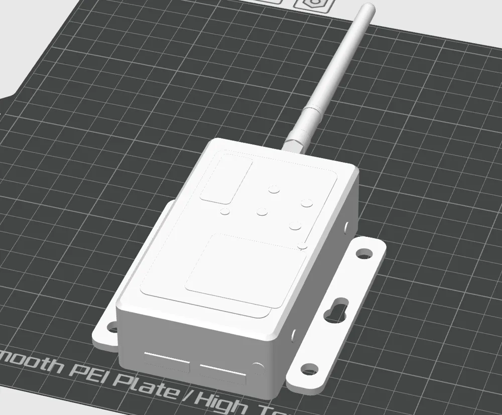
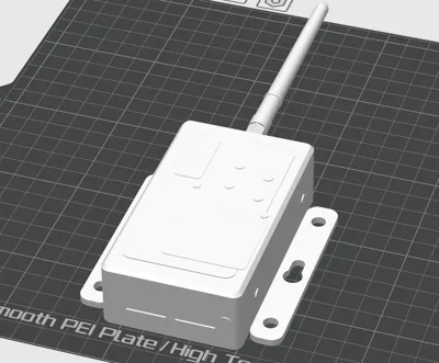
The example photos shows one of the objects I was scanning and the nice clean output it produced when imported into Bambu Studio. Following is the prompt to paste into Chat GPT:
---
I have attached one or more photos of a small object placed on a known 3D calibration stage. Please analyze the image and create a dimensionally plausible STL model of the object.
Calibration stage details:
- The calibration stage has an outer footprint of 235 mm x 235 mm.
- The front-left corner has a relief notch approximately 24 mm x 34 mm.
- The relief notch is only for printer clearance and should not be treated as part of the object.
- The base is white or light-coloured.
- All raised markings and vertical calibration features are black.
- The stage uses a coordinate system where:
- The front-left corner of the full 235 mm x 235 mm outline is the origin.
- X increases left to right.
- Y increases from the front of the plate toward the rear.
- Z is vertical.
- The horizontal grid spacing is 10 mm.
- Major grid lines occur every 50 mm.
- The central clear detect zone is approximately 164 mm x 164 mm.
- The detect zone starts at approximately X = 36 mm, Y = 36 mm.
- The detect zone ends at approximately X = 200 mm, Y = 200 mm.
- The grid is mostly interrupted through the detect zone so the object is easier to identify.
- The detect zone has corner-bracket markings rather than a full border.
- There is no title text across the top middle of the plate.
Fiducial/reference markers:
- There are six black visual fiducial markers around the perimeter.
- They are labelled A, B, C, D, E, and F.
- A is near the rear-left perimeter.
- B is near the rear-right perimeter.
- C is near the front-left perimeter, to the right of the relief notch.
- D is near the front-right perimeter.
- E is near the rear-centre perimeter.
- F is near the front-centre perimeter.
- Use these markers to help infer camera perspective, rotation, scale, and plate orientation.
- These are visual pseudo-fiducials, not guaranteed ArUco or AprilTag codes.
Vertical calibration features:
- The stage has a plain black L-shaped vertical reference wall.
- The L-wall is 50 mm high.
- The L-wall does not have fine printed height lines.
- The stage has a black step tower with known step heights of 10, 20, 30, 40, and 50 mm.
- The stage has black height posts of 10, 20, 30, and 40 mm.
- The stage has a black 20 mm x 20 mm x 20 mm reference cube.
- The stage has a black reference cylinder that is 20 mm in diameter and 30 mm high.
- Use the known height objects, silhouettes, top faces, and visible perspective cues as dimensional references.
- Do not include any calibration-stage features in the final object model.
Task:
1. Identify the calibration plate, grid, relief notch, fiducials, detect zone, and vertical reference features.
2. Estimate the camera perspective and scale using the 235 mm plate, 10 mm grid, 50 mm major lines, fiducials, and known vertical features.
3. Segment the object from the calibration stage.
4. Estimate the object's true length, width, height, and major feature dimensions in millimetres.
5. Reconstruct only the object, not the calibration stage.
6. Create a clean, watertight, 3D-printable model.
7. Generate the model as parametric OpenSCAD code first.
8. Then provide or export an STL file if possible.
9. Preserve visible bevels, holes, curves, raised details, recesses, and symmetry.
10. Do not model shadows, printed grid lines, fiducials, labels, or calibration marks as part of the object.
11. Where hidden geometry is not visible, make reasonable assumptions and clearly list them.
12. Include a dimensional summary with estimated overall length, width, height, and any uncertain dimensions.
Important:
- The photo may be taken at approximately a 45-degree angle.
- Use the black vertical features to estimate Z height.
- Use the white base and black raised grid/fiducials for scale and perspective.
- If the photo is insufficient for an accurate STL, explain what additional views are needed and still provide the best approximate model possible.
- Multiple calibrated views are preferred: front 45-degree, rear/opposite 45-degree, top-down, and side view.
- Do not assume the relief notch is part of the object or part of the 235 mm square measurement; it is simply a missing corner for printer clearance.
License

You shall not share, sub-license, sell, rent, host, transfer, or distribute in any way the digital or 3D printed versions of this object, nor any other derivative work of this object in its digital or physical format (including - but not limited to - remixes of this object, and hosting on other digital platforms). The objects may not be used without permission in any way whatsoever in which you charge money, or collect fees.


Comment & Rating (1)