
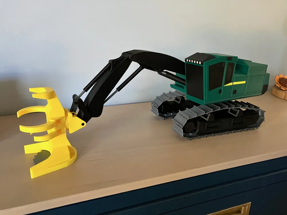
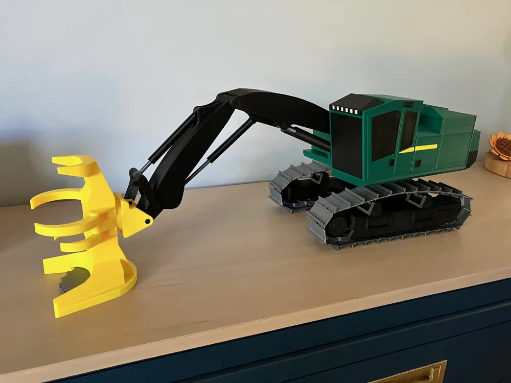
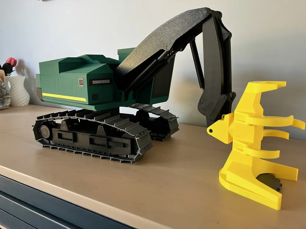
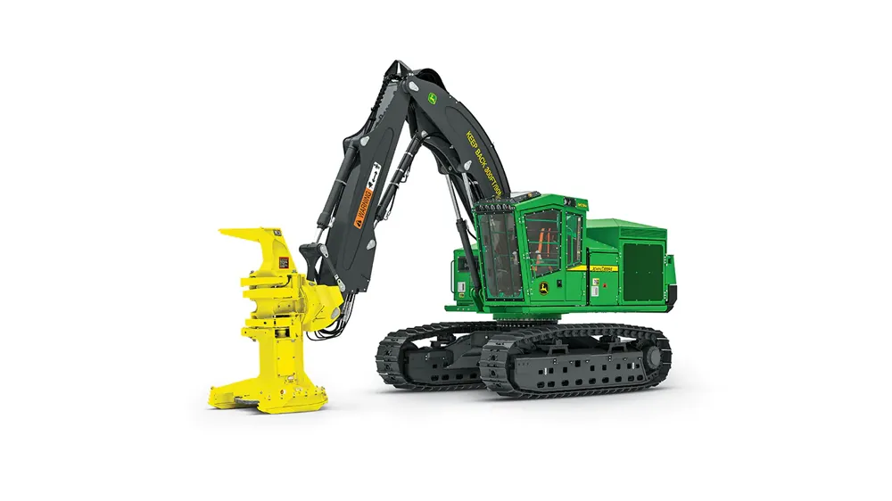
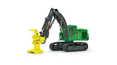
John Deere 903m Buncher
Print Profile(1)
Bill of Materials





Description
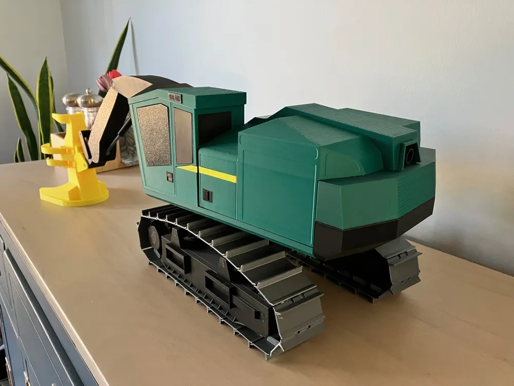
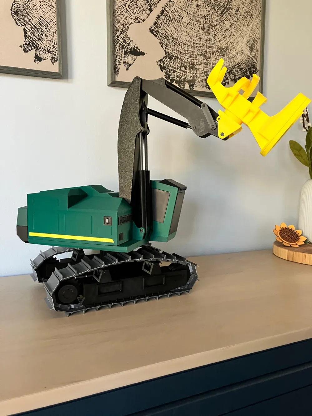
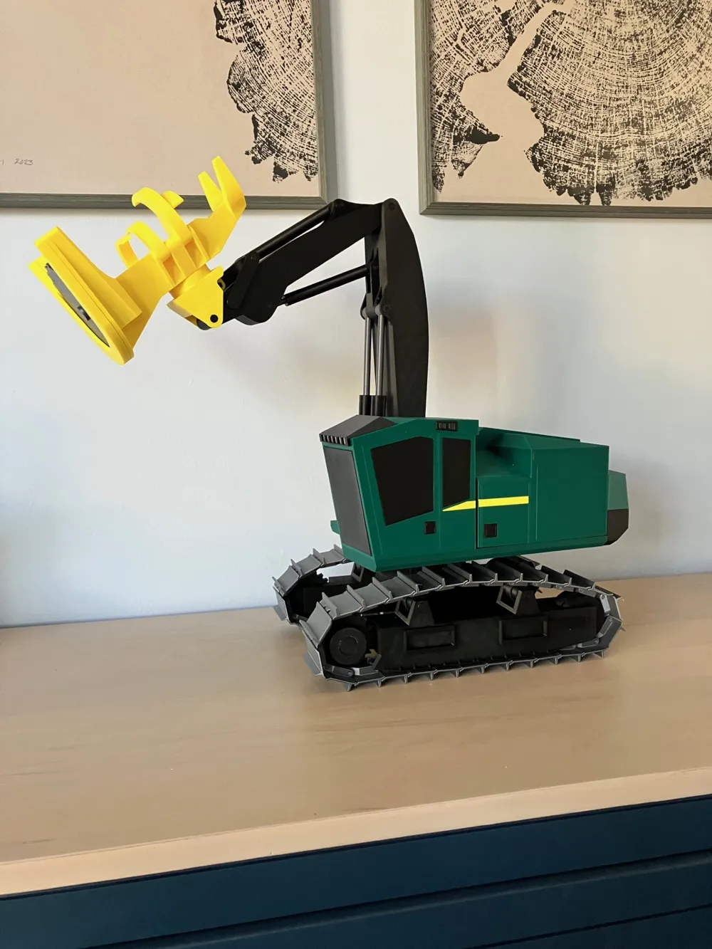
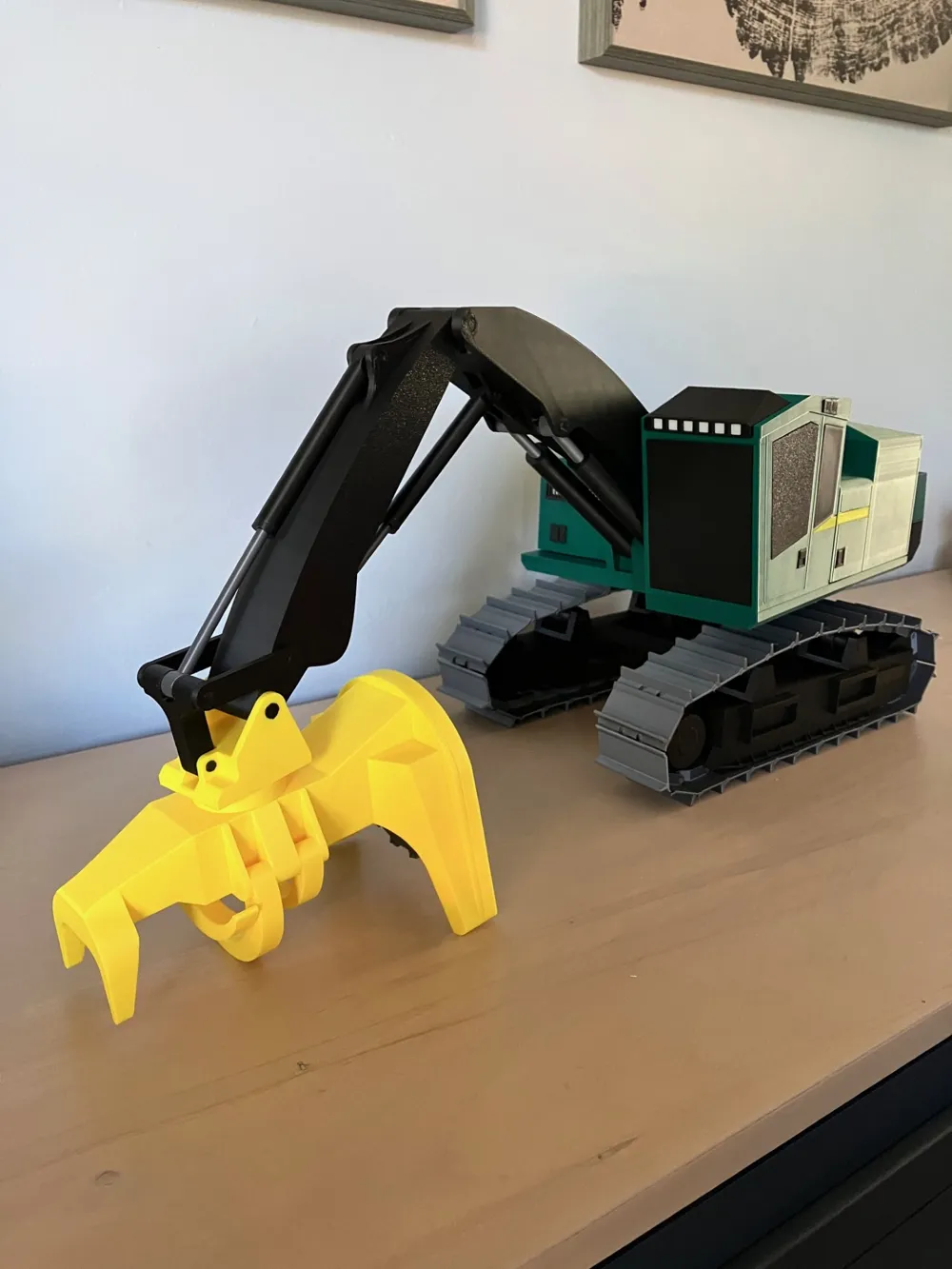
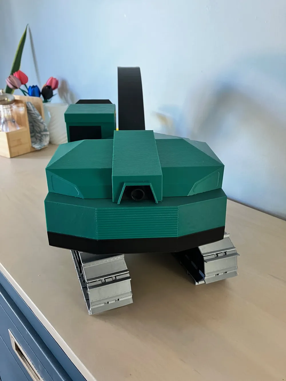
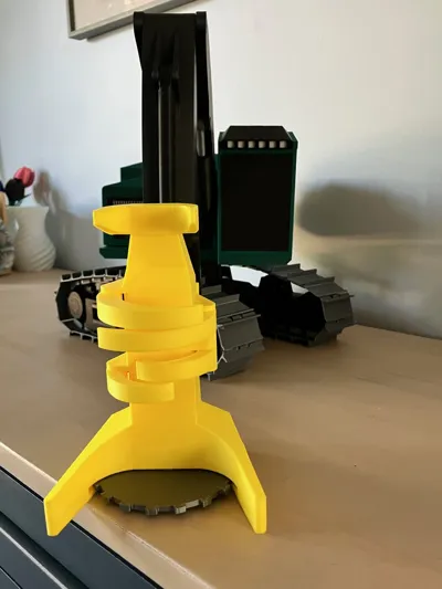
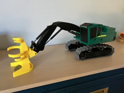
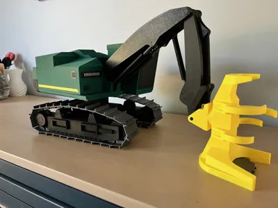
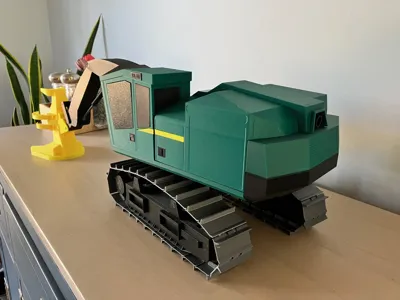
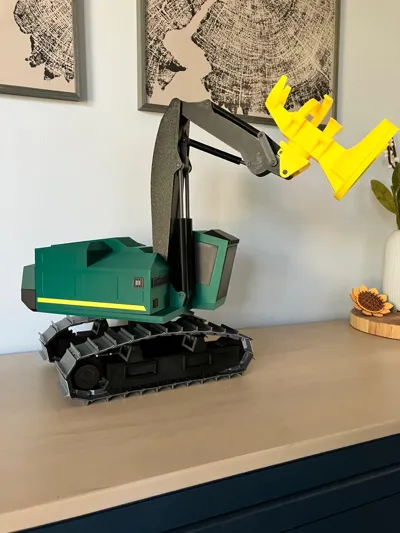
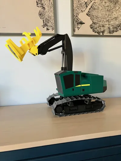
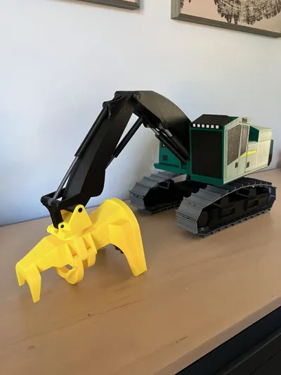
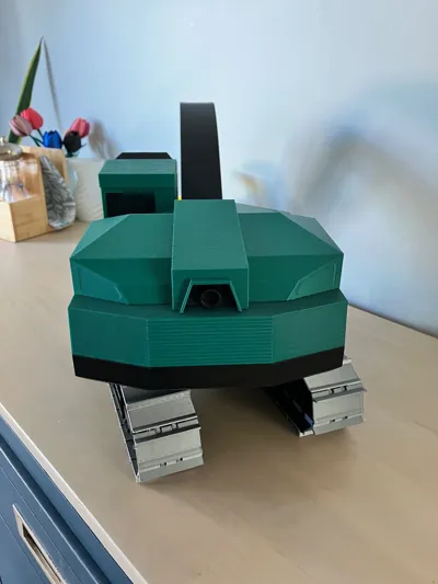
John Deere 903m tracked feller buncher model 1/16th scale. This model requires no extra parts to assemble other than glue. I recommend loctite 401 instant adhesive. All the fasteners are printed pins that are friction fit. This is a Large realistic model that the components turn move like the real machine! The model can be printed without an ams If you don't use a support interface material.
This is my first big project that I have made, I probably have over 150 hours designing and building this model so please feel free to boost this model to show your support.
Boost Me (for free)
As far as building instructions the model is fairly straight forward. Some parts may require some slight trimming to get proper fitment.
I started by gluing the details on like the windows, lights, door handles, stripes, and exhaust, to the cab and the main body.
Assemble and install the boom, and linkage using the appropriate pins. The pins should push into place and should not need any glue. I found it helpful to use a pair of pliers like knipex plier wrench to help push the pins in.
Glue the 3 sections of the undercarriage/ track frames together.
Assemble the undercarriage - install top two rollers the idler and the sprocket on each side. These items are held in with pins and should not require glue.
Assemble the track links 26 for each side. Track pins just push in through each link and should also not require any glue. Lay the track around the sprocket and idler rollers on the assembled track frame and push the final pin in joining the track together.
Assemble the cylinders. Take the cylinder rod and install the “Gland” onto it, then fit and glue the piston to the end of the rod. Finally take the barrel of the cylinder and insert the rod and piston into the barrel and carefully glue the “gland” to the barrel. *Make sure cylinders move after gluing.
Install the cylinders on to boom in the appropriate places.
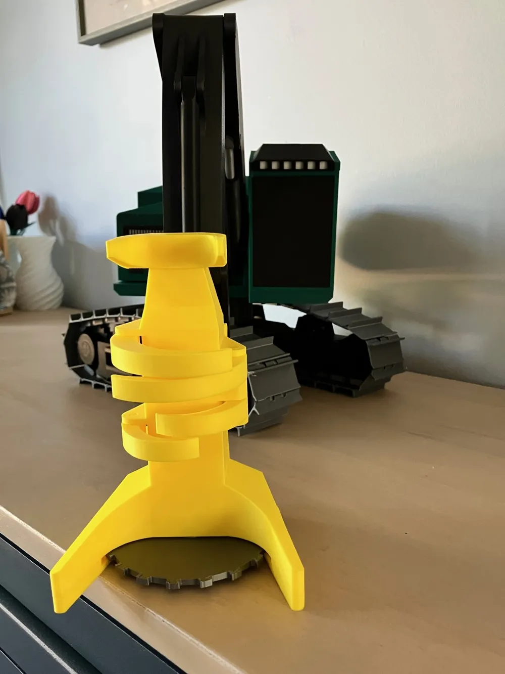
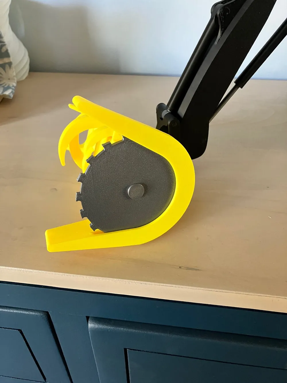
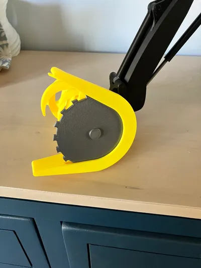
Assemble the Saw head. The larger grapple arms should be installed on the top of the saw head and the smaller ones go on the bottom. The saw is installed on the bottom and held on with a pin then install the lower saw guard, I used a small amount of glue to help keep the saw guard on the bottom.
Finally install the saw head on the boom, and assemble the remaining components. The hood, cab and counter weight all have pins to locate them to the correct location.
Thanks for the support and Happy Printing!
License

You may create derivative works based on this object, provided that all such derivative works are published exclusively on the MakerWorld platform and include proper attribution to the original creator. You may not share, upload, host, distribute, or publish this object—or any derivative work of this object—on any other digital platform, marketplace, or distribution channel. Commercial use of this object and any derivative works is strictly prohibited. This includes, but is not limited to, selling, renting, sublicensing, or using the object in any context in which you receive monetary compensation or other financial benefits.


Comment & Rating (0)