
P2S Exhaust Manifold with Filter for Bambu Exhaust Kit
Print Profile(1)
Description
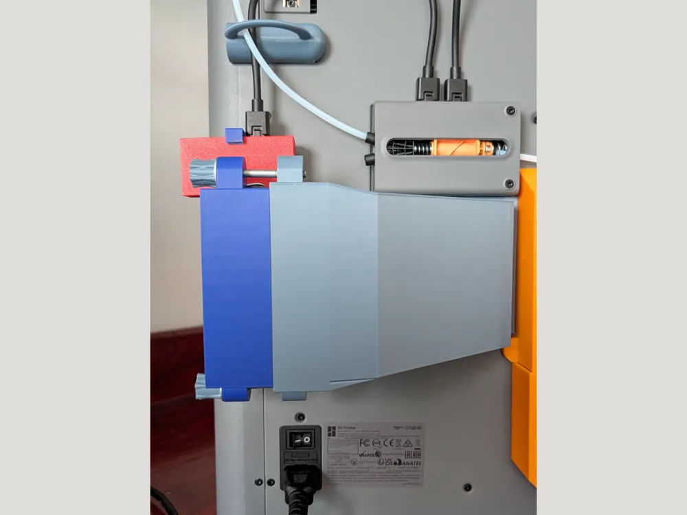
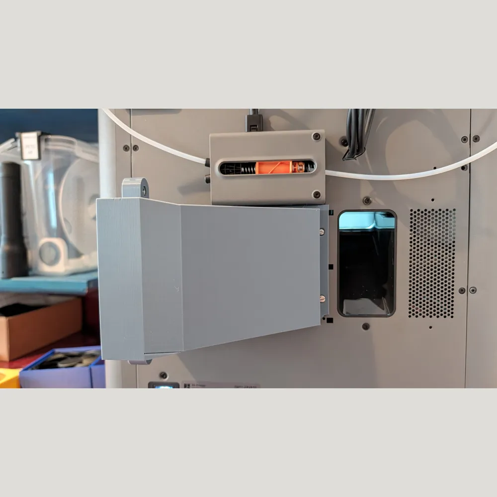
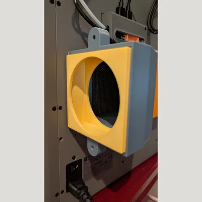
Manifold with filter for Bambu Exhaust Kit for P2S
Fan duct (100 x 100 mm) for the Bambu exhaust kit rotated 90° to the right with filter insert. (Carbon+HEPA)
Required Material:
- Bambu Exhaust Kit for P2S
- Metric screws 2 pcs M5x80mm + nuts
- Self-tapping screws 4 pcs 2.5x10mm (or longer)
- Filter mats HEPA (5-15mm) and activated carbon (5-15mm) each approx. 100x100mm
- optionally double-sided tape and some foam rubber (1x2 cm)
- Adhesive
Everything is printed in PETG without supports
Task:
Since the printer stands on a standard table 60cm deep, it has to be close to the wall. The original exhaust kit housing blows directly to the back (thus against the wall). This is very unfavorable. Many models often sit on top of the original housing, which wastes too much space for me. I have therefore designed my own model. Based on the fan from the Bambu Exhaust Kit for the P2S.
The exhaust air should also be filtered, as I don't have an exhaust duct in the room.
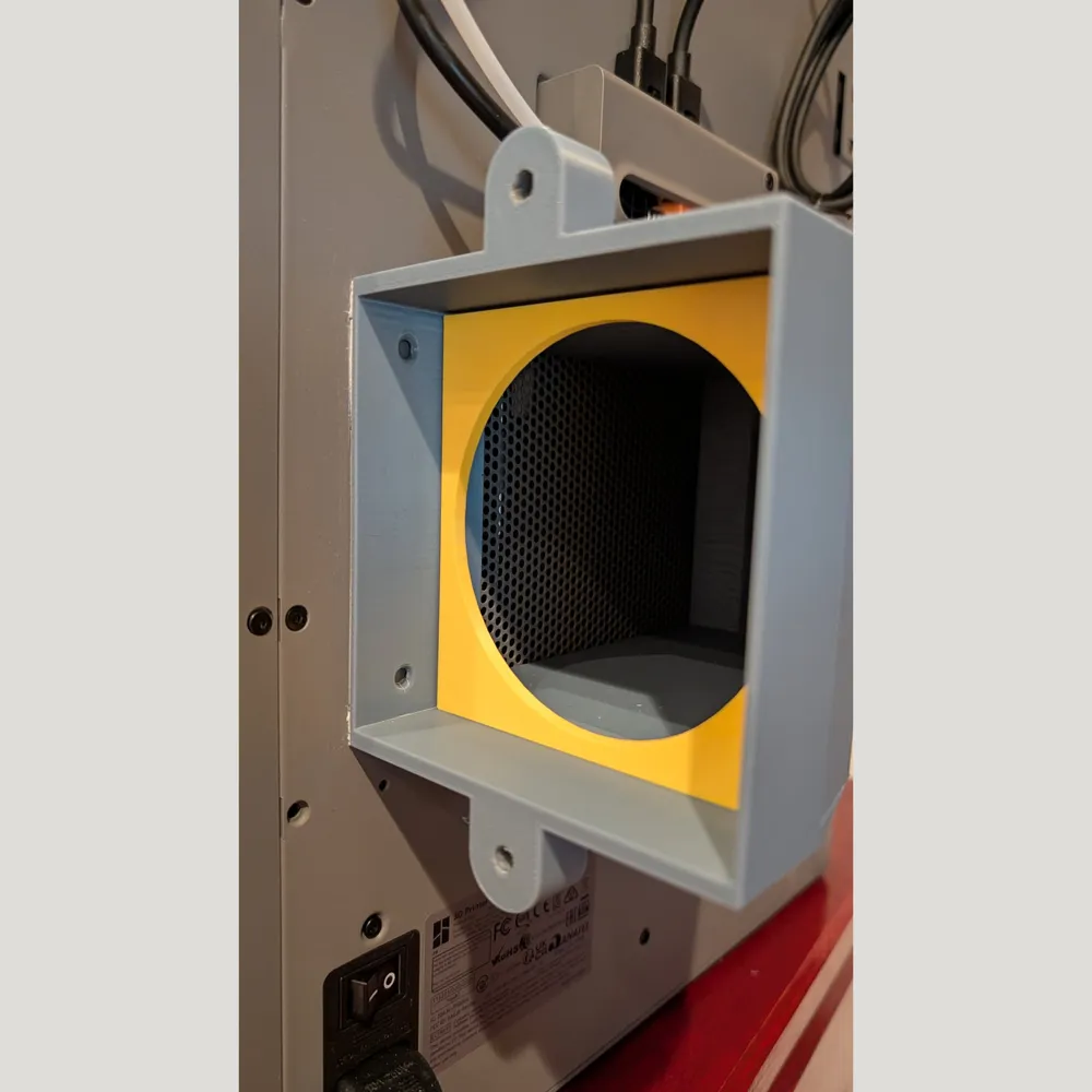
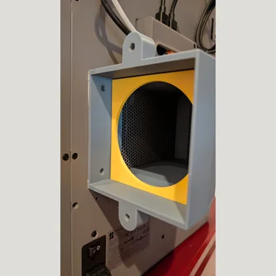
My filters are mats (5-15mm thick); I cut them into small 100x100mm plates and place them in the yellow filter box.
Order = HEPA, Carbon, HEPA filter mat.
The mats should not be compressed, only lie loosely on top of each other!
The filter box can be created in two sizes as required.
a) Filter module (25mm) + plate (3mm) for approx. 20mm filter thickness or
b) Filter module (25mm) + filter module extension (15mm) for approx. 35mm filter mat thickness.
My filter mats are now approximately 30mm thick in total.
Assembly:
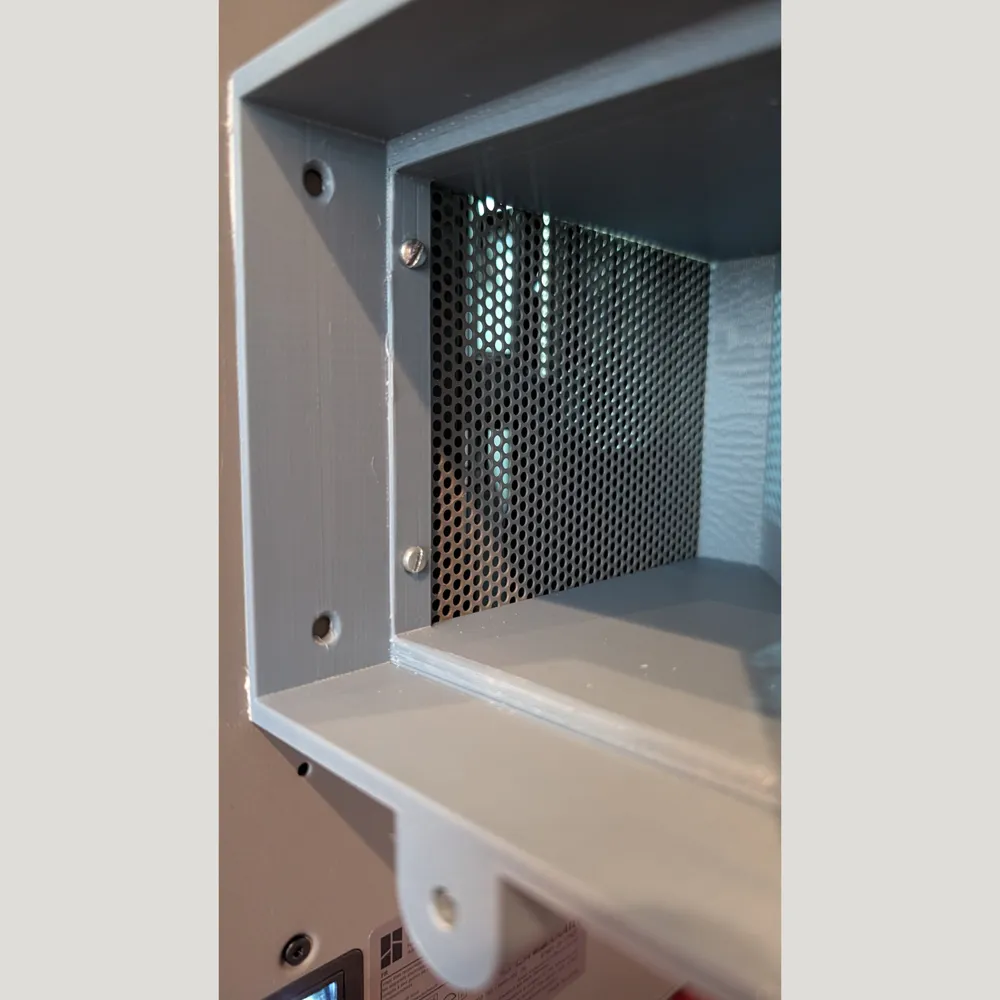
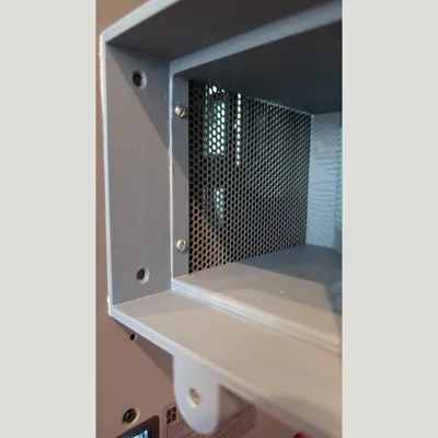
1) Two M5 nuts go into the two ears of the manifold (gray), where they clamp firmly and do not need to be further secured.
2) Press two M5x 80mm screws (hex head) into the knurled nuts; they hold the individual modules together.
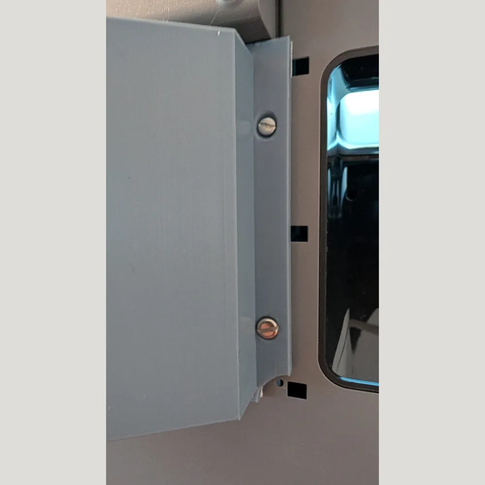
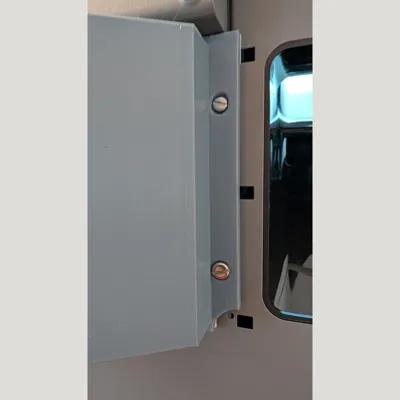
3) The manifold (gray) is screwed directly to the back wall with 4 self-tapping screws; simply turn the self-tapping screws into the small holes of the fan cutout. I also used double-sided tape, but it also holds without it. This means no holes need to be drilled.
The manifold is generally not removed again; the fan and filter are inserted and held by two knurled screws.
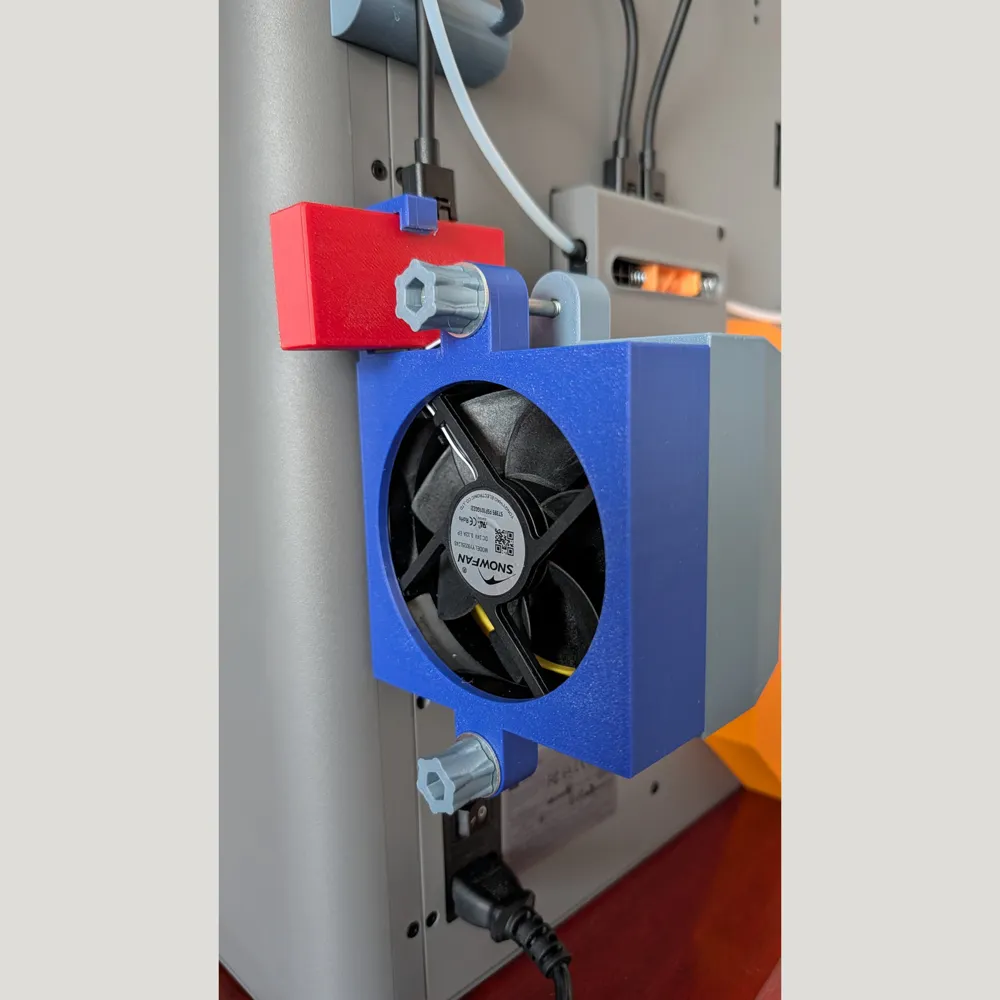
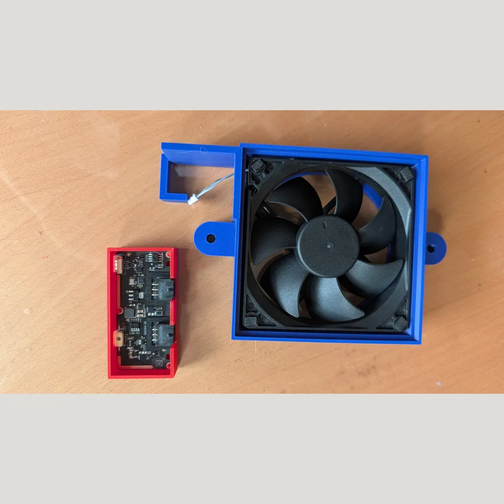
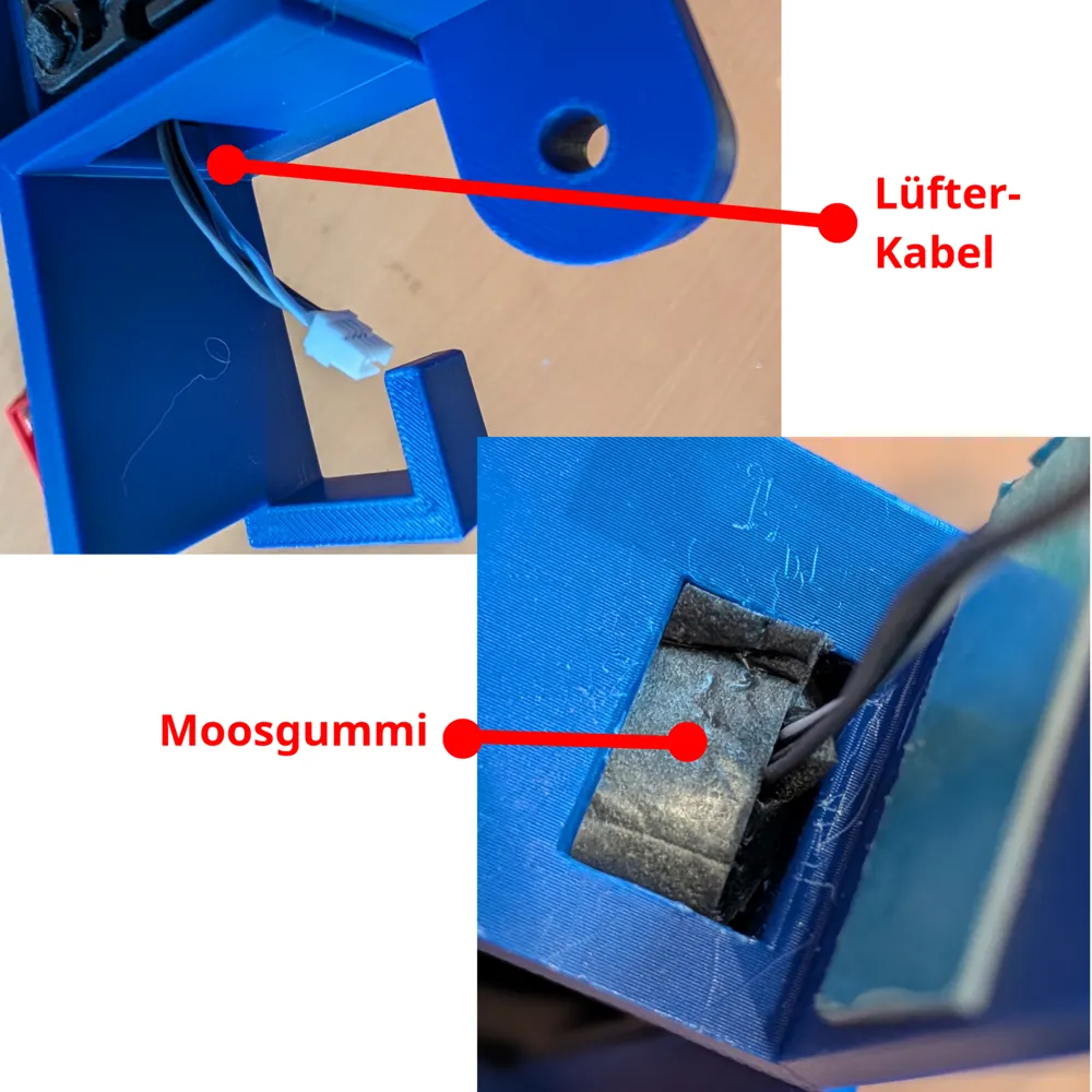
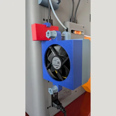
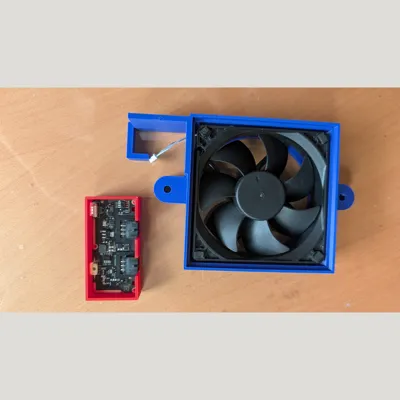
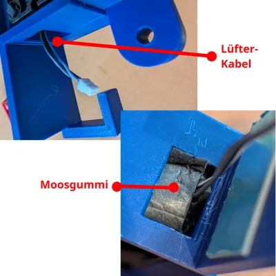
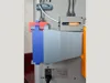
4) Insert the fan into the fan module (blue) (let the cable protrude from the opening at the top). Due to the fan's seal, the fan clamps into the module without screws. Seal the cable opening with some foam rubber. (see photo)
IMPORTANT: INSERT FAN WITH LABEL FACING OUTWARDS (visible from outside)
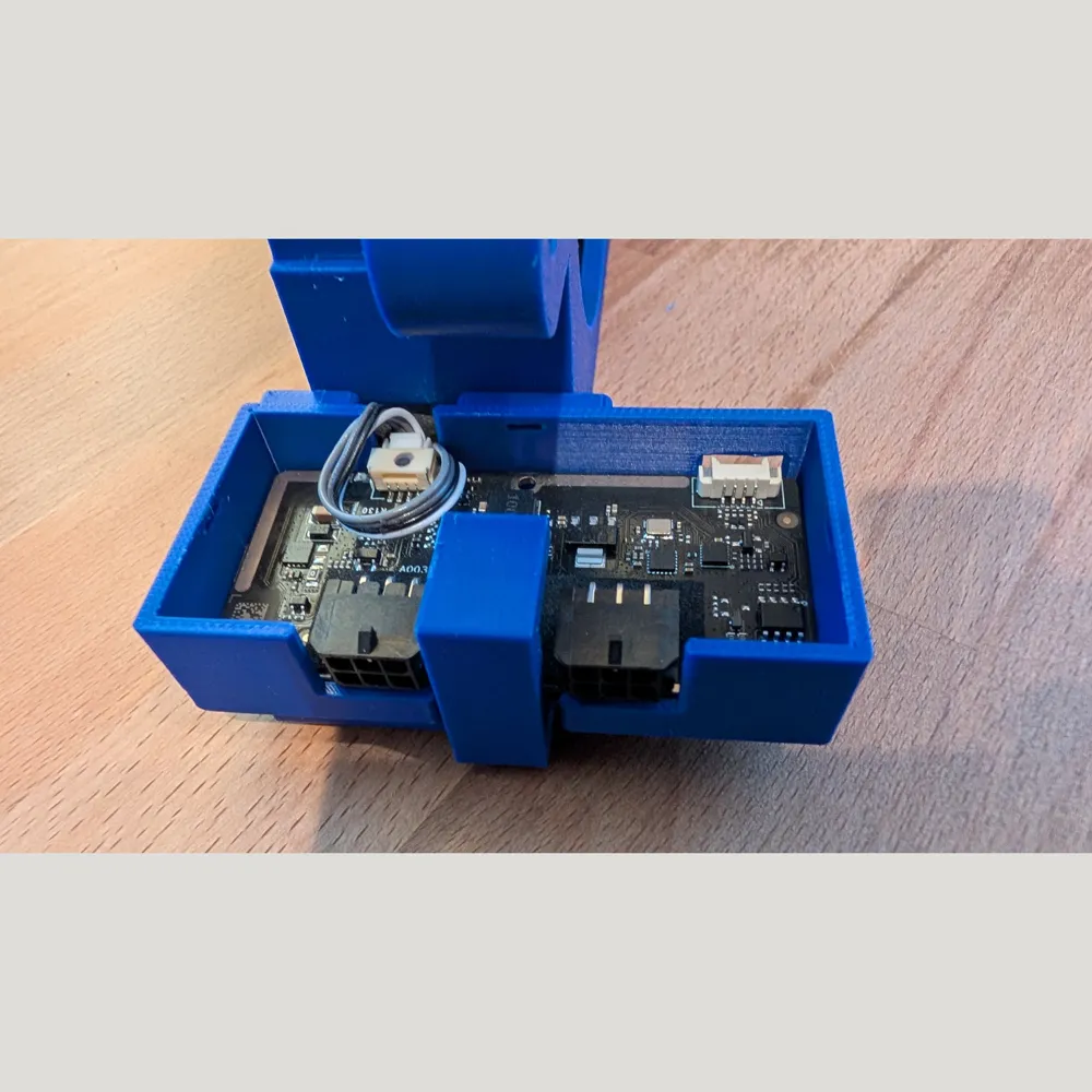
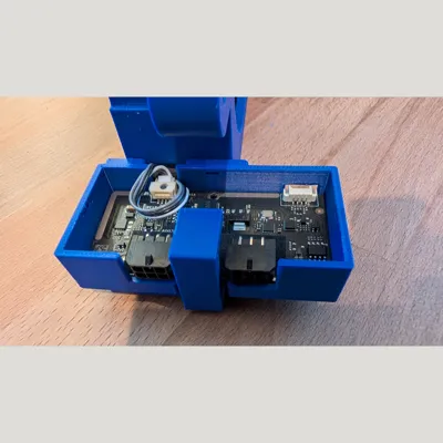
5) Press the fan circuit board into the circuit board housing (sometimes red, sometimes blue in the photo) and plug the fan cable into the circuit board.
Close the box completely. Caution: the lid will no longer fit after gluing in the module!
I initially wanted to use the finished model "Circuit Board Housing" from MakerWorld, but the cable openings were a bit small. My housing is a remix of it, with large openings to better insert the fan cable. However, if you already have it, you can use it here as well. Therefore, there is a red and a blue circuit board housing in the photos. I have tried both.
6) Now thread the entire circuit board housing onto the bracket of the fan module (blue) and glue it. (see photo) Carefully "hide" the cable beforehand. Once the fan is attached with the circuit board housing in the fan module, this unit will not be separated again during further use.
7) The filter mats go into the filter module (yellow), order: HEPA - Activated Carbon - HEPA, depending on the thickness of the mats.
Assembly:
The filter box (yellow) consists of two parts, the filter module (25mm) and
a) the thin plate (3mm) or
b) the extension module (15mm).
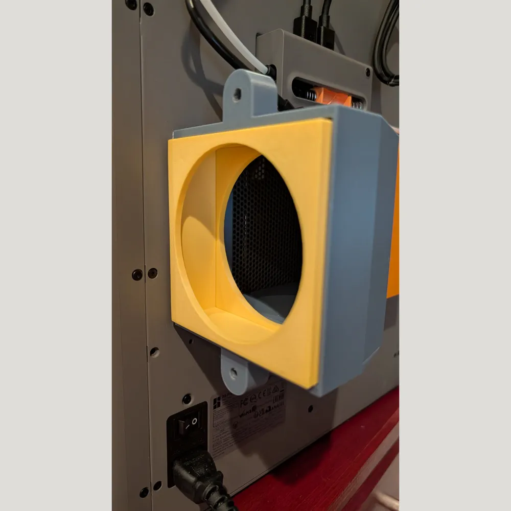
The thin plate (3mm) or the extension module (15mm) go into the manifold first, then the filter module (25mm). The entire yellow filter box then protrudes approx. 5mm from the manifold.
If desired, the filter box can be fitted with the filter mats and then secured with adhesive tape. I did that at the beginning too, but it's not necessary with a little practice. Once the entire filter box is in the manifold, nothing will slip anymore.
Afterwards, the fan module (blue) is plugged on (cuff onto the filter box), with the circuit board pointing upwards.
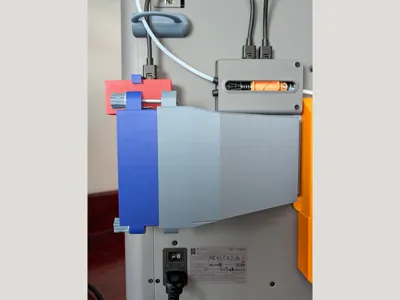
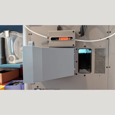
If the thin plate is used in the filter box, the entire filter box disappears after assembly and is no longer visible from the outside (as in the photo). If the extension module is used, approximately 10mm will still protrude.
Now insert the two knurled screws and tighten them slightly, plug in the 6-pin bus cable, and everything is ready.
Now the room ventilation can be used in the software.
Have fun with it.
License



Comment & Rating (0)