
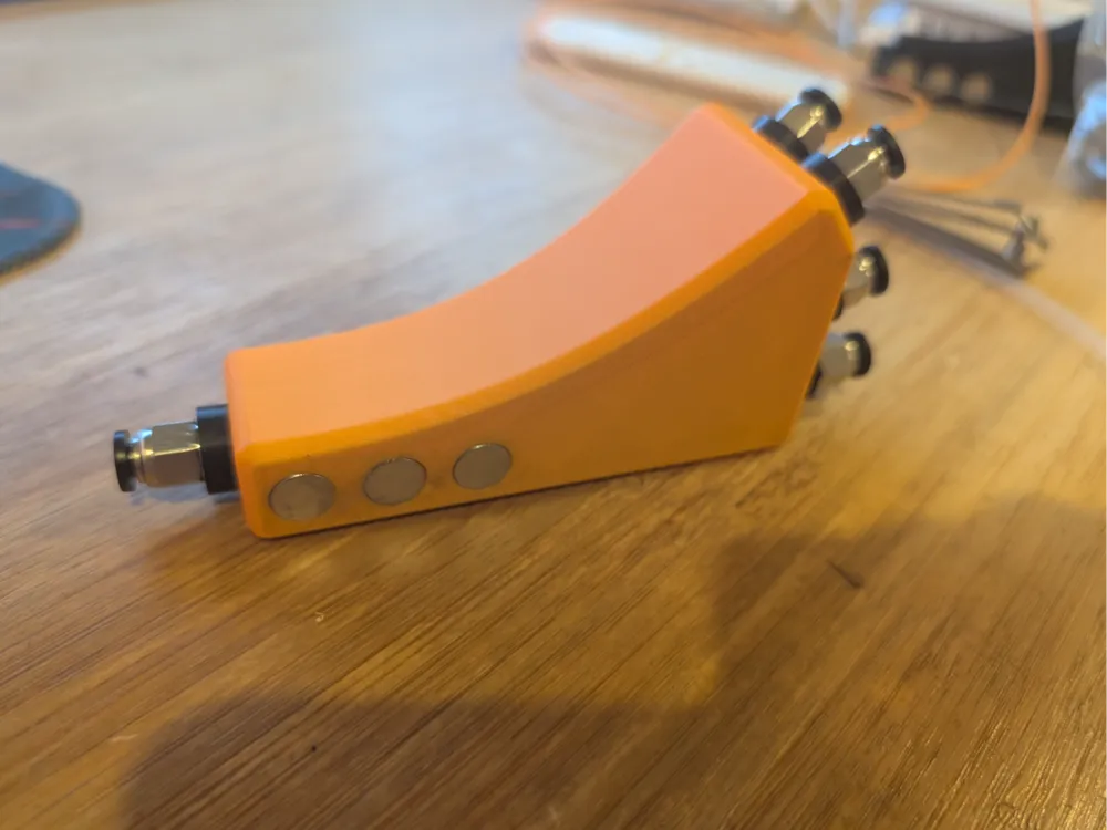
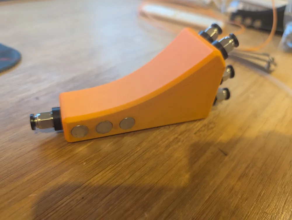
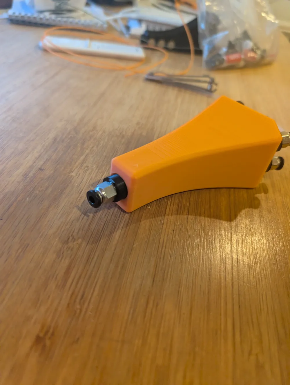
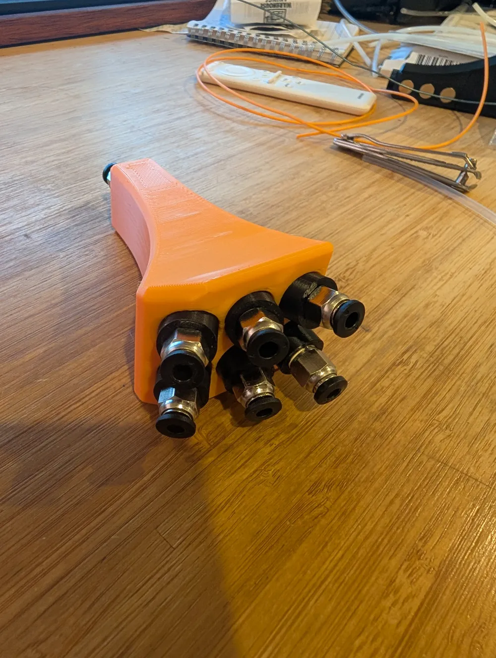
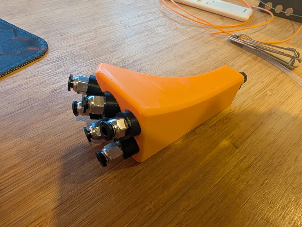
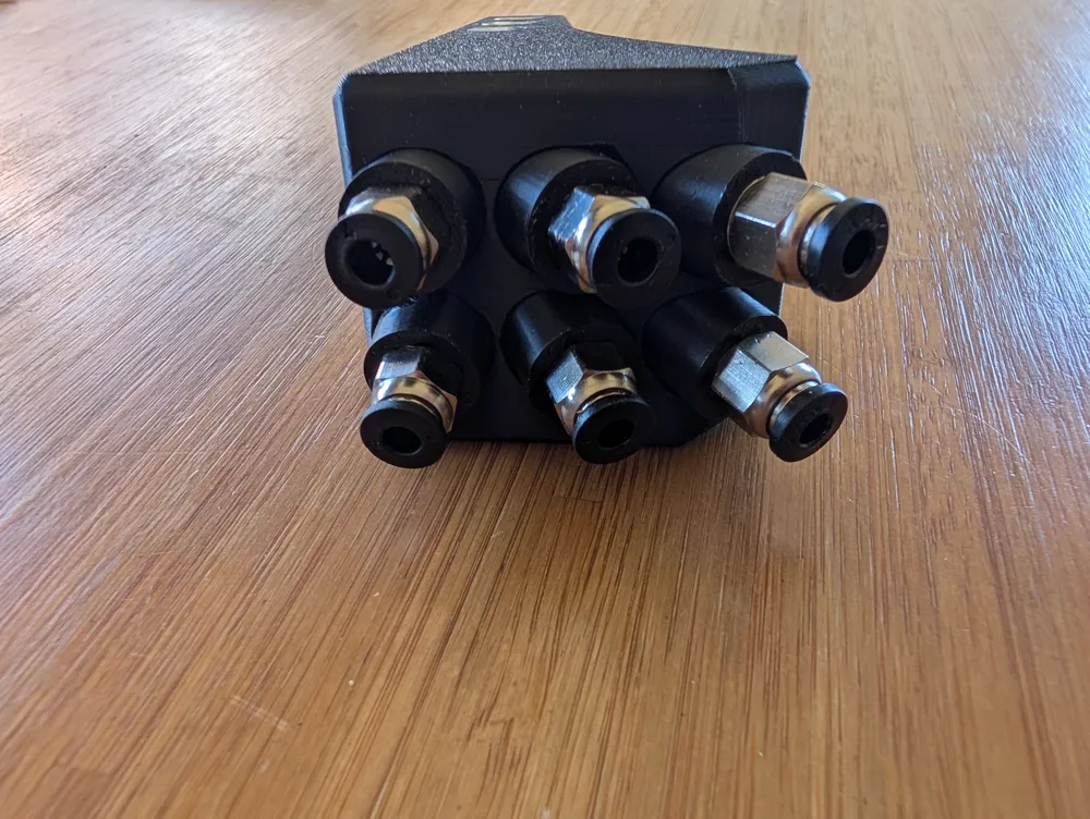
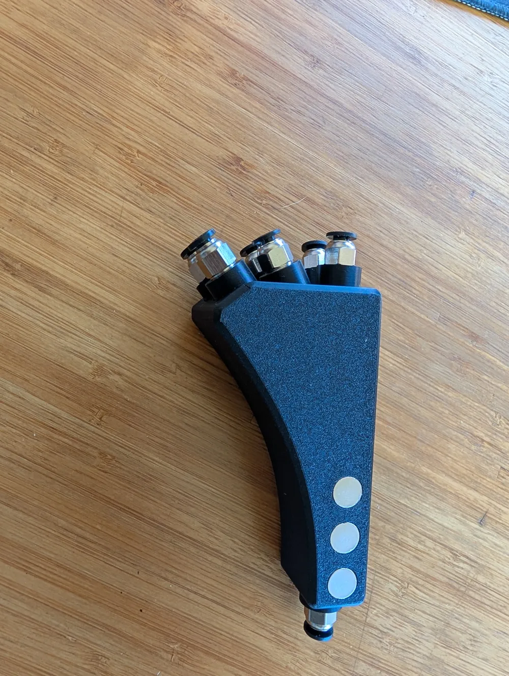
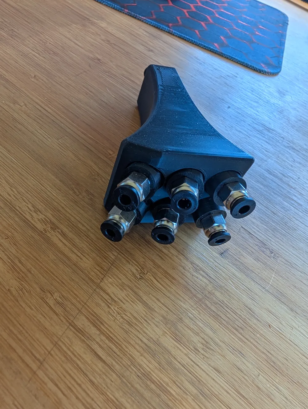
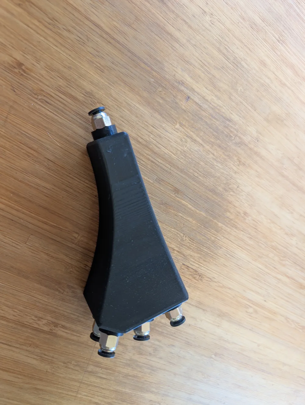
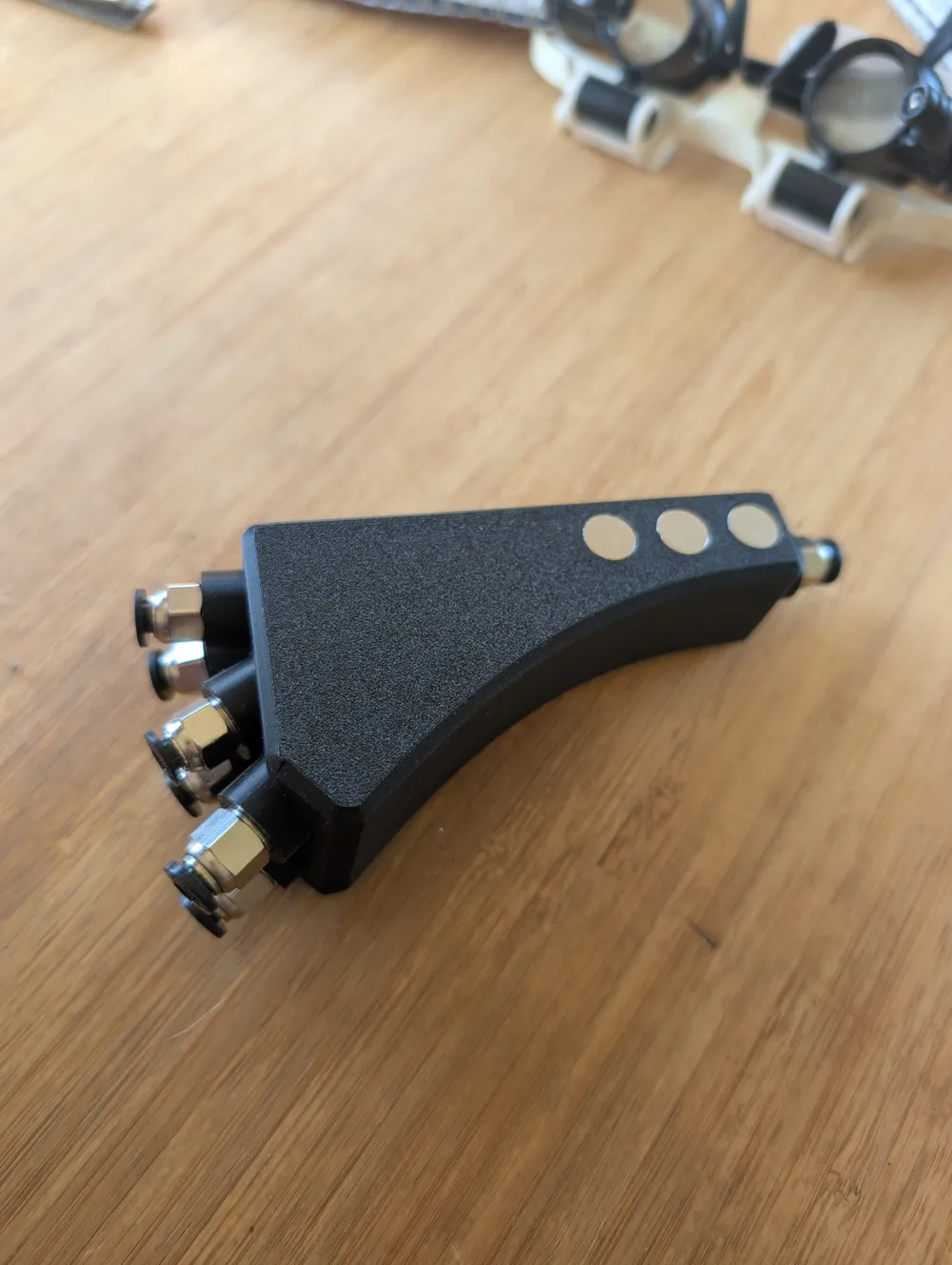
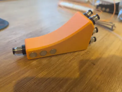
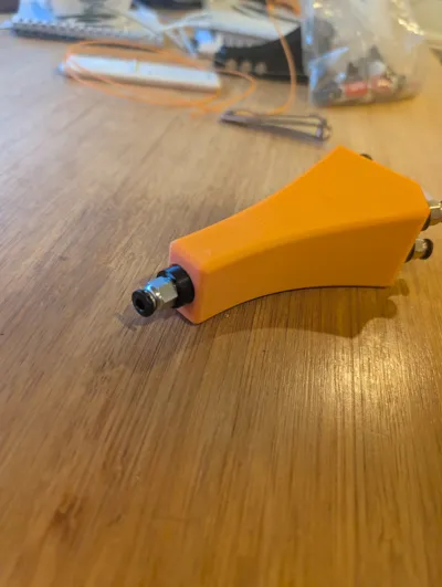
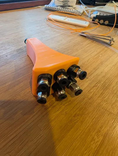
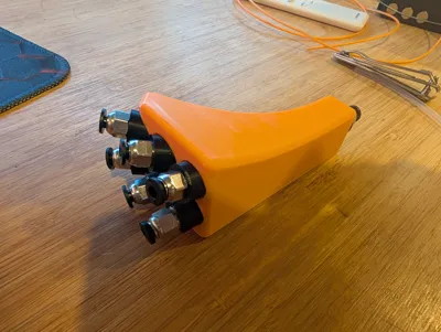
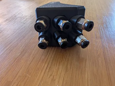
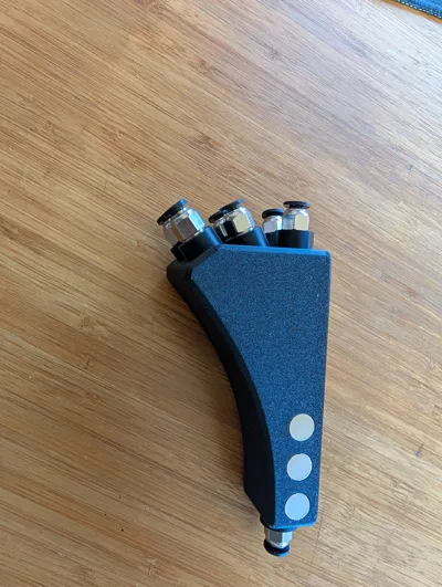
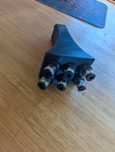
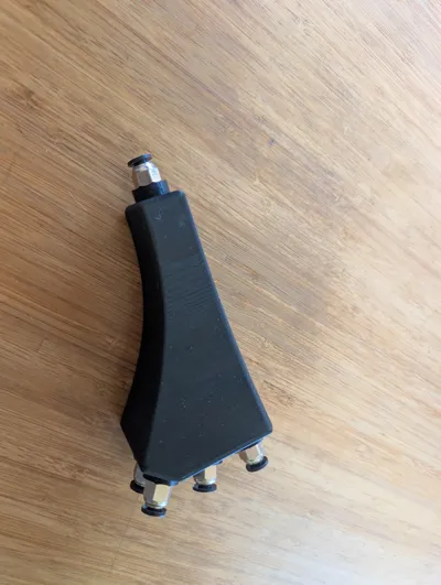
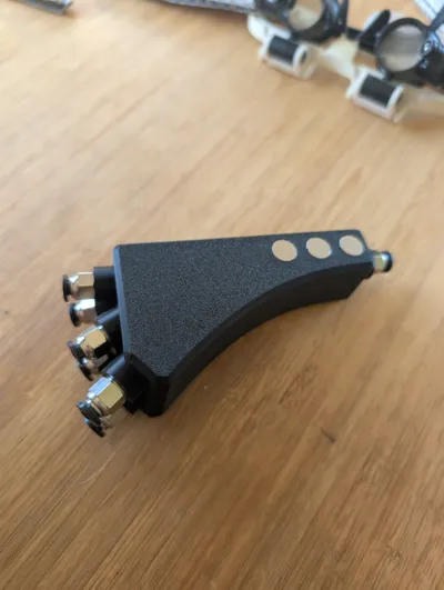
6/1 PTFE splitter, smooth
Print Profile(1)
Description
Feel free to share/remix/commercialize
I recommend Onshape. I have no clue what I am doing but I am getting results.
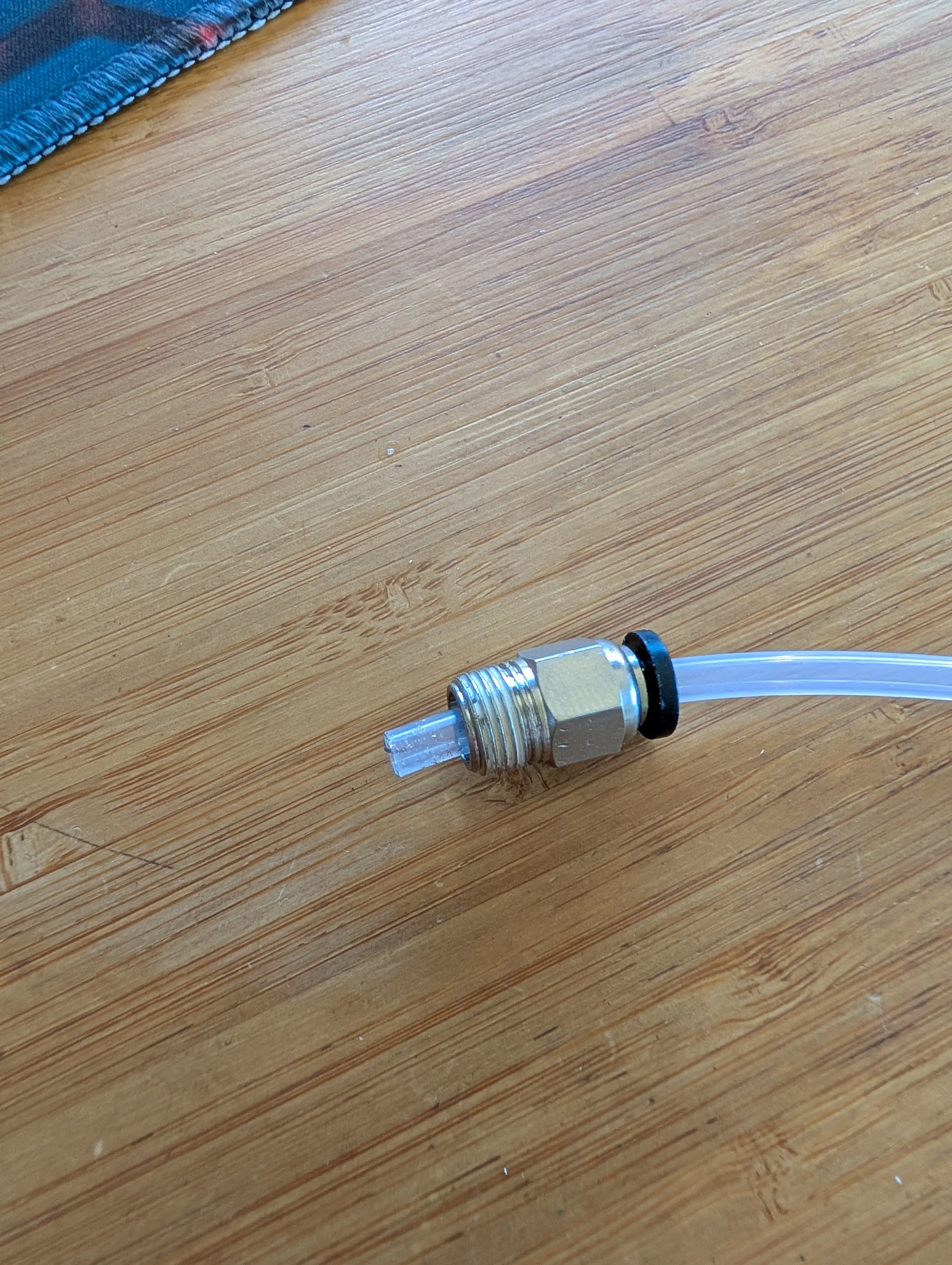
The PTFE pneumatic tube clamps are BSP 1/8 threaded.
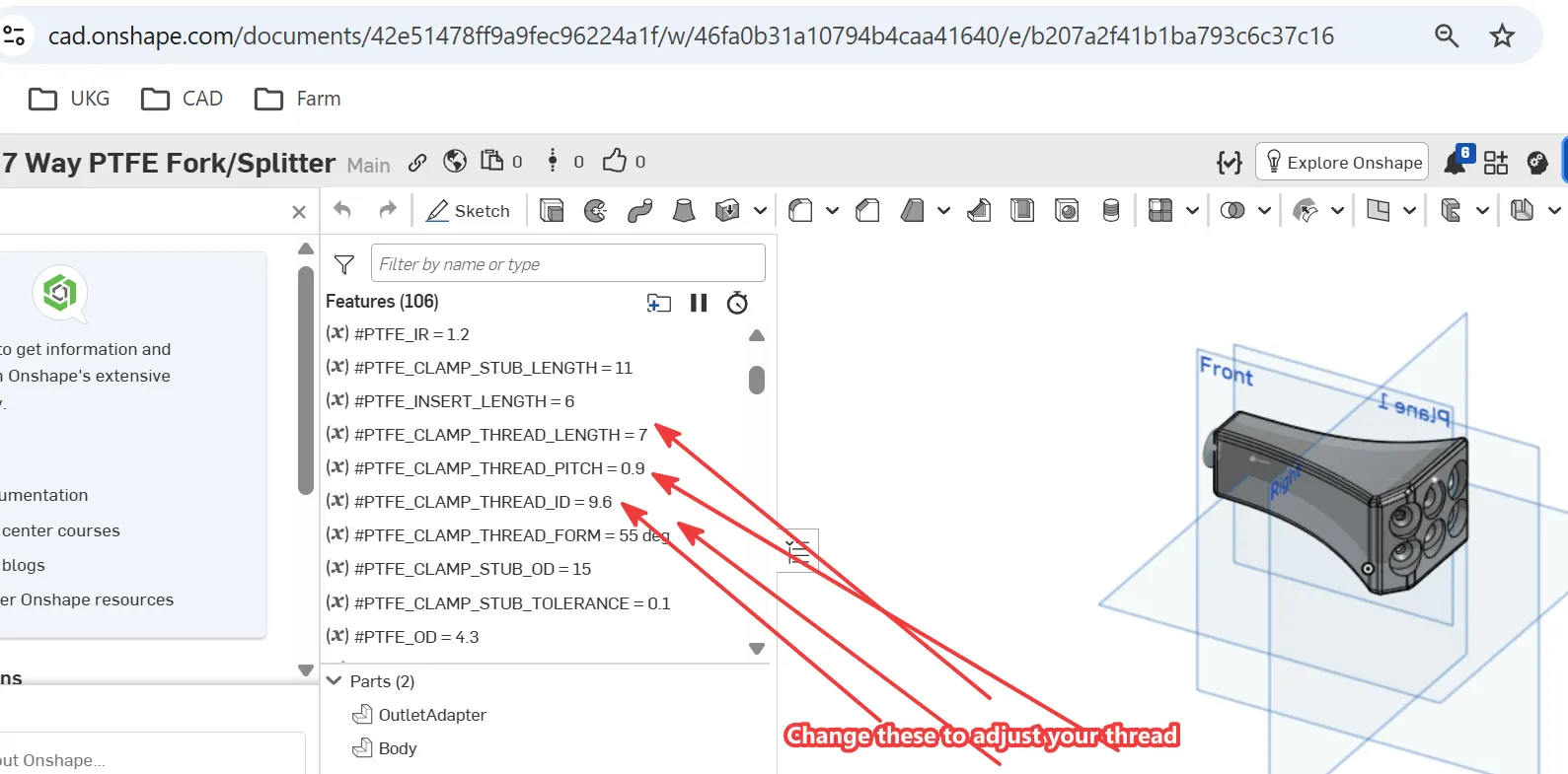
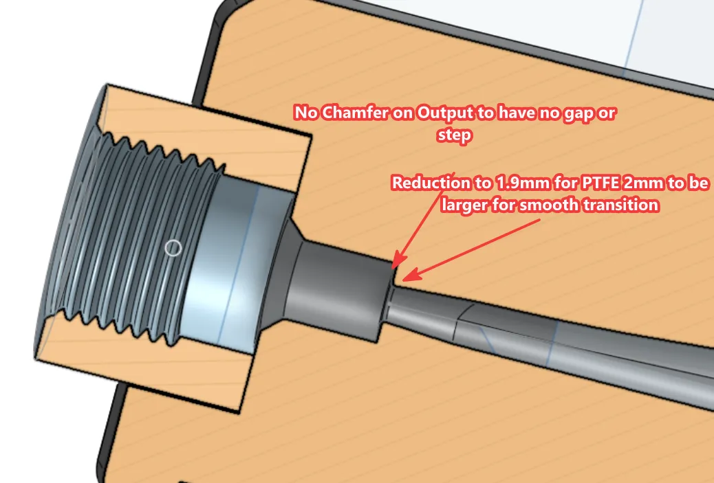
make sure the PTFE can fit through. If not widen the ID with a 4mm drill until your PTFE tube can slide through. When you install you want to push the PTFE as far through as possible, about 3mm beyond the clamp on the IN and about 6mm on the Out.
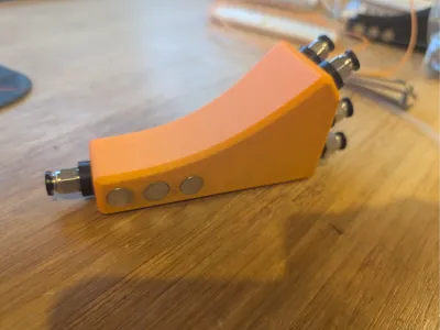
This 6 in1 or 7 way splitter is printed flat on the side to provide smooth inner tube surface finishes.
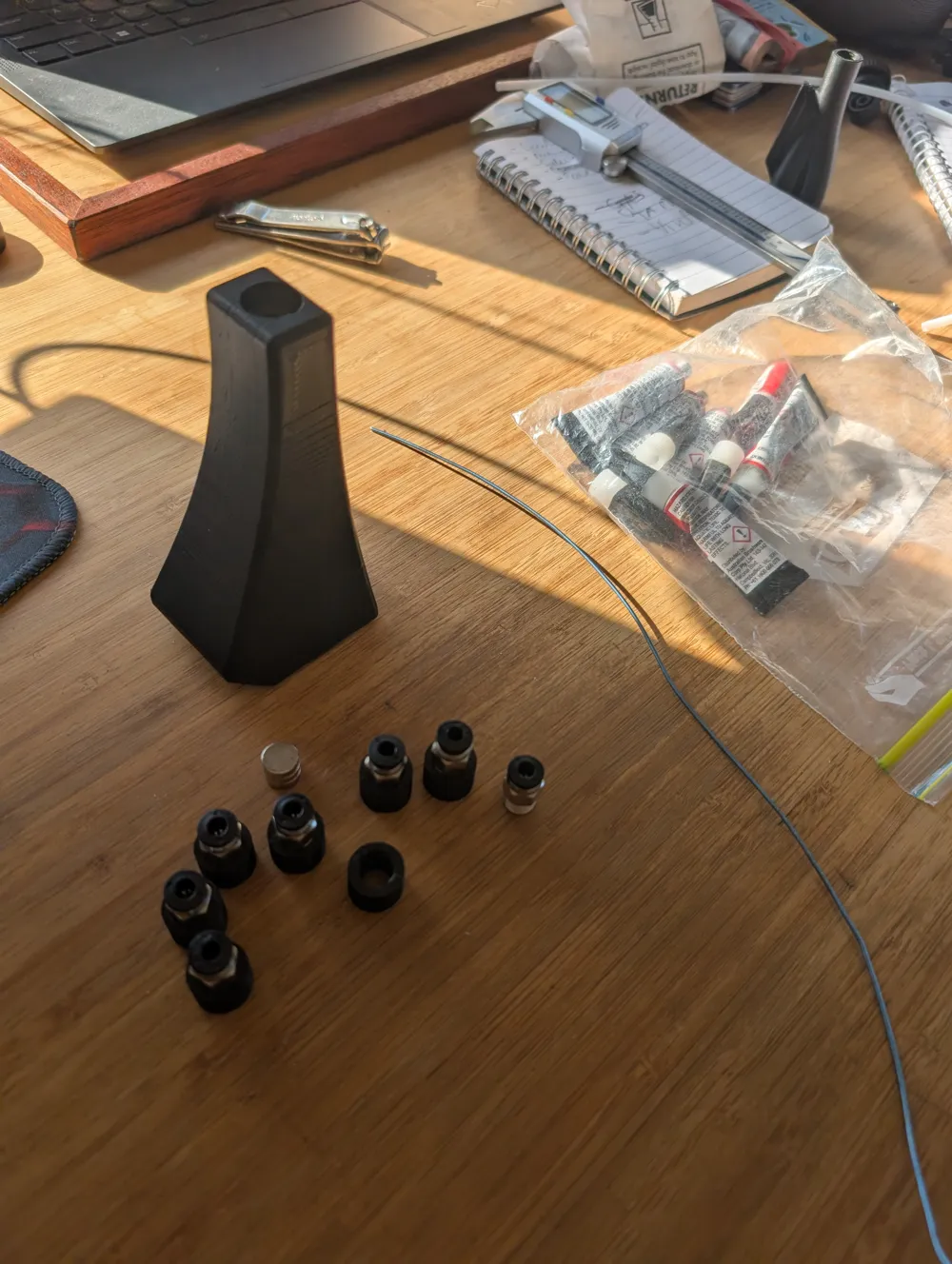
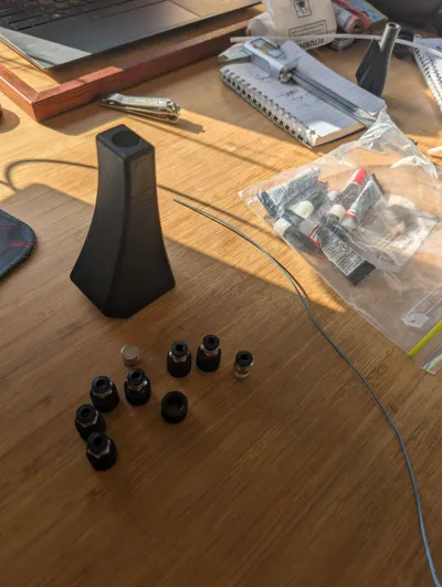
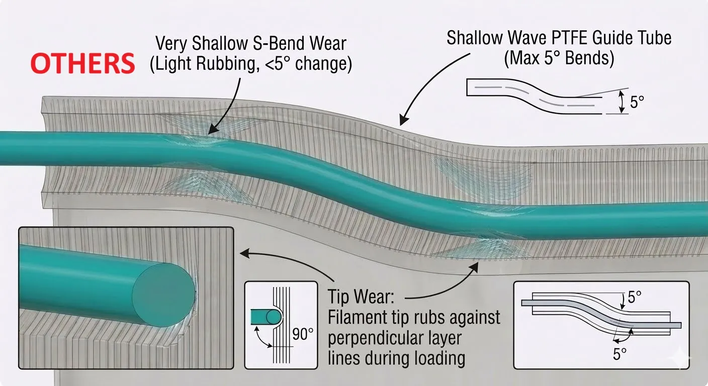
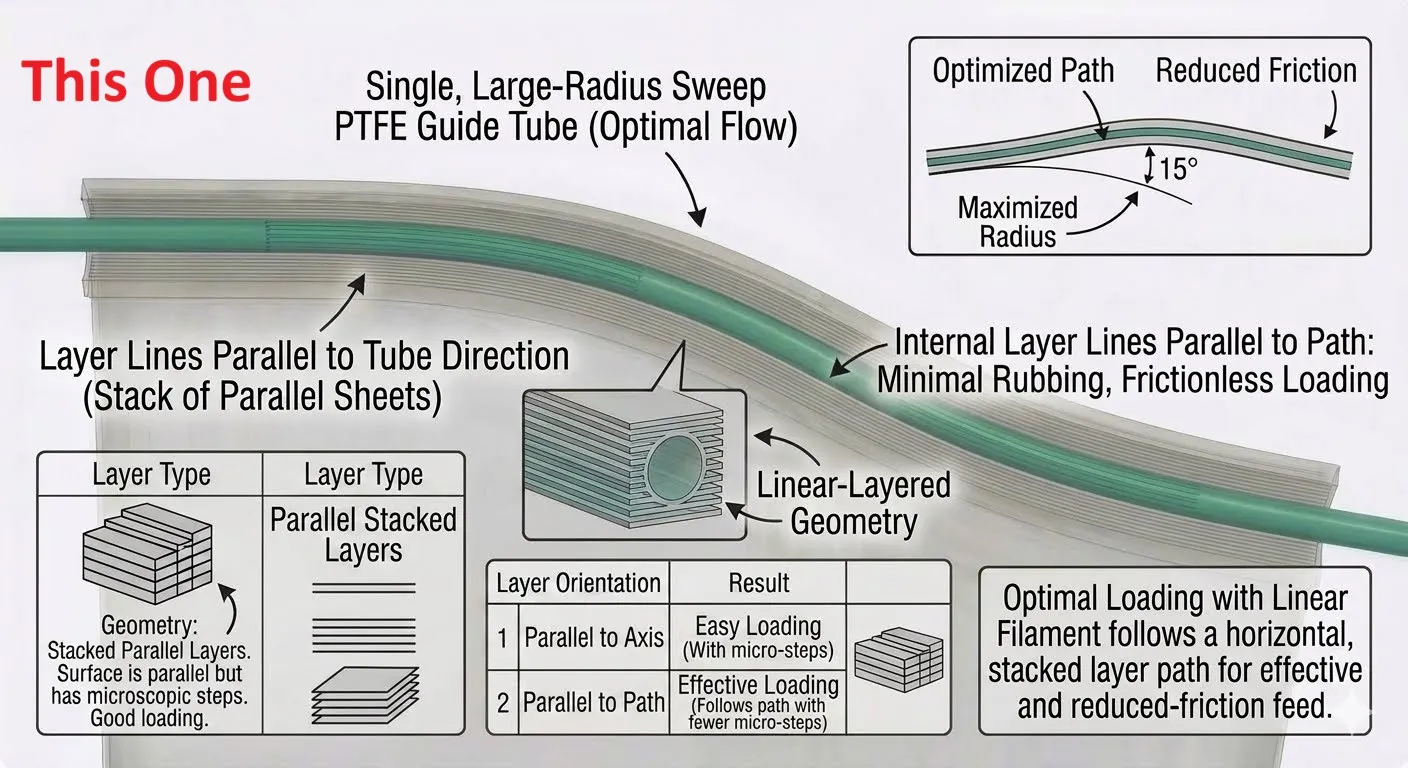
the below pictures are AI generated , I tried to explain what I am trying here. the S bend in most y splitters add extra friction, and most Splitters are printed upright to cater for the threads thus causing fiction when feeding TPU or using AMS etc. Mine is printed horizontally and the thread stubs are printed separately use superglue to fit them. That way much less friction. We could improve this by deepening the PTFE tunnel much further if needed. But it works for me as is.
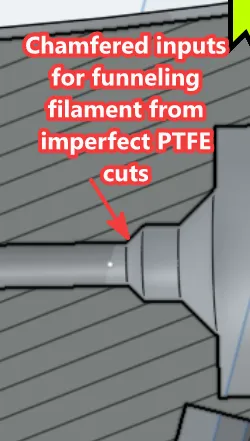
Use a fence wire 1.25mm or similar to push out any inaccuracies from printing process before feeding filament the first time. I find the straight and flat tunnels have less friction so I use those for AMS and TPU, whilst the other to print from Dryer box etc. You'll figure it out.
I tried all I could think off to minimize the risk of tip getting stuck during feeding. If you have improvement ideas let me know. Happy to play around more with it.
License



Comment & Rating (0)