Search models, users, collections, and posts
Blobifier_X Nozzle Wipe
IP Report


Print Profile(1)

0.2mm layer, 4 walls, 40% infill
Designer
1.4 h
1 plate
Open in Bambu Studio
Boost
5
3
0
0
3
0
Released
Description
Content has been automatically translated.
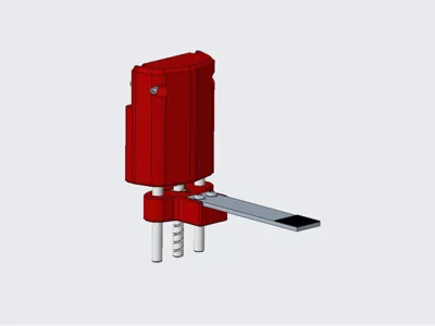
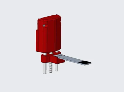
This is a variation of the Blobifier, which I have named Blobifier_X.
Actually, its physical structure is completely different from Blobifier, it only refers to its nozzle flushing idea, and at the same time makes targeted modifications in the software part. For the original Blobifier, please go here.
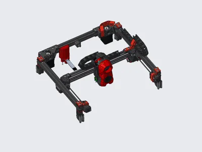
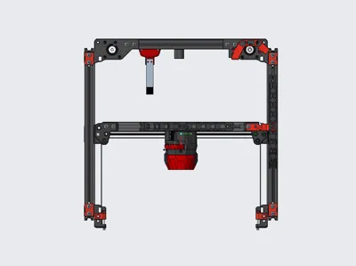
The original Blobifier is not friendly to voron2.4, it needs to raise and lower the gantry frequently, and sacrifices the effective printing area of the hotbed, while there may be a risk of the printhead hitting the model. So I designed Blobifier_X.
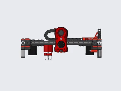
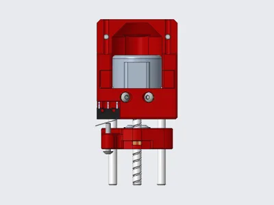
Blobifier_X is installed on the gantry, when flushing, it does not need to lower the gantry, but uses a small stepper motor to achieve the up and down movement of the tray to promote the blob formation.
Update Notes:
2024.9.1
Adjust the blob kicking logic: The last blob of the current flush is kicked out when the next flush docks, that is, the printing is resumed immediately after the flush is finished, and it no longer waits for the blobifier_x to return to its position, effectively reducing the nozzle material overflow, even without wiping the nozzle, the wiping tower/hotbed is very clean.
Bill of Materials:
- 28BYJ-48 stepper motor x1,
- TMC2209 or other driver x1,
- ∅5x50 cylindrical pin x2,
- T5 lead 4 screw rod + nut, 40 long x1,
- D2F-01L micro switch x1,
- M3x4x5 hot melt nut x8,
- M3x3 set screw x4, can also be used on BMG
- M3x10 round head hex socket screw x4,
- M3x12 round head hex socket screw x2,
- M3x16 round head hex socket screw x1,
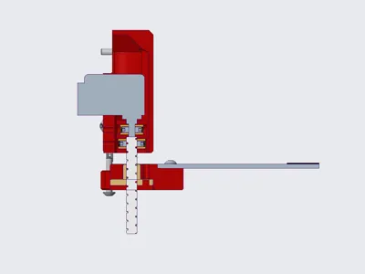
- 15x2x75 aluminum strip x1, I used CNC TAP, the aluminum strip length may not be suitable for you, please adjust it yourself, so that the front end extends 4-5mm from the nozzle, punch holes according to the following picture.
- Hotbed film 15x15mm x1, textured film, adhesive on the back, thickness about 0.4, TB many, generally black, buy the smallest size and cut it yourself.

Key Assembly Steps:
- When pressing the coupling into the hot melt nut, it is recommended to assemble it with the motor and screw rod separately before pressing it into the nut, and press the nut to the bottom.
- Cut the motor shaft surface perpendicular to its lead-out direction, and assemble it with the main body and cylindrical pin in advance.
- Assemble the screw rod, nut, coupling and slider into a whole.
- Then assemble the above two parts together, tighten the set screw at the end of the motor shaft, you may need to use pliers to rotate the screw rod so that both the relative set screws can be tightened.
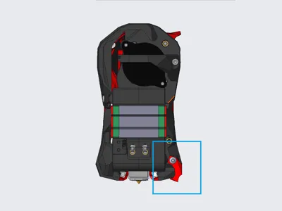
- Finally, assemble the remaining parts, don't forget the collision block on the printhead.
About motor wiring and drive instructions:
- 28BYJ-48 is a 5-wire 4-phase motor, when wiring, the red wire is not connected, the other 4 wires can be wired according to the two-phase motor wiring.
- The voltage used by 28BYJ-48 is 5V, you need to cut off the Vin (VM) pin of the drive, and lead out another wire to connect to 5V.


Debugging instructions:
- Upload Blobifier_X to the printer and include blobifier_x.cfg file in printer.cfg, modify the motor and limit pin in blobifier_x_hw.cfg.
- Important: Motor direction debugging, manually place the slider in the middle of its travel, run MANUAL_STEPPER STEPPER=blobifier_x MOVE=5 (the motor moves a short distance, such as 5), at this time the slider should move down (ie, away from the motor direction), if the movement is opposite, please adjust the motor running direction.
- Slider zero position adjustment: Adjust the collision screw (M3x16) on the slider to make the micro switch trigger, the slider and the main body leave some gap (such as 1mm, the gap size is not strictly required, to avoid the slider hitting the Blobifier_X main body when returning to zero). Install Blobifier_X on the printer, run MANUAL_STEPPER STEPPER=blobifier_x MOVE=5 to move the slider away from the micro switch, then run BLOBIFIER_HOME, the slider should move up and stop when the micro switch is triggered, this is to bring the printhead closer to the tray (be careful of collision, you can manually move the printhead), observe the distance between it and the tray. This is a repetitive process, use the MANUAL_STEPPER STEPPER=blobifier_x MOVE=5 and BLOBIFIER_X_HOME commands flexibly and adjust M3x16 to make the tray about 0.2-0.6mm below the printhead. Note: The BLOBIFIER_HOME_X command (to be precise, when the parameter STOP_ON_ENDSTOP=1 in the MANUAL_STEPPER command) takes some time (about a few seconds), the printer will not execute other commands at this time, please wait patiently.
- Finally, move the printhead to the middle of the tray, record the X and Y coordinates (the Y coordinate is generally the maximum travel of the printer Y), fill in the variable_purge_x and variable_purge_y in blobifier_x.cfg; the parameters variable_kick_ready_x and variable_kick_x are the X coordinates of the printhead preparing to kick out the blob and after kicking out the blob, you can set them yourself according to the actual situation, generally purge_x+20 and purge_x+50 respectively.
- The provided configuration files are mainly used with ERCF and HAPPY HARE, for specific parameter configuration in HAPPY HARE, please refer to HAPPY HARE and BLOBIFIER documents.
Printing suggestions:
- Increase the number of outer walls and bottom and top layers appropriately to give Blobifier_X enough strength.
- Keep the cylindrical pin mounting holes on the main body and slider in the same direction to ensure that they are as close to the same dimensional accuracy as possible.
- If the slider is too tight, you can use a drill bit to slightly enlarge the hole, but don't make it too loose, so that Blobifier_X has better rigidity, it can slide smoothly, it is recommended to apply some low-viscosity grease.
- The CAD file of the slider is provided, which can be modified according to your own situation.
- Two collision block structures are provided. The V2 version is closer to the hotbed, which avoids the problem that the blob cannot be kicked out when it is too small.
- The provided material bucket CAD file is only suitable for my own printer, it is mainly for your reference, you can modify it yourself or design it yourself.
Finally:
- There is no perfect solution for waste disposal of VORON2 structure printers at present. The current solution basically meets the requirements. As the printing progresses, the gantry gradually rises, and there is basically no risk of Blobifier_X hitting the waste.
- Thanks to the Blobifier open source project, the author's idea is really great.
Documentation (3)
Other Files (3)
blobifier_x.cfg.txt
blobifier_x_hw.cfg.txt
blobifier_x_v2.cfg.txt
License
This user content is licensed under a
Creative Commons Attribution-Noncommercial-Share Alike
Comment & Rating (0)