
Blobifier_X Nozzle Purge
Print Profile(1)
Description
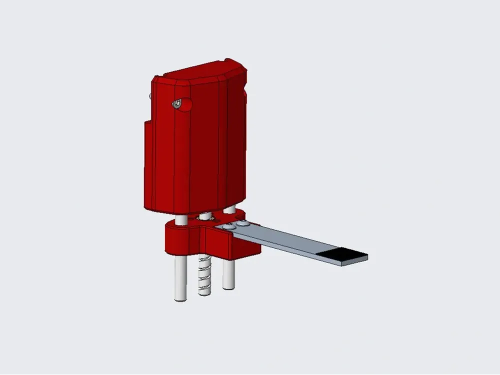
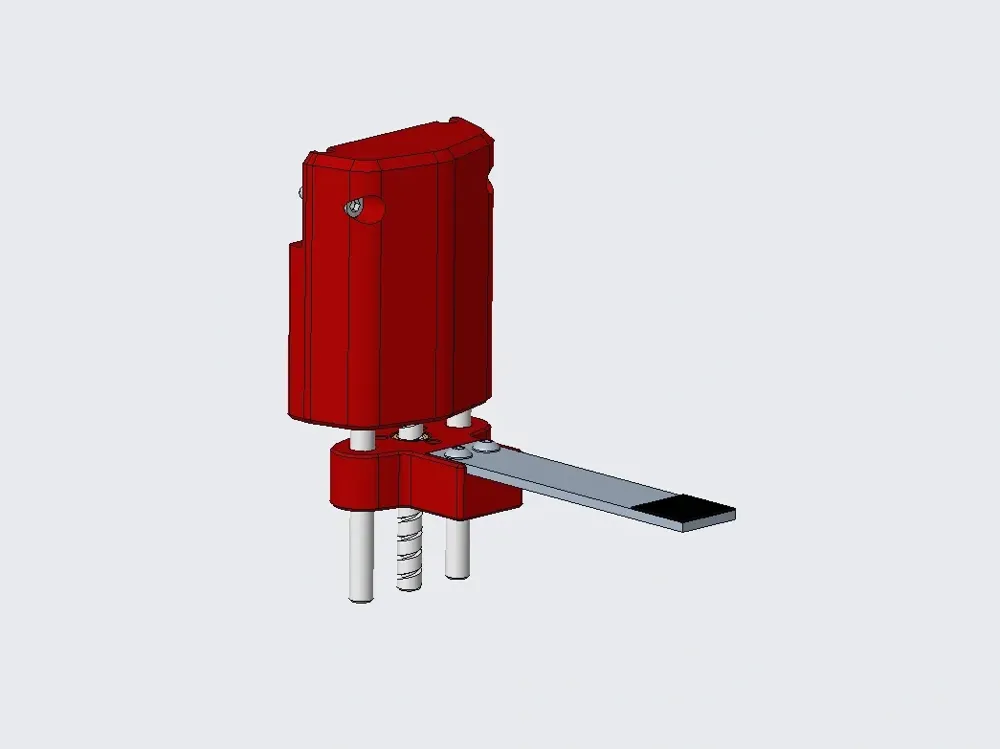
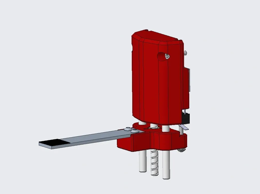
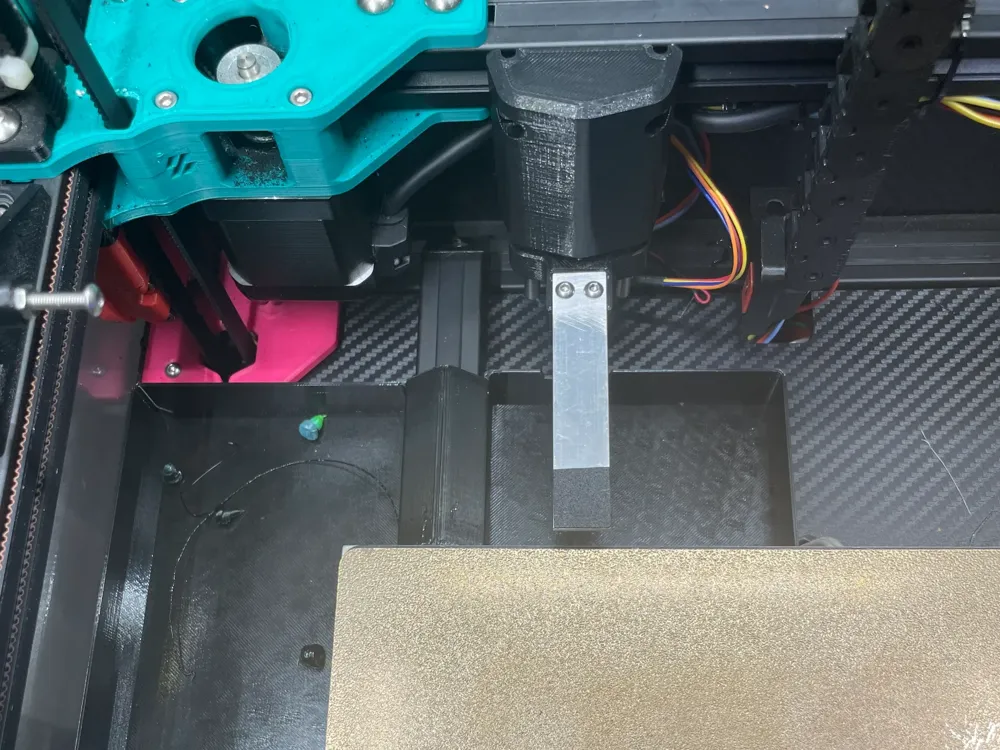
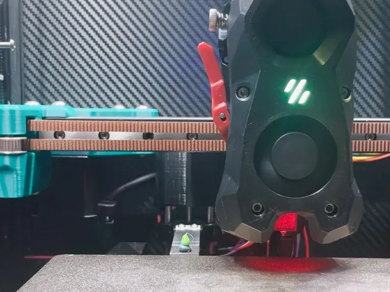
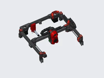
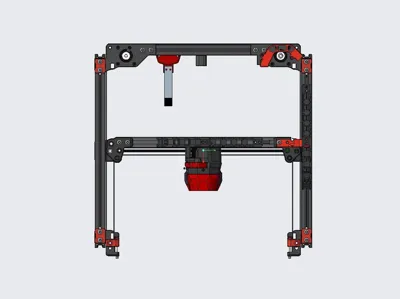
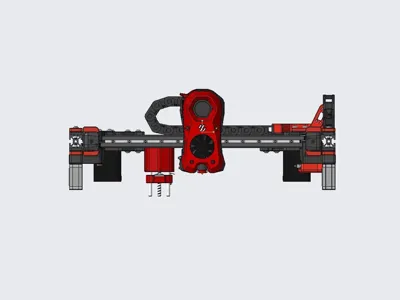
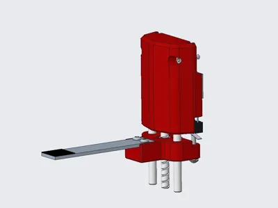
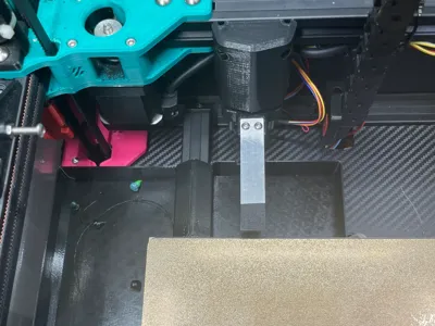
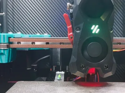
This is a variant of the Blobifier, which I've named Blobifier_X
Its physical structure is entirely different from the original Blobifier, drawing inspiration only from its nozzle-wiping mechanism, with targeted software modifications. For the original Blobifier, please visit here.
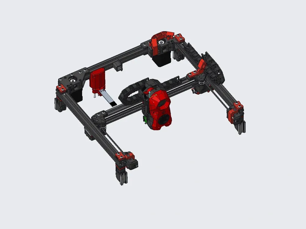
The original Blobifier is not ideal for the Voron 2.4, requiring frequent gantry movements and reducing the usable build plate area, while also risking print head collisions. Therefore, I designed Blobifier_X.
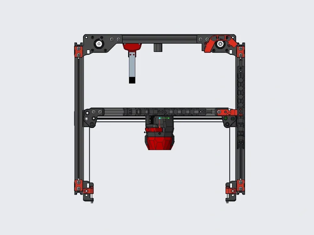
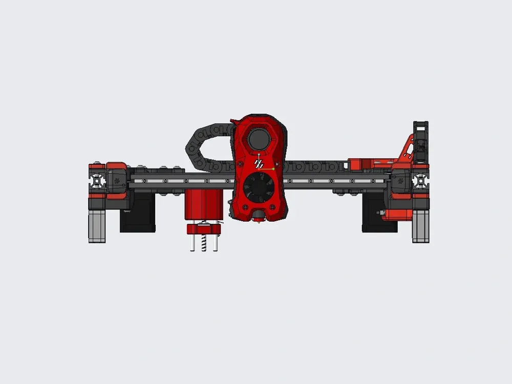
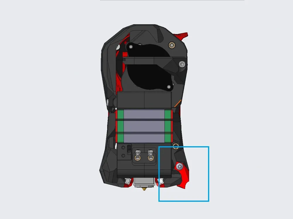
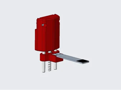
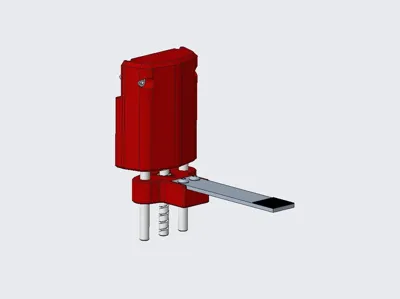
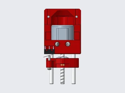
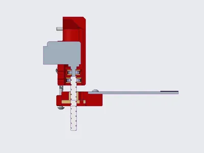
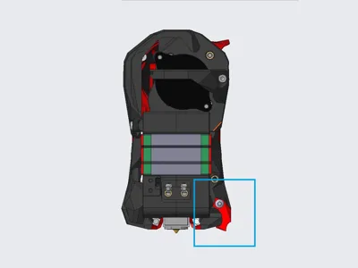
Blobifier_X mounts to the gantry; purging does not require gantry lowering. Instead, a small stepper motor raises and lowers the tray, facilitating blob formation.
Update Log:
2025.5.12
The main structure has been updated to version V2, boasting enhanced efficiency. Details are available at
https://makerworld.com.cn/zh/models/1218474-blobifier_x_v2#profileId-1296529
2025.5.4
- Updated to V2.1
- Purging method changed to a pulsating mechanism.
2025.5.3 Update
!!! Major Update to V2 !!!
The previous V2 version has been downgraded to V1.1.
- Utilizes a personally modified manual_stepper, renamed manual_stepper_fix (to differentiate it from the original instruction). The modified instruction incorporates a relative movement parameter, eliminating the need for frequent zeroing and homing during purging. The tray zero position remains fixed, preventing operational errors and facilitating debugging.
- To use manual_stepper_fix, simply import manual_stepper_fix.py into the /home/your_username/klipper/klippy/extras directory and restart the host.
- The modified instruction MANUAL_STEPPER_FIX is called using the same format and parameters as the original MANUAL_STEPPER instruction, with the addition of a RELATIVE=1 or 0 parameter. Adding RELATIVE=1 to the command call enables relative movement; RELATIVE=0 maintains the original MANUAL_STEPPER functionality.
- MANUAL_STEPPER_FIX requires Klipper version V0.13 or higher due to a bug in V0.12 that causes the command to error.
- Klipper V0.13 addresses a previous defect where, when using the STOP_ON_ENDSTOP=1 parameter, a complete command execution time was still required after the limit switch was triggered. This significantly reduces wait times, and upgrading is strongly recommended! Using the MANUAL_STEPPER_FIX command instead of MANUAL_STEPPER also effectively mitigates this extended wait time caused by the aforementioned defect, as this command only requires homing once.
- The Blobifier_X V1 code remains usable with Klipper V0.13, but based on the above description, using manual_stepper_fix + Blobifier_X V2 is still recommended.
2024.9.1
Adjusted blob ejection logic: The last blob from a purge is ejected when the next purge docks; purging completes and printing resumes immediately, eliminating the wait for blobifier_x homing. This effectively reduces nozzle filament overflow, leaving the wipe tower/bed clean even without wiping.
Bill of Materials:
- 28BYJ-48 stepper motor x1,
- TMC2209 or other driver x1,
- ∅5x50 cylindrical pin x2,
- T5 lead 4 screw rod + nut, 40mm length x1,
- D2F-01L micro switch x1,
- M3x4x5 heat-set nut x8,
- M3x3 set screw x4, also usable from BMG
- M3x10 button head socket cap screw x4,
- M3x12 button head socket cap screw x2,
- M3x16 button head socket cap screw x1,
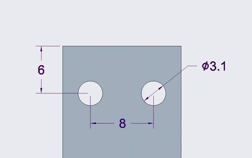
- 15x2x75 aluminum bar x1. I used CNC TAP; the bar length may not suit you. Adjust accordingly so that the front end extends 4-5mm beyond the nozzle. Drill holes according to the diagram below.
- 15x15mm build plate film x1, textured film with adhesive backing, approximately 0.4mm thickness. Many options are available on Taobao; typically black, purchase the smallest size and cut to fit.
Key Assembly Steps:
- When pressing the coupler into the heat-set nut, it is recommended to assemble it with the motor and screw rod separately before pressing into the nut, ensuring the nut is fully seated.
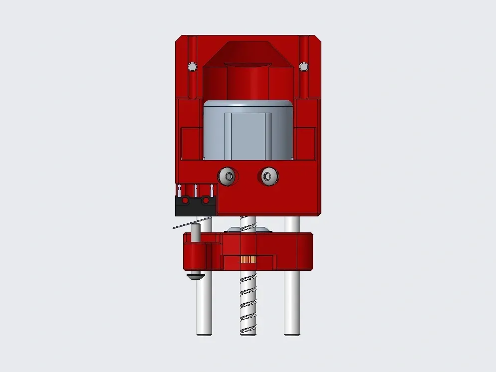
- Align the motor shaft face perpendicular to its wiring direction, pre-assembling it with the main body and cylindrical pins;
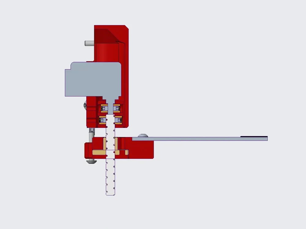
- Assemble the screw rod, nut, coupler, and slider as a single unit;
- Then assemble the aforementioned two parts together, tightening the set screw at the end of the motor shaft. You may need pliers to rotate the screw rod to allow both set screws to be tightened.
- Finally, assemble the remaining parts, ensuring the collision block on the print head is not omitted.
Motor Wiring and Driver Instructions:
- The 28BYJ-48 is a 5-wire 4-phase motor. Do not connect the red wire; connect the other four wires according to two-phase motor wiring.
- The 28BYJ-48 operates at 5V. Cut the Vin (VM) pin on the driver and connect a separate wire to 5V.
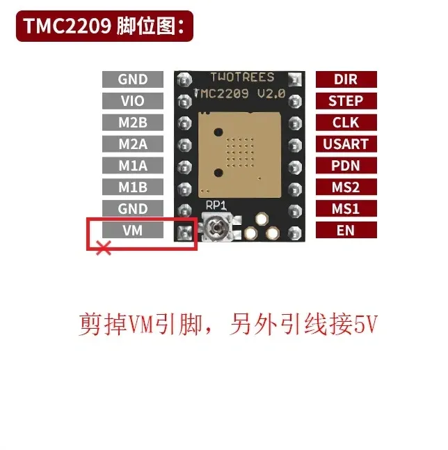
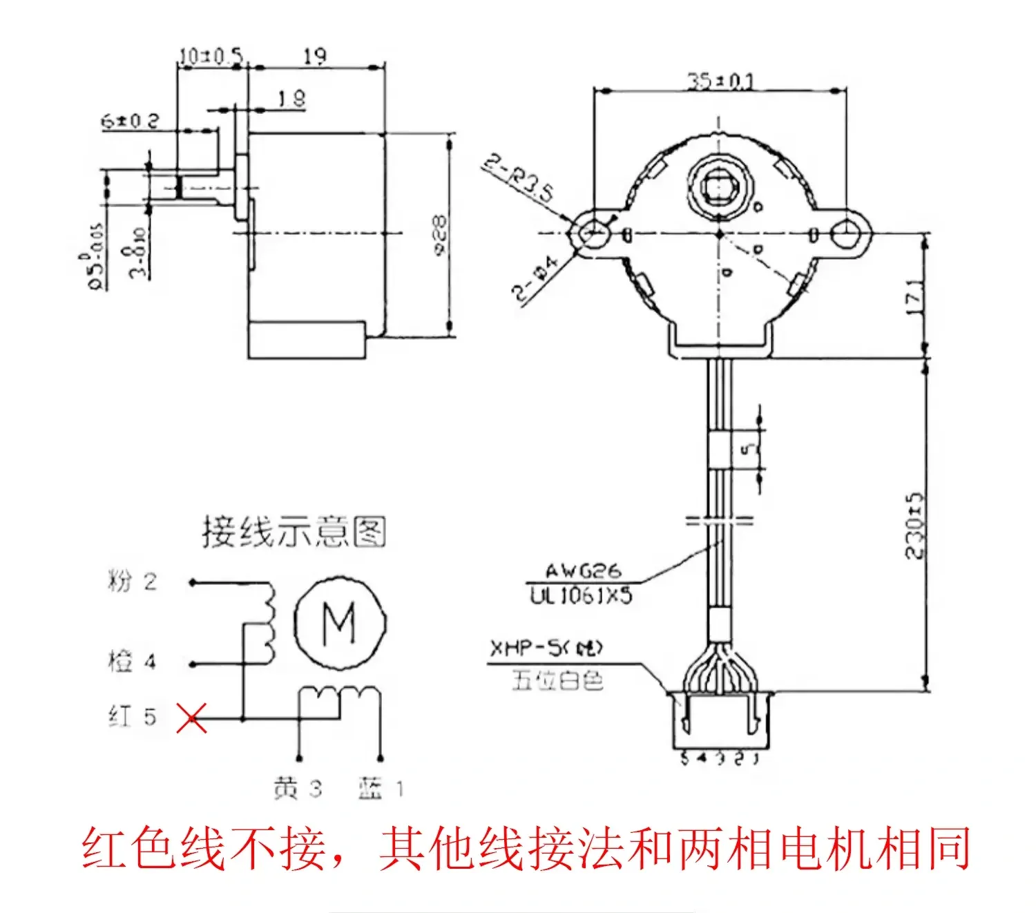
Debugging Instructions:
- Upload Blobifier_X to the printer and include the blobifier_x.cfg file in printer.cfg. Modify the motor and limit switch pins in blobifier_x_hw.cfg.
- Important: Motor direction debugging. Manually position the slider at the midpoint of its travel. Run MANUAL_STEPPER STEPPER=blobifier_x MOVE=5 (the motor moves a short distance, e.g., 5). The slider should move downwards (away from the motor). If the movement is reversed, adjust the motor rotation direction.
- Slider zero position adjustment: Adjust the micro switch collision screw (M3x16) on the slider, leaving some clearance between the slider and the main body when the micro switch is triggered (e.g., 1mm; this clearance is not strictly required, to prevent collision when the slider homes). Install Blobifier_X on the printer and run MANUAL_STEPPER STEPPER=blobifier_x MOVE=5 to move the slider away from the micro switch. Then run BLOBIFIER_HOME; the slider should move upwards and stop when the micro switch is triggered. Bring the print head closer to the tray (carefully, avoid collision; manually move the print head) and observe the distance to the tray. This is an iterative process. Use MANUAL_STEPPER STEPPER=blobifier_x MOVE=5 and BLOBIFIER_X_HOME commands flexibly while adjusting the M3x16 to position the tray approximately 0.2-0.6mm below the print head. Note: The BLOBIFIER_HOME_X command (specifically, the MANUAL_STEPPER command with STOP_ON_ENDSTOP=1) requires some time (approximately a few seconds); the printer will not execute other commands during this period. Please wait patiently.
- Finally, move the print head to the center of the tray and note the X and Y coordinates (the Y coordinate is generally the maximum Y travel of the printer). Enter these into variable_purge_x and variable_purge_y in blobifier_x.cfg; the parameters variable_kick_ready_x and variable_kick_x are the X coordinates for the print head to prepare for and then execute blob ejection, respectively. These can be adjusted based on actual conditions, generally purge_x+20 and purge_x+50, respectively.
- The provided configuration files primarily work with ERCF and HAPPY HARE. For specific parameter configurations in HAPPY HARE, please refer to the HAPPY HARE and BLOBIFIER documentation.
Printing Recommendations:
- Increase the number of outer wall and bottom/top layers to provide sufficient strength to the Blobifier_X.
- Maintain the same orientation of the cylindrical pin mounting holes on the main body and slider to ensure consistent dimensional accuracy.
- If the slider is too tight, use a drill bit to slightly enlarge the holes, but avoid making them too loose, preserving the Blobifier_X's rigidity. Smooth sliding is desired; apply a low-viscosity lubricant.
- The slider CAD file is provided for customization.
- Two collision block designs are available; the V2 version is closer to the bed, preventing ejection issues with smaller blobs.
- The provided filament container CAD file is specific to my printer and serves as a reference only. Modify or design your own as needed.
In Conclusion:
- Currently, there is no perfect solution for waste disposal on VORON 2 structure printers. This solution largely suffices. As printing progresses, the gantry gradually rises, minimizing the risk of Blobifier_X colliding with waste.
- Thank you to the Blobifier open-source project; the author's creativity is truly remarkable.
Documentation (5)
License



Comment & Rating (3)