
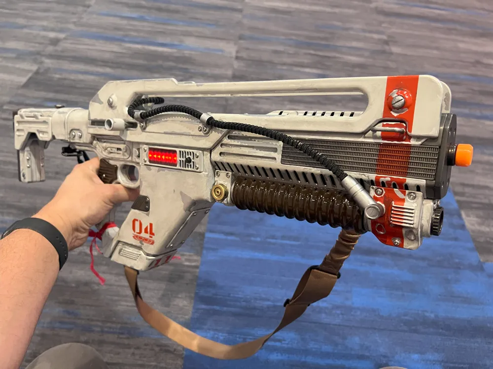
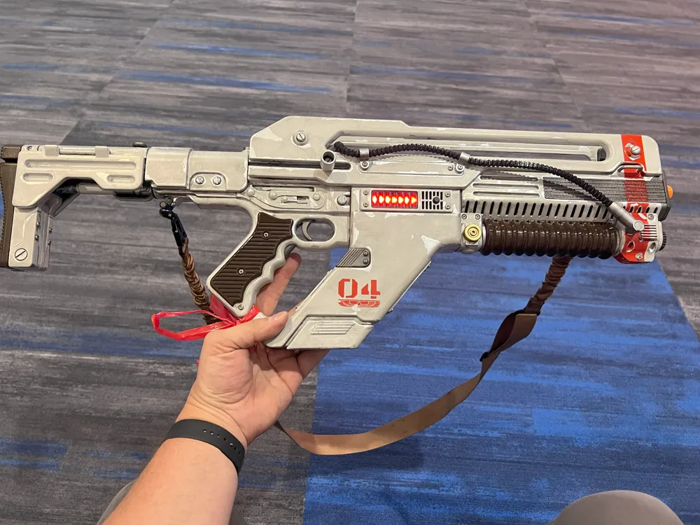
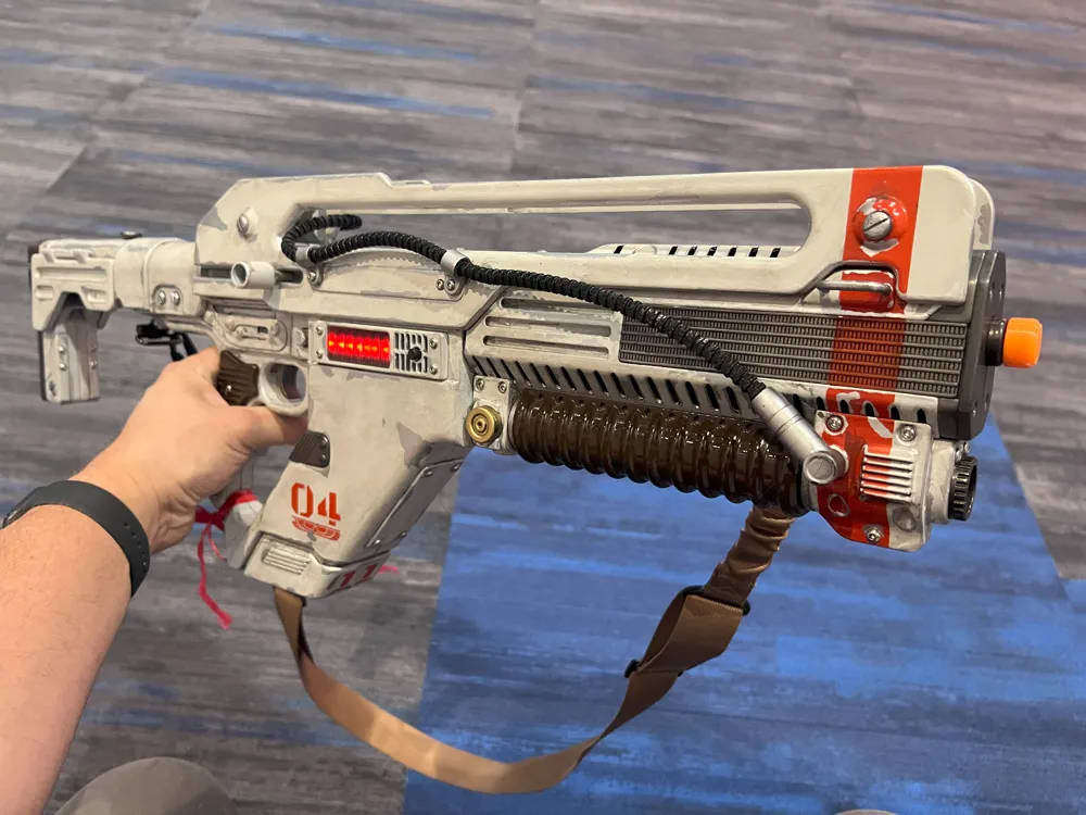
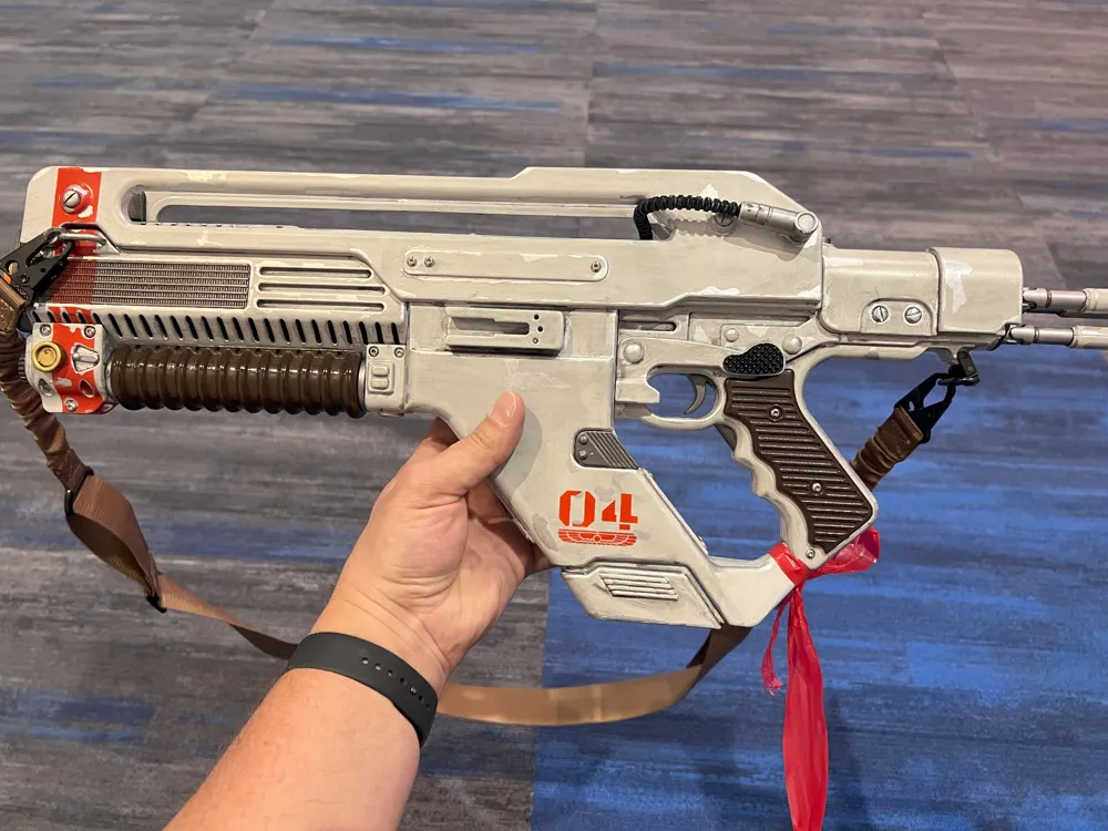
F44AA Pulse Rifle from Alien: Romulus


Print Profile(1)

Bill of Materials
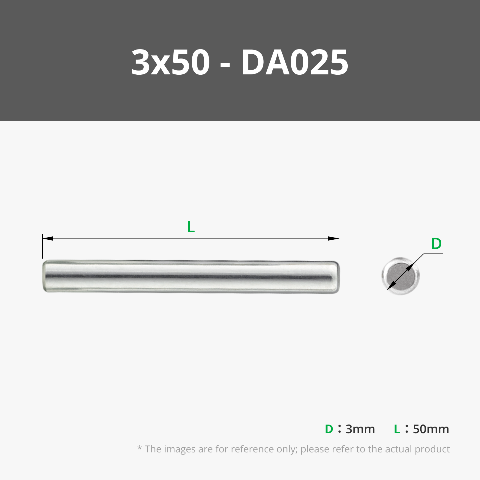
- M3x14mm Button Head Screws x 1: 55
- M3x8mm Button Head Screws x 1: 4
- 6x30mm springs x 1: 2
- 3x20mm rod for trigger x 1: 1
- 6x150mm dowel rods for stronger stock (1/4" is very close to this size) x 1: 3
- Super Glue (CA) x 1: 1
- 3x60mm Rod for stock wings x 1: 2
- 7mm locking on/off switch (For electronics panel) x 1: 1
- Gun Sling Swivel for Rifles (For rear attachment point) x 1: 1
Description
Update: Added a simple wall mount. Supports at back of the barrel grip and under the trigger guard. I designed it to use as little material as possible while still looking somewhat in universe. Prop will rest against wall be warned if that is a problem.
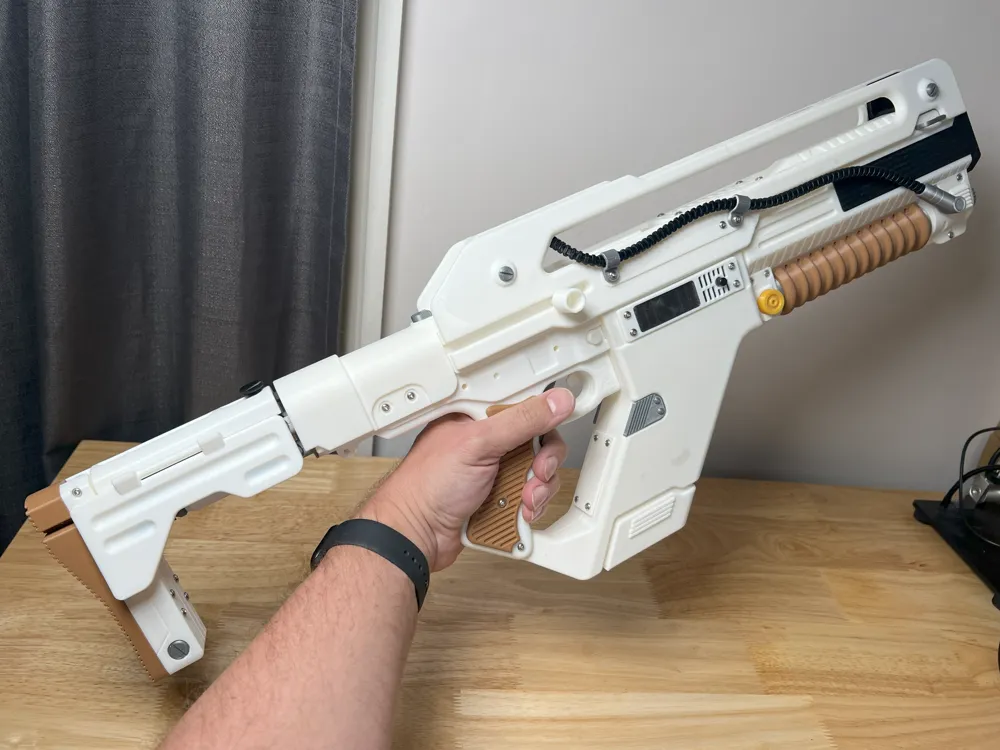
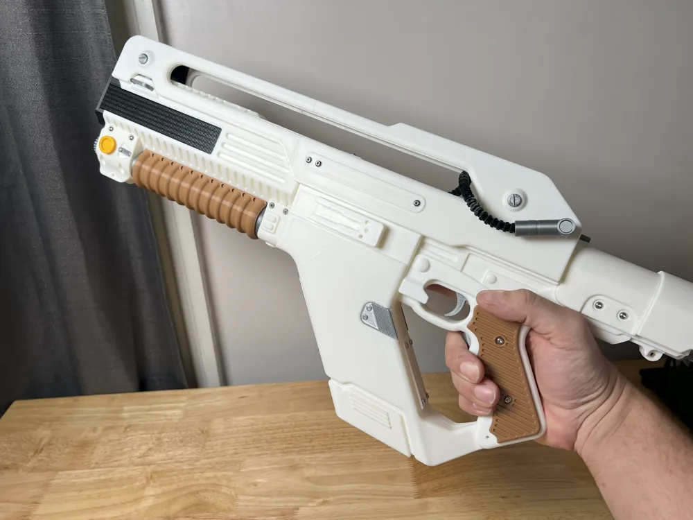
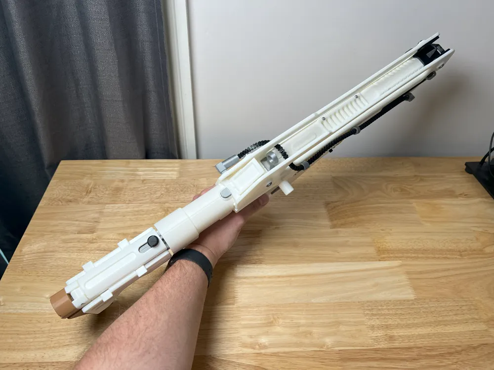
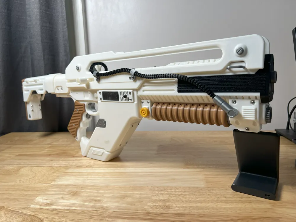
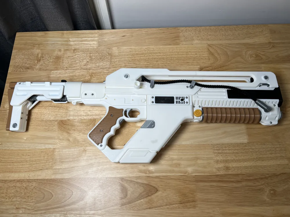
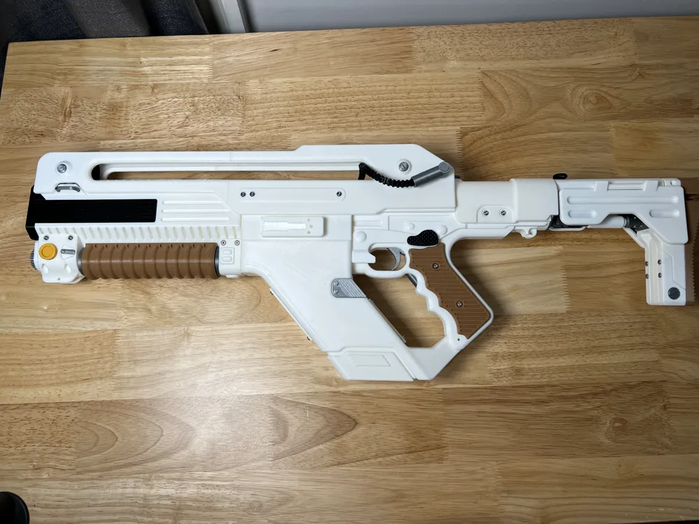
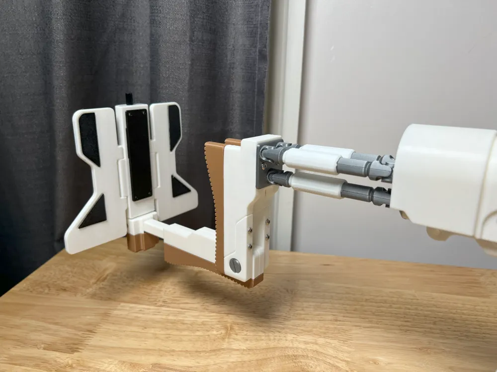
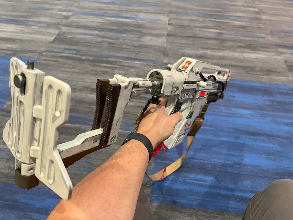
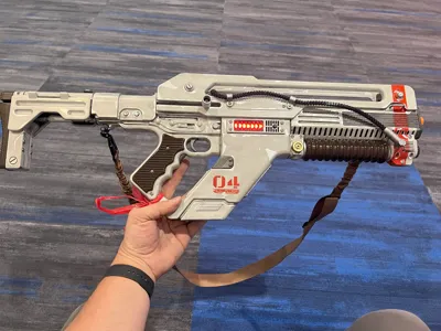
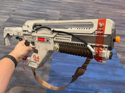
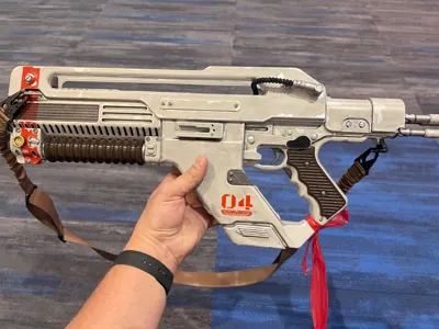
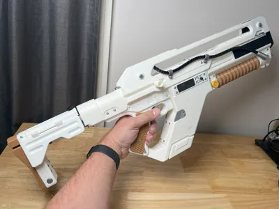
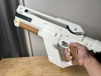
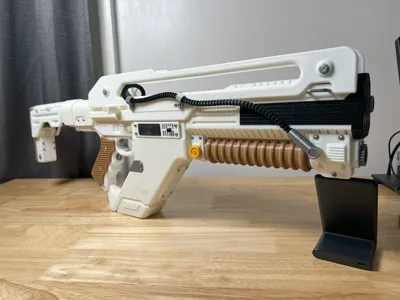
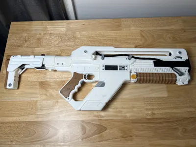
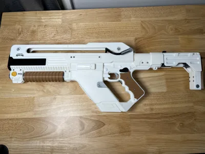
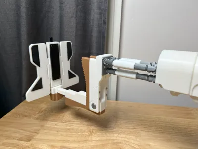
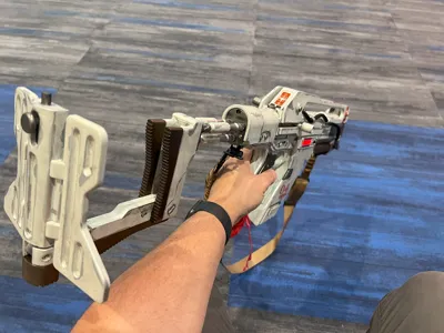
My version of the F44AA Pulse Rifle from the movie Alien: Romulus. I have tried to keep it as accurate to the film prop as possible. I have used film screenshots, pictures of stunt props, and images from the official replica to come up what I think looks pretty close to the original. I have included some extras such as: movable stock with fold out wings, working trigger, and a foldable screen.
Fair warning, this prop has a lot of pieces for assembly. This was done to maximize the printability and accuracy of the prop. I have been able to hide almost all the seam lines into logical divisions. The top handles being the only sacrifice since they are almost 400mm long and wouldn't fit on the bed in one piece.
I have put together a video of how the major parts fit together. Glue is suggested on the front receiver halves and the front barrel surround for better strength. I have included alignment aids that I have marked as “joiners”. They are critical for assembly and make for a much stronger overall model. The screws have been not been animated but are installed in the obvious places and don't require any special attention beyond alignment. The screws on the bottom of the grip need to be shorter due to the model being thinner in that area. Use a low power setting on a drill/impact driver to save time.
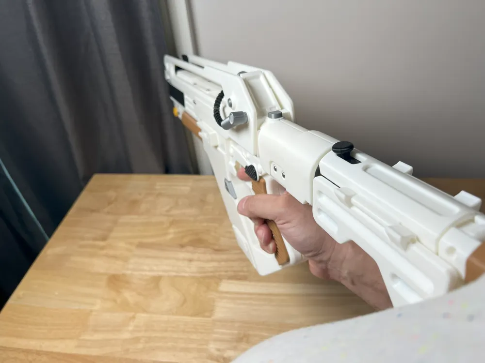
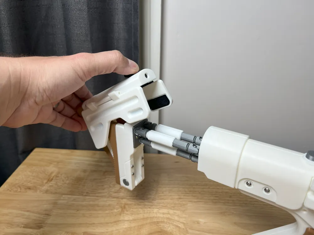
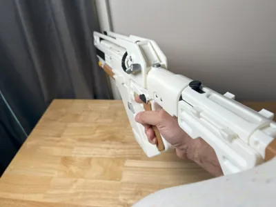
The folding stock has a rotation limiter. Please notice its correct raised position here:
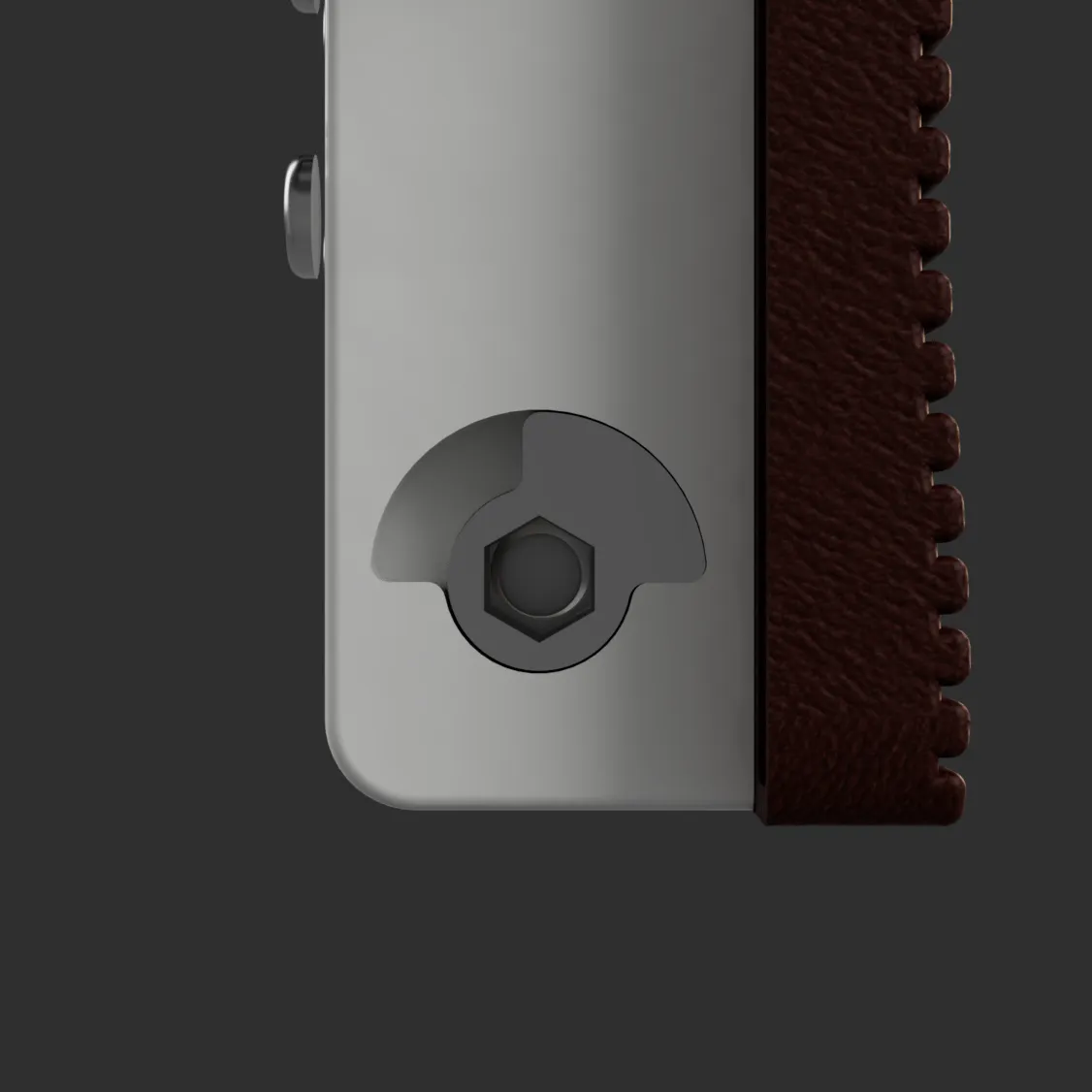
It will be locked into place with a double ended bolt that will go through the endcap and into the limiter. The hole will be very tight to maintain the proper degree of rotation. Cleanup may be neccesary with a file or sandpaper depending on the quality of your print. Screw on the caps on both ends of the bolt to keep it in place.
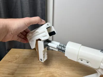
The “arms” that attach the stock come as 2 different options. I have included a hollow version that can have a 6x150mm rod inserted through it and attached to both the rear grip and endcap. This is much stronger option. There is a 3d printable option with the rod being printed with the rest of the body. This will have flex and be potentially more fragile. There is a cover either option that goes over the arm with 2 halves.
The cable is intended to printed in a flexible filament like tpu. I used superglue (CA) to join the halves. The glue does not hold for peeling apart at the ends but since the ends will be in the connectors, I don't believe that should be an issue. The cable is intentionally too long. It will need cut down to size based on preference. I suggest cutting the inner curled section since it does not bend as well as the outer portions.
The electronics panel needs a 7mm push button switch. There are slots for 7 - 3mm leds and plenty of room for a battery if you want to light it up.
I have included a multi color 3mf in the source files. It is untested and I do not suggest its use due to material waste. Only the magazine and receiver parts are worthwhile in my opinion. Use at your own risk. Painting is the better option.
I have included the vector (SVG) file for the markings in a zip file. I have also included a basic screen image that can be printed on a standard 4x6 photo paper and cutout. There are multiple sizes due to variations in the printers.
Interactive 3D Model
Assembly Video
Overview of Finished Prop
License



Comment & Rating (105)