


Print Profile(1)

Bill of Materials
- Lager 12x28x8 x 2: Wetterfest
- Schraube M5x20 x 3: A4
- Mutter M5 x 4: A4
- Schraube M5x50 x 1: A4
Description
3.6.2025 NEW optimized version! (now also with mounting foot and bearing shaft)
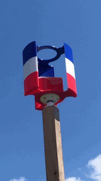
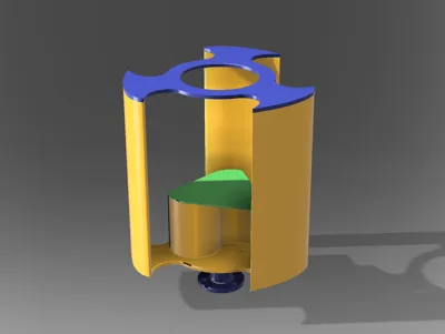
Currently, I am interested in the function of vertical wind turbines. For this, I first built a model of a wind rotor to test its function and airfoil profiles. The windmill is designed according to the Darrieus concept. To achieve better starting, a Savonius blade is additionally integrated
The wind turbine needs some wind, it starts operating from approximately 3-4 Beaufort
I have also experimented quite a bit to attach a generator
Result so far: At this size, operating even a small generator is not practical
The required starting torque is too high and the rotor only starts operating in very strong winds
If one wants to attach a generator, the system would need to be significantly increased in diameter and height
But as a demonstration model for a vertical system or as a wind chime, it works very well ;-)
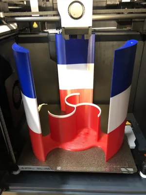
The system is designed in such a size that it can be printed on a 256x256mm plate
The upper and inner covers are glued on, for this, there is a component centering feature for each
For assembly, the following is additionally required
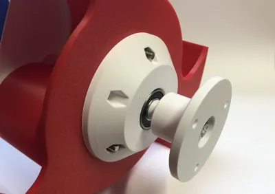
Two (encapsulated, weather-resistant) bearings ID:12mm OD:28mm W:8mm
For screwing the bearing block: 3 screws M5x20 or M5x25 with nuts
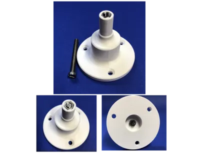
For the bearing shaft, one screw M5x50 and one nut M5
To make the bearing shaft more stable and less prone to breaking, an M5x50mm screw is inserted through the foot and fastened with an M5 nut at the tip
(Note: for a more stable bearing, a 12mm diameter metal shaft can also be used, which is mounted directly to the mast)
The two bearings are to be pressed flush into the bearing block from top and bottom
Assembly sequence
- first screw the foot to the mast
- then press the bearing block onto the shaft
- and then screw the wind blade to the bearing block
The shaft is pressed into the bearings, if the fit is too tight, sand the shaft a bit with sandpaper
PS: Unlike shown in the pictures, the bearing block is now fastened with only three screws. (this is sufficient)
Have fun trying it out
Boost Me (for free)
If you like the design, I appreciate a 'boost me'
Membership
By signing up as a member, you receive permission to use physical prints of my models for commercial purposes.
 © Staprin3D
License
You shall not share, sub-license, sell, rent, host, transfer, or distribute in any way the digital or 3D printed versions of this object, nor any other derivative work of this object in its digital or physical format (including - but not limited to - remixes of this object, and hosting on other digital platforms). The objects may not be used without permission in any way whatsoever in which you charge money, or collect fees.
Comment & Rating (94)