J-58 Engine of the SR-71 Aircraft


Print Profile(1)

Bill of Materials
- Super Glue x 1: Super Thin
- 608 2RS Ball Bearings x 2:
- M3 x 8 hex socket head cap screws x 8: black-oxide
- M3 Hex Nuts x 8: black-oxide
- M2 x 6 hex socket head cap screws x 7: black-oxide
- M2 Hex Nuts x 1: black-oxide
- M5 Hex Nuts x 1: Stainless Steel
- M5 x (12 or 15) button head screw x 1: Stainless Steel (Depends on my adjustments to the model)
- M5 Washers x 1: Stainless Steel
Description
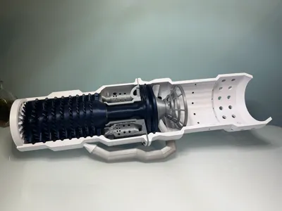
The Pratt and Whitney J-58 engine is the engine of the SR-71 Blackbird, a strategic reconnaissance aircraft used by the United States Military. This is known amongst engineers as one of the greatest engine planes ever made due to its unique engine.
Usually, there are three types of engines: turbojet, ramjet, and scramjet. Most planes use a turbojet engine as ramjets, and scramjets rely on the forward motion of the plane to generate thrust and, therefore, need to be moving at least Mach 2 (for ramjet) or Mach 5 (for scramjet). The SR-71's engine is unique in that it combines the concepts of the turbojet and ramjet, making a turbo-ramjet engine. The plane used the turbojet to fly off the ground and then switched to ramjet mode once it reached Mach 2. The plane reached a max speed of Mach 3.2, 2455 mph or 3951 kph, essentially flying a mile in under a second.
There are many videos explaining the J-58 engine, so I'll put links below.
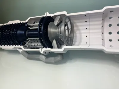
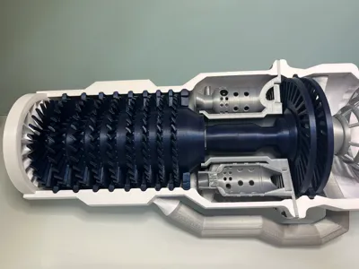
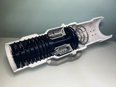
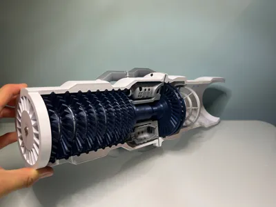
There are five main sections to my model, which contain the housing shell of the engine, the compressor, the combustion chamber, the afterburner, and the iconic bypass tubes. Due to running out of time for the engine competition, I could not design the afterburner's variable propelling nozzle (the flap-thingy at the end of the engine). At some point, I will add this and other parts of the engine, but I need more time. I may remix Linus3d's variable propelling nozzle as it looks quite good, or I may design my own, but this feature will be added. After I add this feature, I intend to add LED lights, design the inlet spike, and maybe the SR-71's start cart that was used to start the engine on the ground.
Bill of Materials:
Superglue (Thin works best)
8x M3 x 8 hex socket head cap screws
8x M3 hex nuts
7x M2 x 6 hex socket head cap screws
7x hex nuts
2x 608-2RS ball bearings
2x M5 x 12 button head screw
2x M5 hex nuts
Supply Links:
Printing Instructions:
Unfortunately, I don't own a Bambu Labs printer, I have a Creality printer. That being said, the printing tolerances are undoubtedly going to be better and different on any Bambu Lab printer. I tried to adjust the tolerances as best for everyone, but please contact me if there is a problem with the tolerances on a Bambu Lab printer.
The model contains very few supports. I set the print profile to the standard 15%, but I used 5 to 10% infill on some prints to save filament. Please feel free to adjust the infill, but do so at your own risk. The only tricky section to print is the front housing unit of the engine; the very top has a slight overhang that may turn out rough. I turned off supports for this, but you may want to turn them on as the tolerances of this section are important. However, a Bambu lab printer might be able to accomplish the task without support, I am unsure. Please feel free to ask questions. Use supports for the flame ring, torch igniters, and the combustion canister(the very small spot where one of the cans is cut in half, you'll see it).
And for the love of everything, please print the bypass tubes. It doesn't seem like much, but the tubes are the key feature of the engine.
Assembly:


Comment & Rating (23)