
A1 AMS lite Modification Enclosed Dry Box Sealing
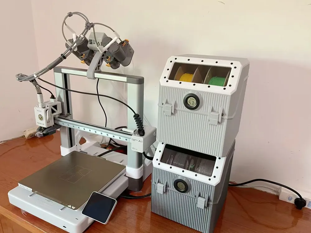
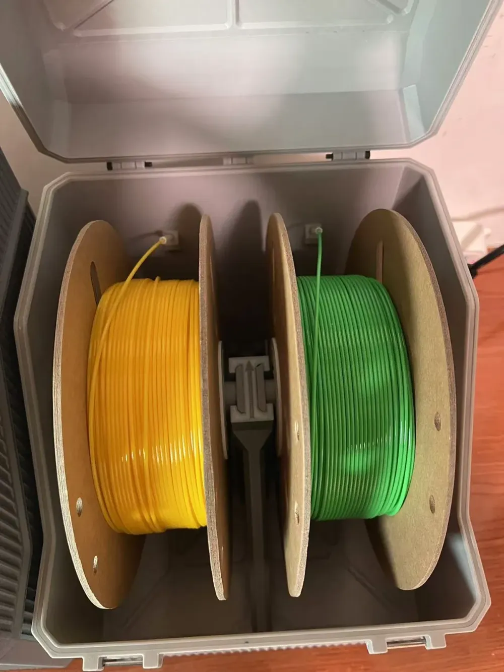

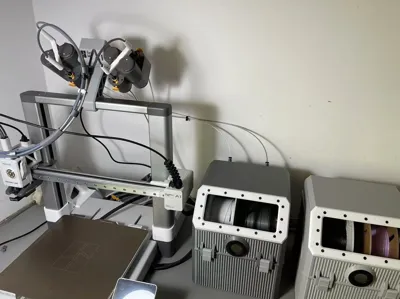
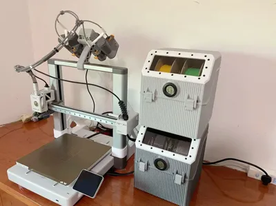
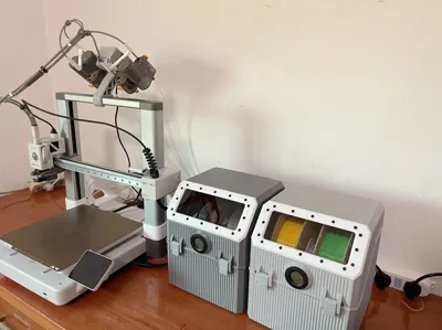
Print Profile(1)
Bill of Materials






- 170x70x2mm透明塑料板 x 2:
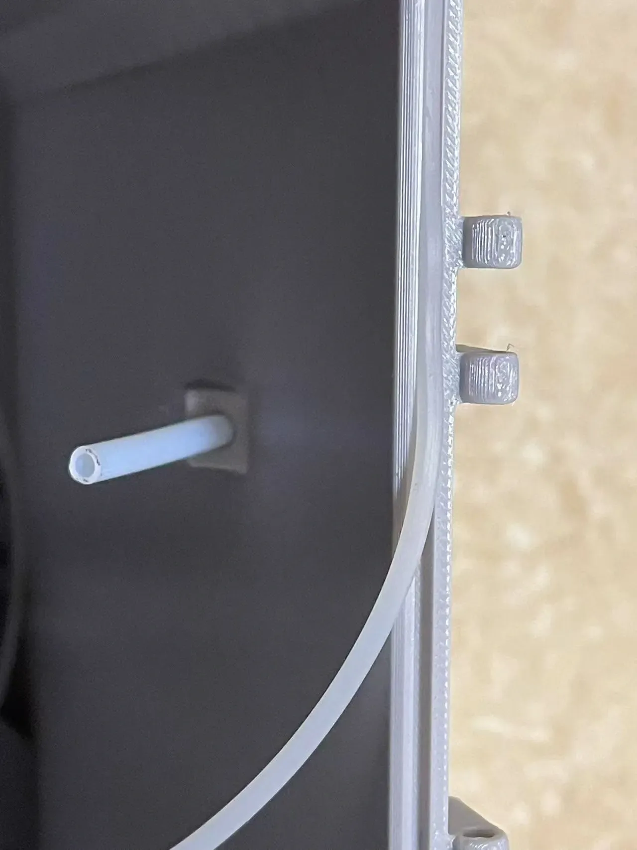
- 硅胶密封条2X2MM x 1: 2米
Description
Boost Me (for free)
If you find my design helpful, your support would be greatly appreciated Thank you!
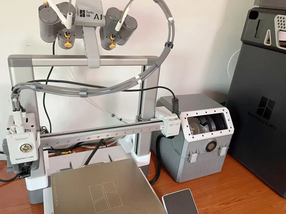
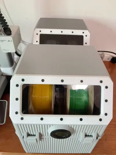
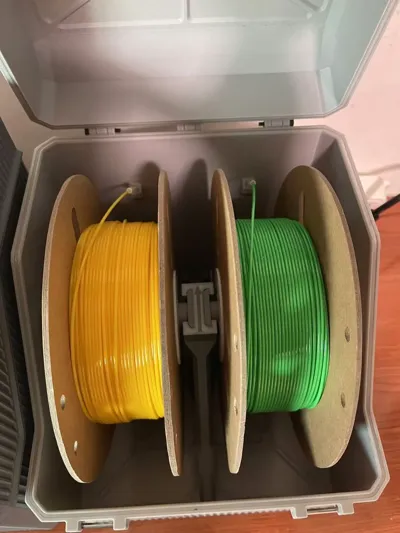
Design Rationale: Unlike the fully enclosed AMS, the AMS lite lacks a sealed compartment Due to the high humidity in my region, filaments exposed to the air readily absorb moisture, impacting print quality This design, therefore, provides a modified enclosed compartment for the AMS lite, accommodating two filament spools in a single unit for convenient and adaptable placement
Important Considerations!!!! Due to the model's substantial print area, thoroughly clean the PEI plate before printing If necessary, apply adhesive to enhance adhesion and prevent warping
Update: An additional cover has been added to the filament outlet In the second print configuration, if you have already printed the cover without holes, you can simply drill holes into the existing cover Note that when using the top outlet, the filament holder must be inverted
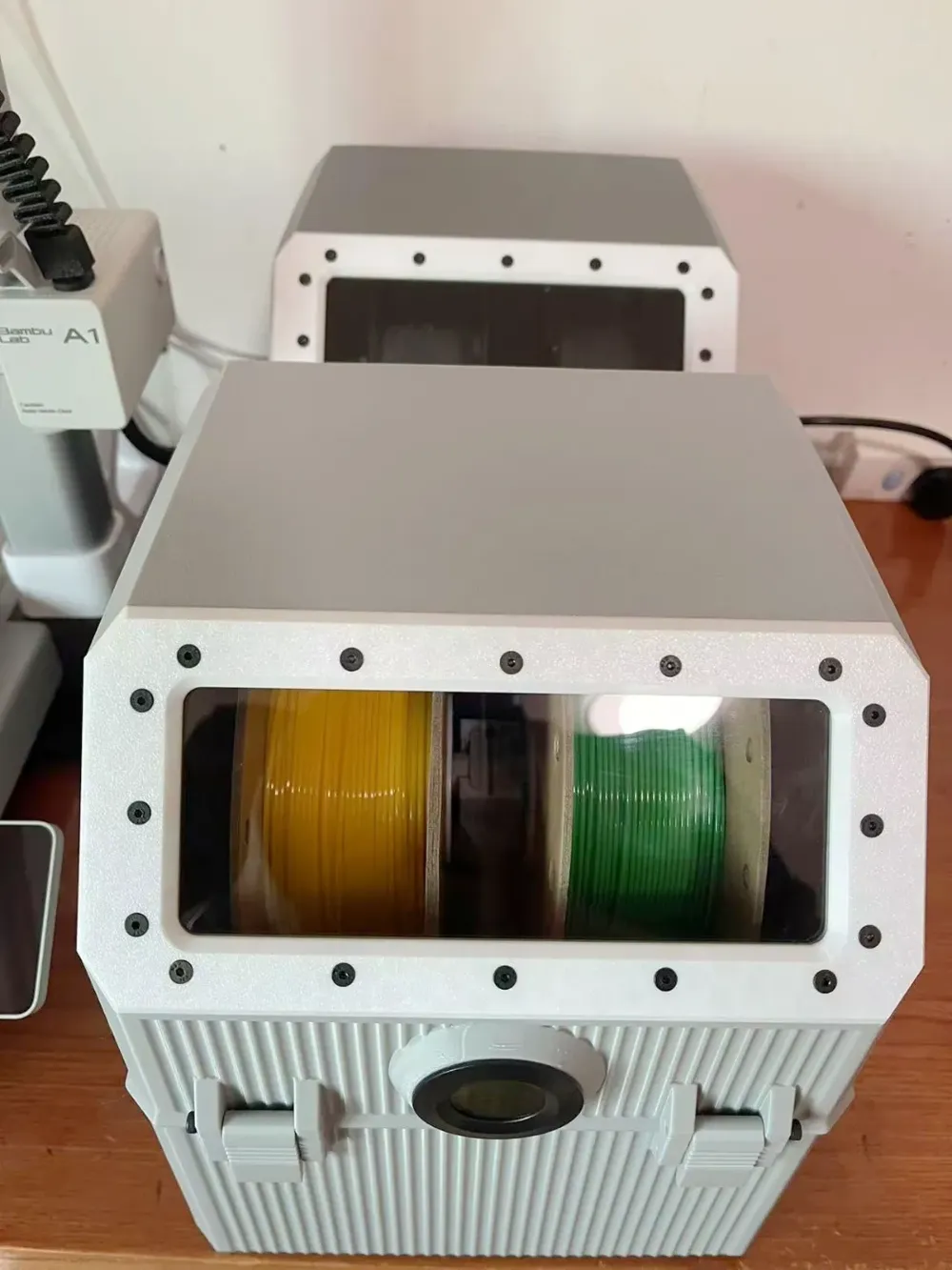
Regarding humidity control: With the addition of desiccant (consider using a slightly larger amount for prolonged effectiveness), humidity levels below 15% can be maintained for at least two weeks Frequent opening of the enclosure will reduce this duration Additionally, the desiccant container's seal significantly impacts the duration of low-humidity maintenance Avoid stretching the seal during installation, as stretching creates gaps
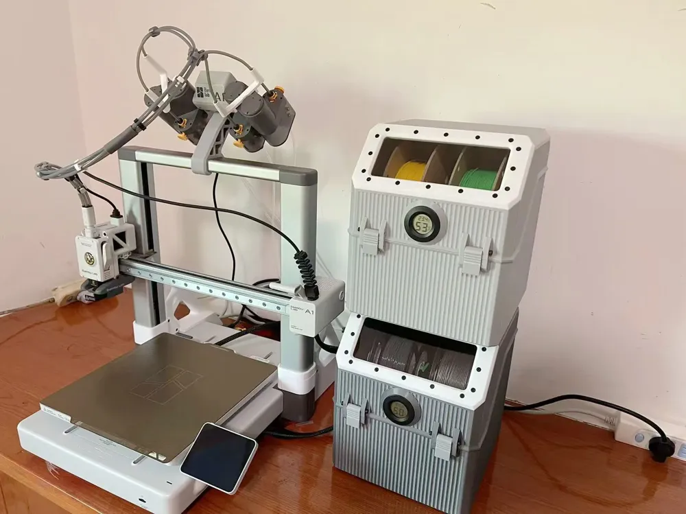
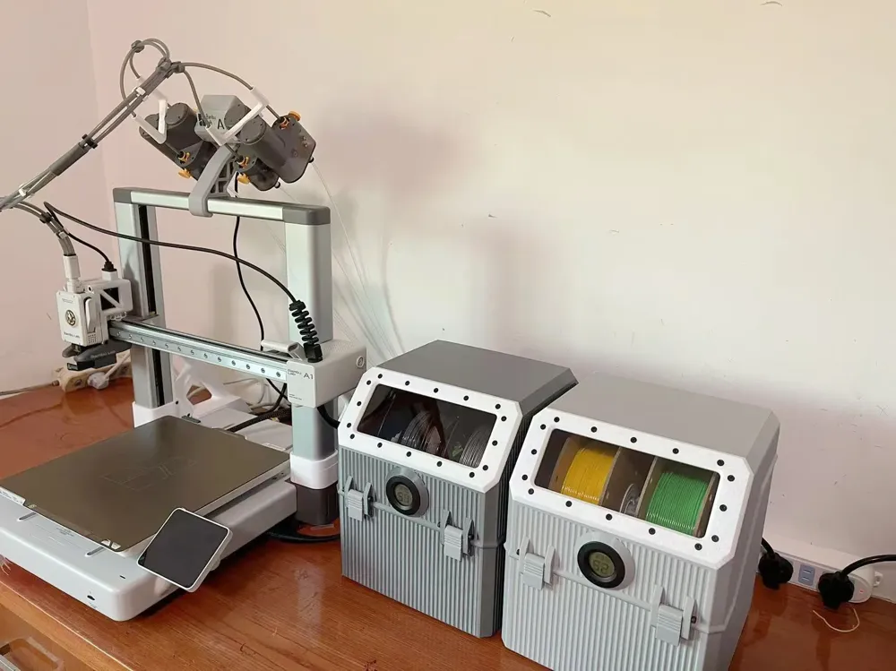
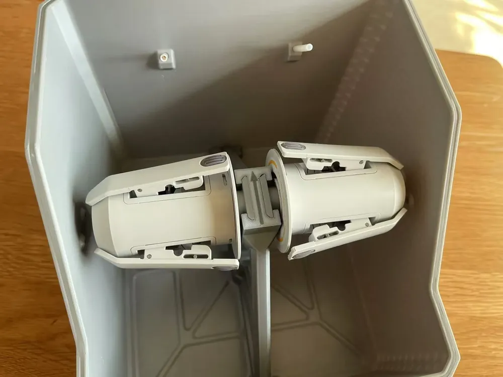
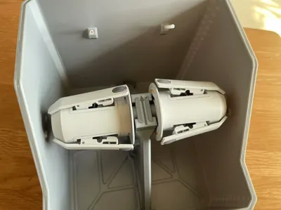
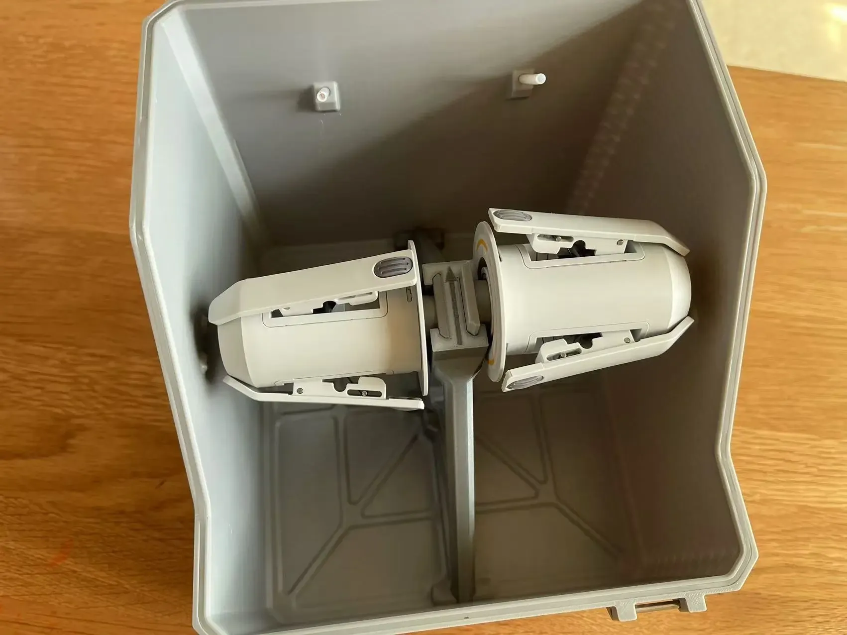
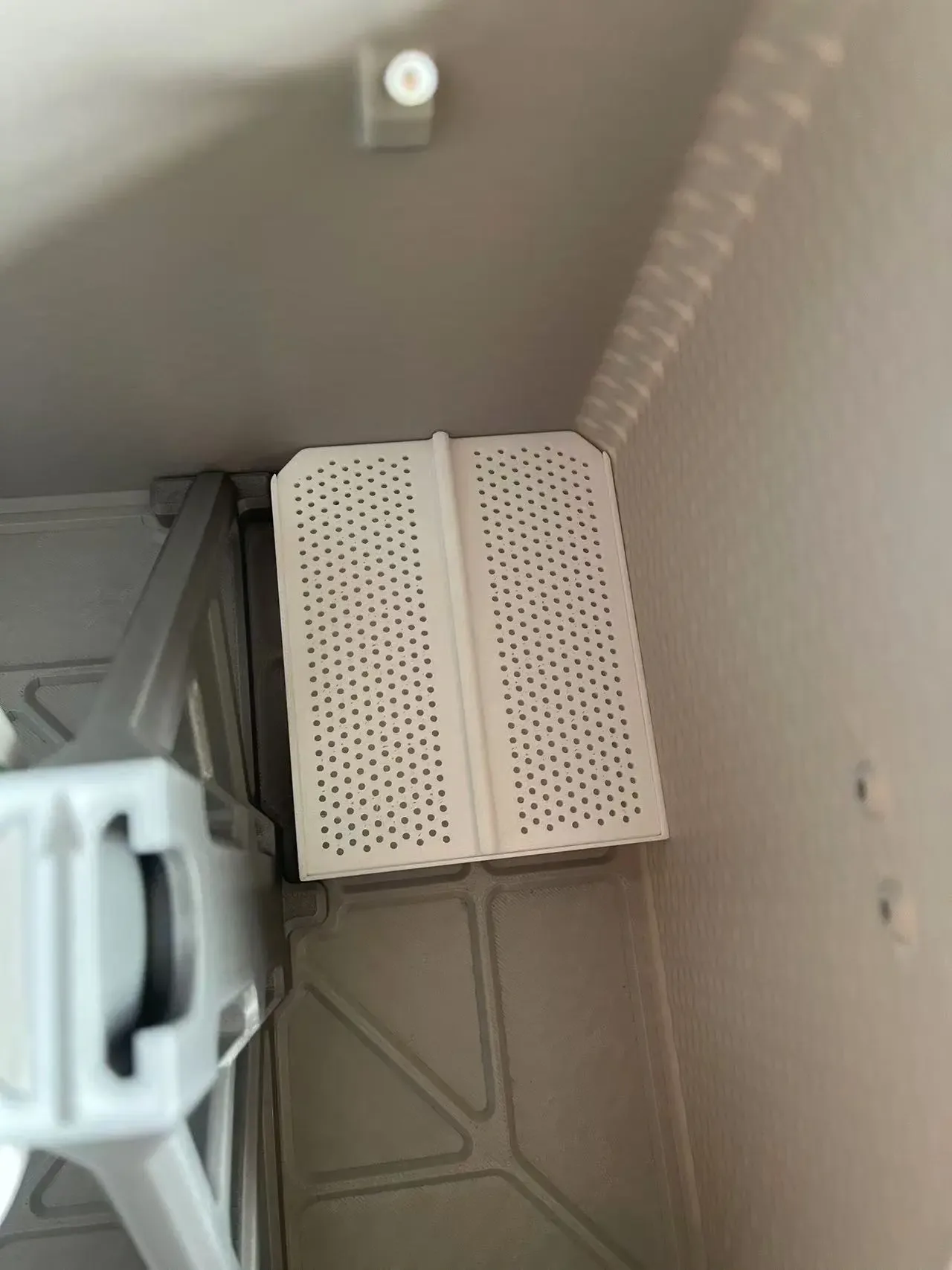
- A single desiccant chamber accommodates two filament spools Two chambers can be stacked or placed side-by-side, depending on your setup One AMS lite requires two chambers, which are also suitable for temporary use with P1 or X1 printers
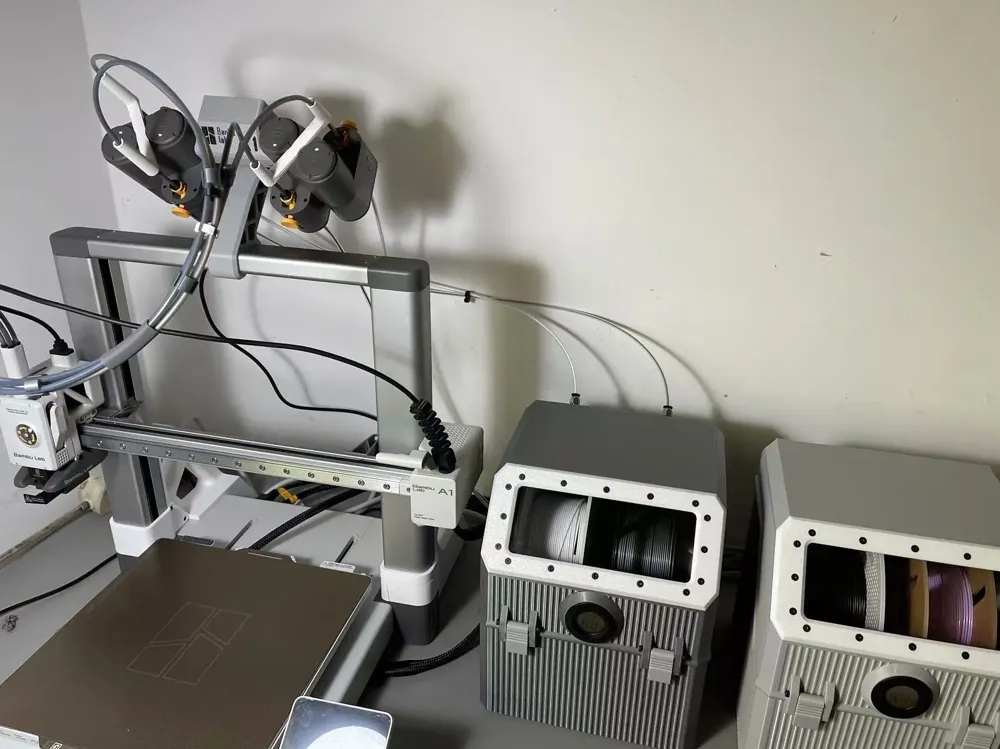
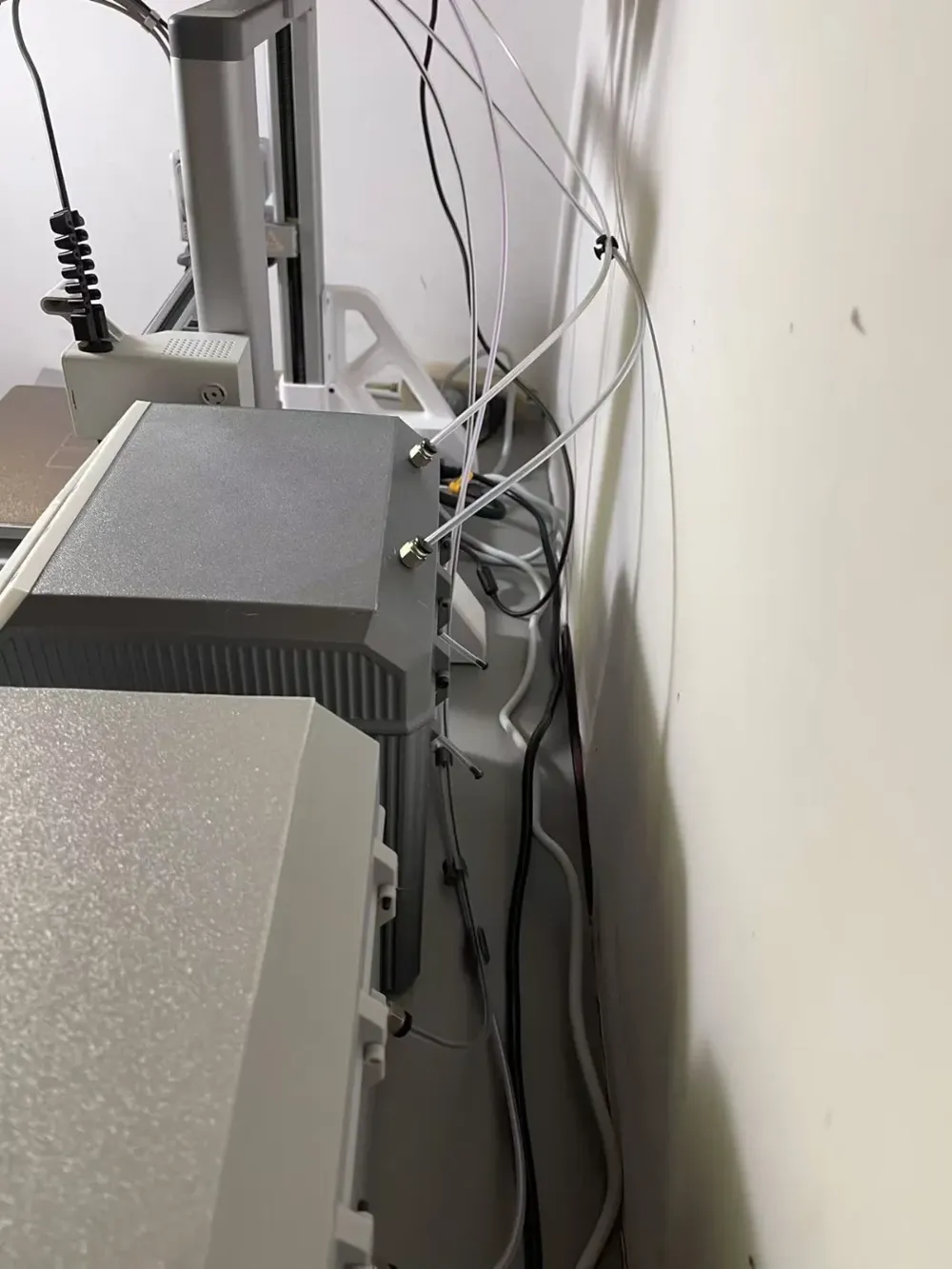
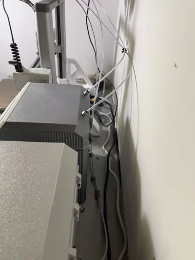
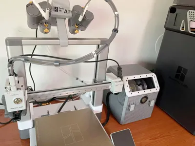
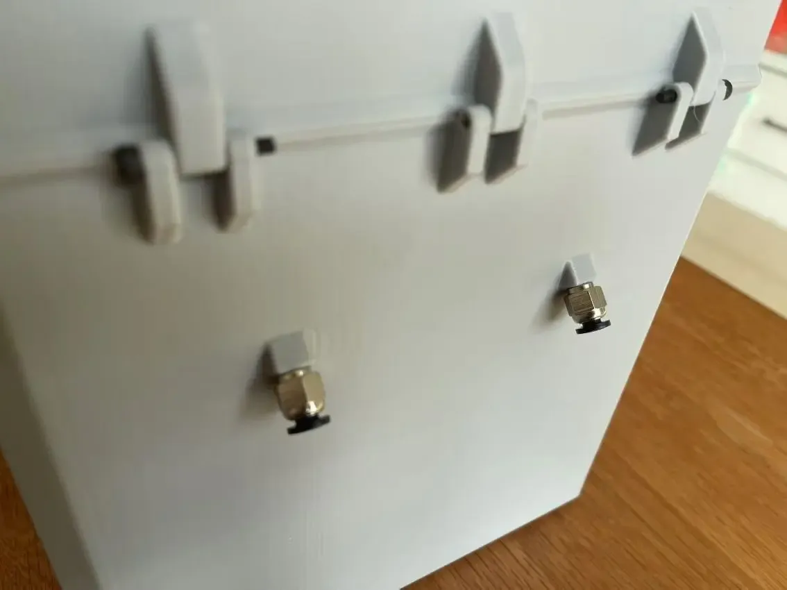
- Reports of high feed resistance are often caused by substandard PTFE tubing with excessive friction Some PTFE tubes, especially transparent ones, exhibit higher friction Opt for 3D printing-specific PTFE tubing I have included several diagrams illustrating PTFE tubing routing for the desiccant chamber to the motor Both the top and bottom outlets function well; the optimal setup depends on your configuration, both have been tested and proven reliable for extended periods See images below for reference
- Improper PTFE tubing routing from the AMS motor to the extruder can also lead to this issue Refer to my diagrams
- For AMS motor and control board installation, refer to my profile for a top-mount motor solution Download and print as needed
- Bill of materials (per desiccant chamber; multiply quantities by 2 if you need two chambers):
- If not modifying an AMS lite, you will also need the AMS lite rotary shaft
- M3X10mm countersunk socket head cap screws, 22 pieces
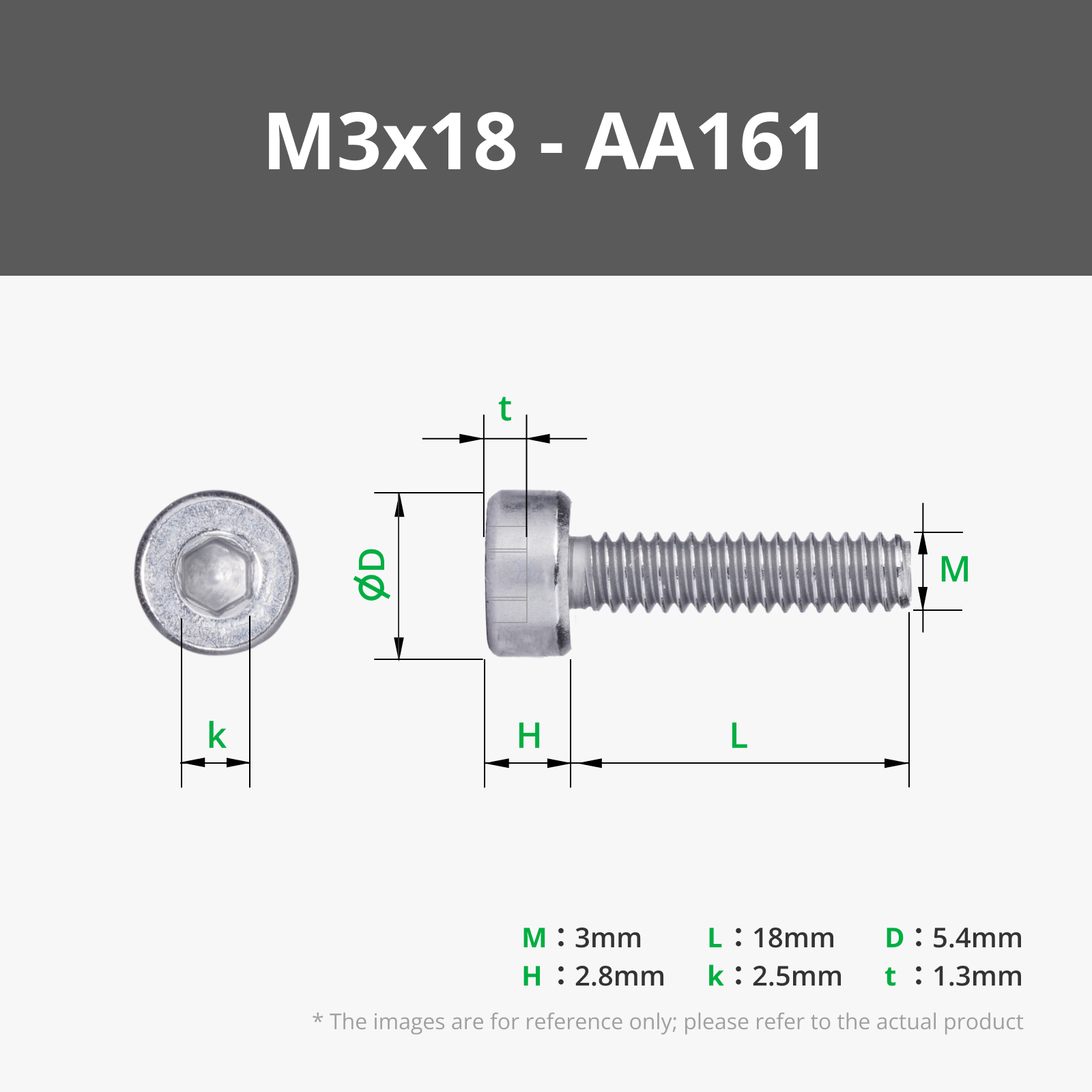
- M3X18mm socket head cap screws, 3 pieces
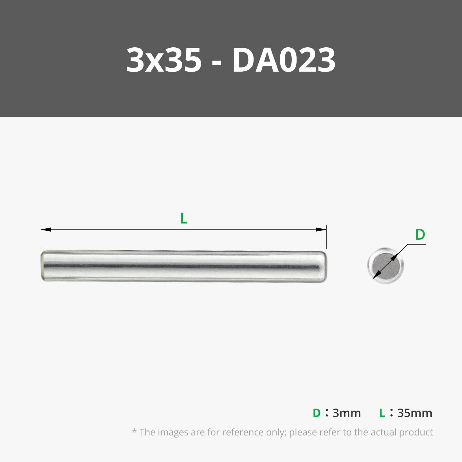
- M3X30~34mm socket head cap screws or 3MM diameter shafts, 4 pieces
- PTFE tubing 4X2.5MM, 4 meters
- PC4-M6 quick connectors, 2 pieces
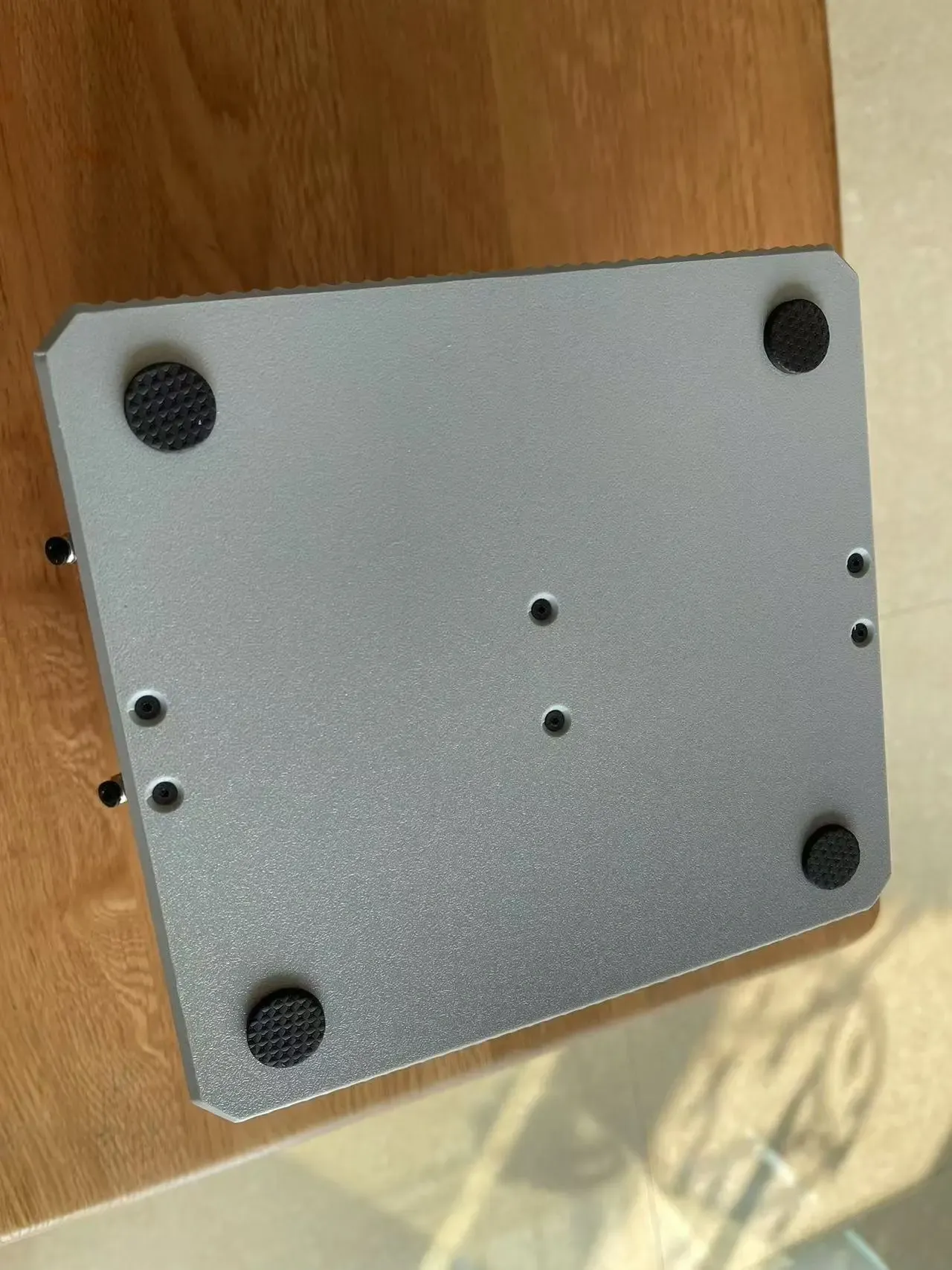
- Circular foam pads 20X3MM, 4 pieces
- Silicone sealing strip 2X2MM, 2 meters
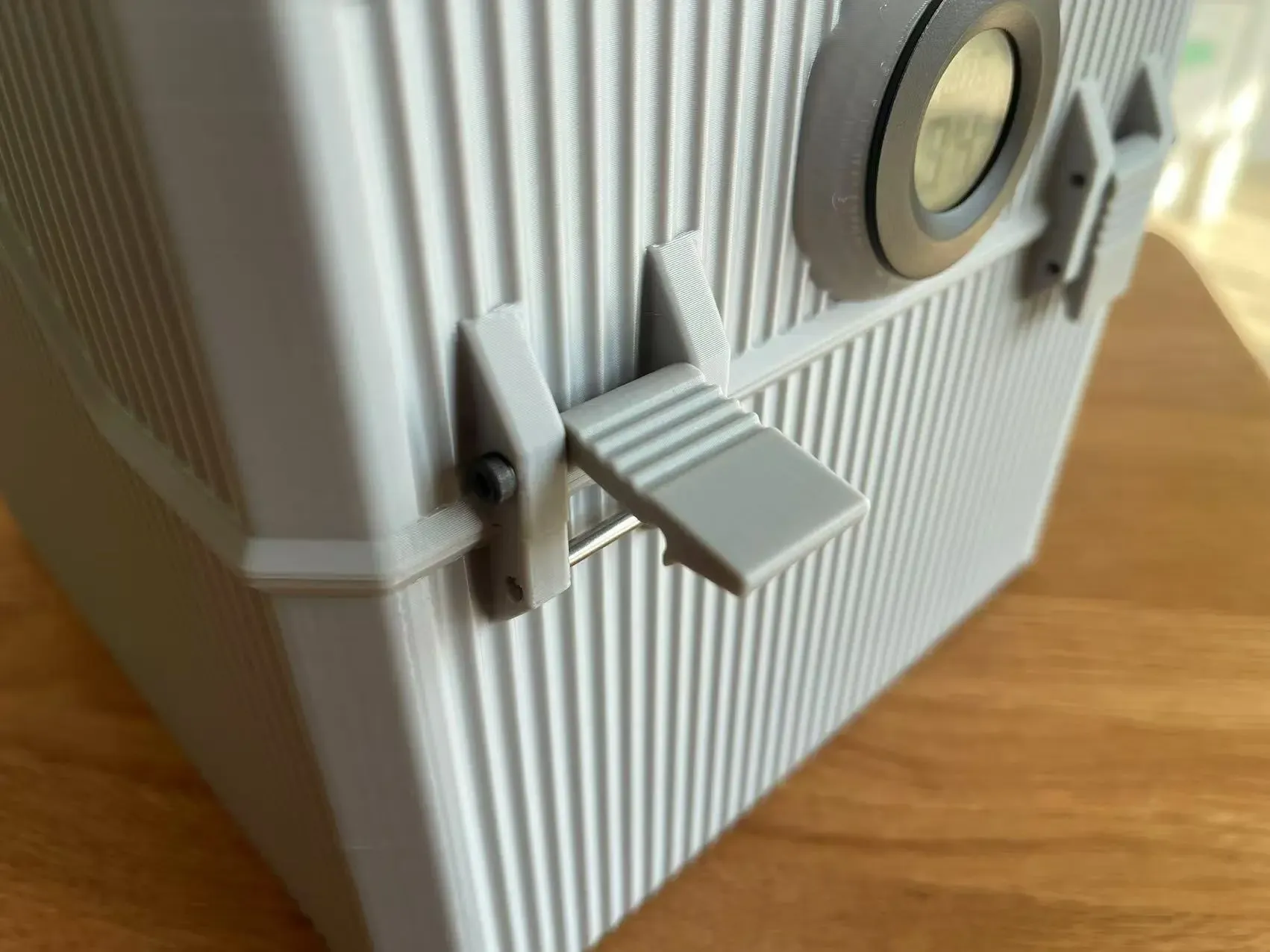
- Circular embedded digital hygrometer, 1 piece
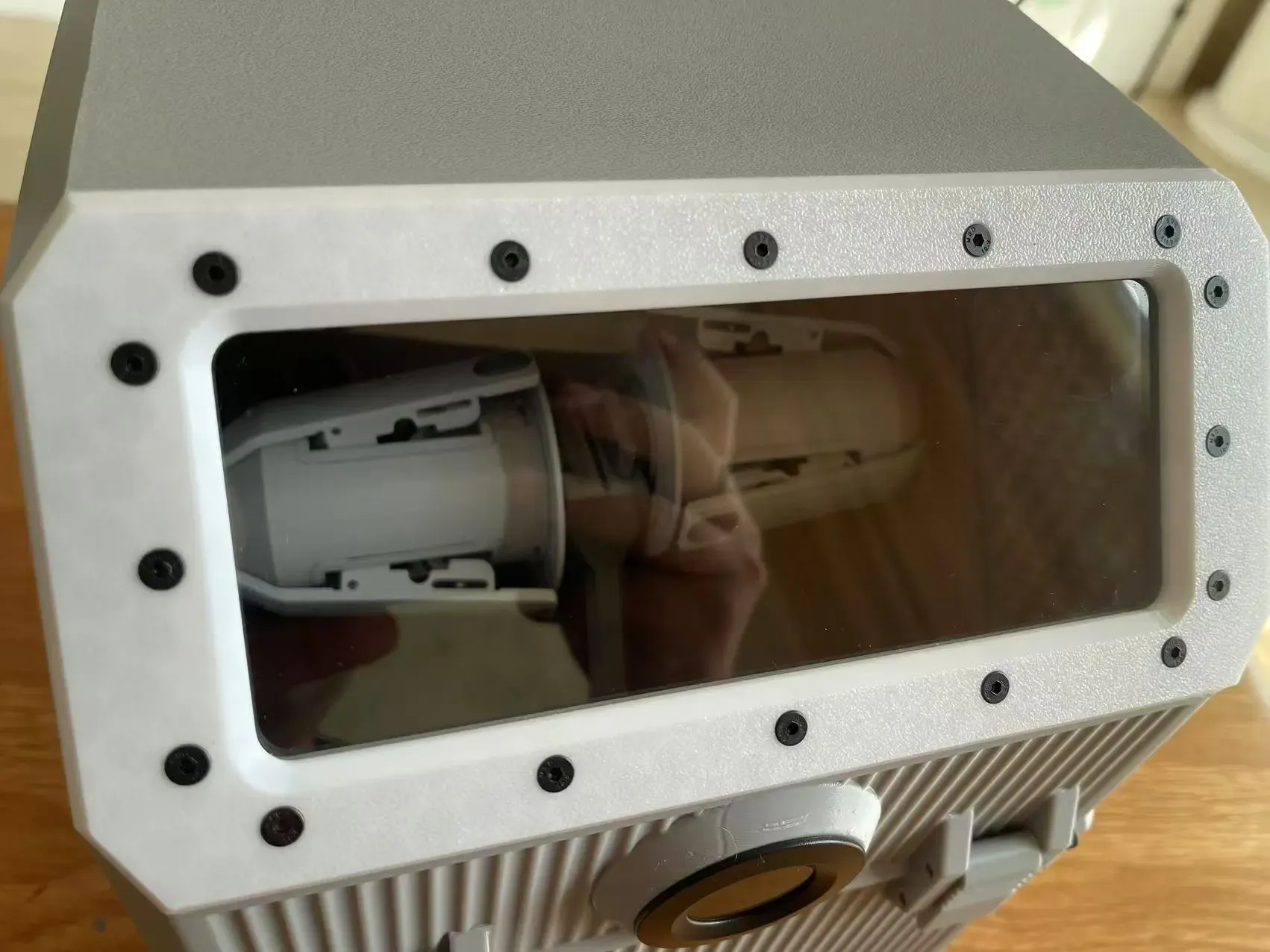
170x70x2mm transparent plastic sheet, 1 piece
Tubing Layout Reference:
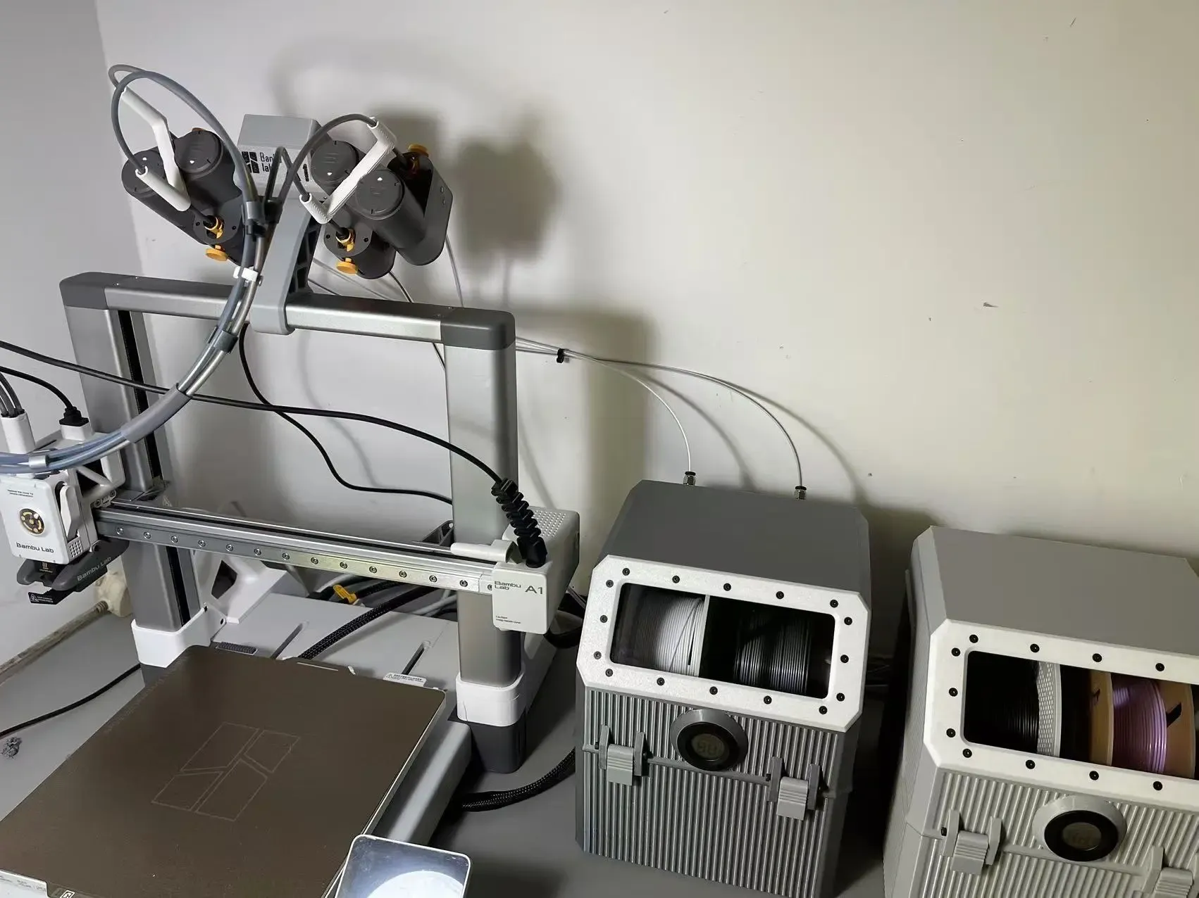
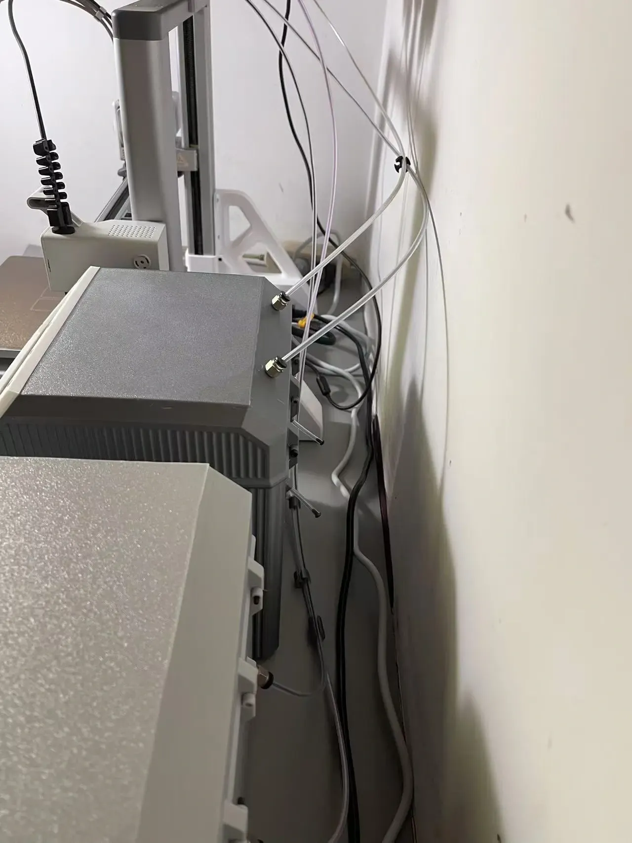
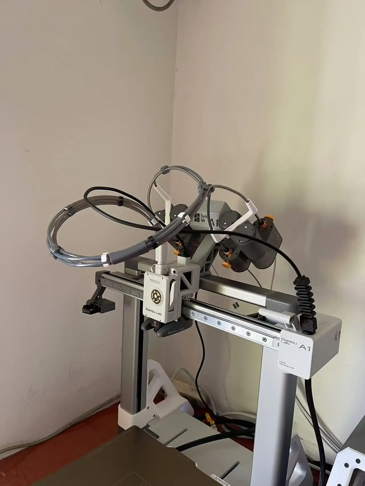
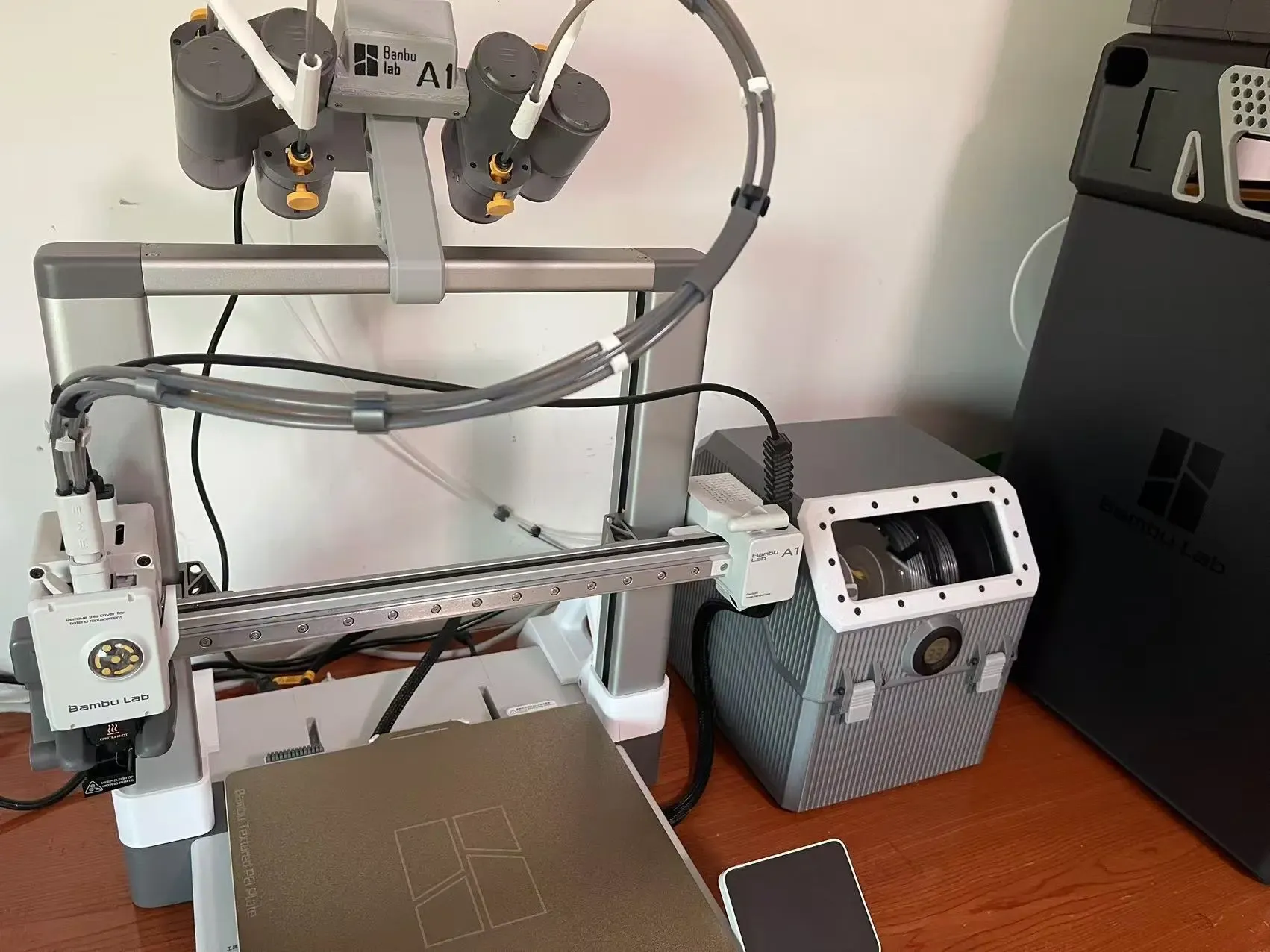
Assembly Reference:
License

You shall not share, sub-license, sell, rent, host, transfer, or distribute in any way the digital or 3D printed versions of this object, nor any other derivative work of this object in its digital or physical format (including - but not limited to - remixes of this object, and hosting on other digital platforms). The objects may not be used without permission in any way whatsoever in which you charge money, or collect fees.


Comment & Rating (134)