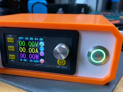
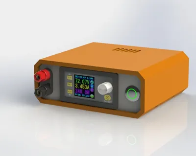
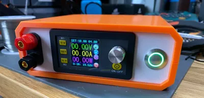
DPS5020/DPS5015 Power Supply Enclosure


Print Profile(1)

Description
Boost Me (for free)
All my files are free and self-funded - boosts help cover filament costs and let me keep giving back to the MakerWorld community.
Thank you for the support! ❤️
This is a functional remix of https://www.thingiverse.com/thing:3091269.
Designed to work with the DPS50XX series of power supplies.
If you land up making one, please do post it here and if you land up remixing it, please share the files with everyone!
Changes:
- Increased footprint for DC-DC converter board for the DPS50XX series
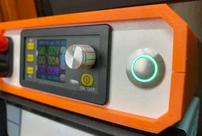
- Added an illuminated power switch to the front panel
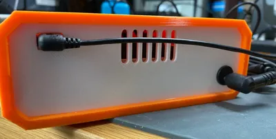
- Added the DPS USB comms module to the rear panel with cutout for a micro usb cable
BOM:
| Component | URL |
|---|---|
| DPS5020 - BT | [https://www.aliexpress.com/item/32821185351.html] |
| Screw Terminals | [https://www.amazon.com/Wiwaplex-Insulated-Terminal-Binding-Amplifier/dp/B01LYA4YDP] |
| Power Switch | [https://www.digikey.com/en/products/detail/e-switch/PVA6LRE21231/7423421 |
| M3 Heat-Set Inserts | [https://www.amazon.com/Insert-Inserts-Compatible-FX-888D-SP40NUS/dp/B08BJD3W4X] |
| M3 x 6mm Screws | [https://www.amazon.com/Alloy-Assortment-Oxidation-Treatment-Pieces/dp/B078V3YCF6] |
| M3 x 12mm screws | [https://www.amazon.com/Alloy-Assortment-Oxidation-Treatment-Pieces/dp/B078V3YCF6] |
| 5.5 x 2.1 MM 1A DC Power Jack Socket | [https://www.amazon.com/Threaded-Connector-Adapter-7-87Ich-Lsgoodcare/dp/B07R6KB6GX] |
| 12 AWG, 14AWG, 30AWG Silicone Wire | [https://www.amazon.com/s?k=silicone+wire&ref=nb_sb_noss_2] |
| Felt Pads | [https://www.amazon.com/Scotch-Value-Round-Assorted-SP845-NA/dp/B00V7UD93C] |
Post-Printing
Step 1
Install 4x M3 heat-set inserts in the standoffs for the power board in the case bottom. Use a soldering iron on moderate temperature (~500F).

Next, install 4x M3 heat-set inserts in the case top. Use a soldering iron on moderate temperature (~500F).

Step 2
Use four M3x6mm bolts and install the power supply module in the case bottom.
Step 3
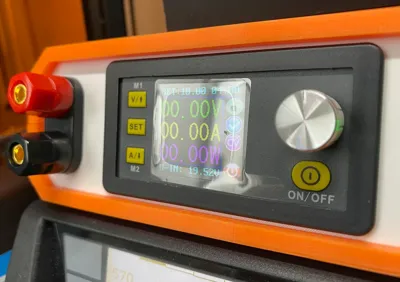
Install the screw terminals, DPS50XX display module and power switch in the front panel.
Step 4
Install the barrel jack socket in the rear panel and install the USB communications module using a pair of M3x6mm screws.

Step 5
Wire the power switch in line between the +ve power terminal of the barrel jack and the input to the DPS50XX power supply module.

Step 6
The 3.3V supply for the power switch LED can be tapped from an existing 3.3V regulator on the power supply module. Yellow wire = 3.3V, Black wire = GND.

Step 7
Complete the rest of the wiring for the screw terminals, LCD, Keypad and USB communications module.


For Under-Desk Dual Power Supply (12V/4A & 5V/8A) see: https://makerworld.com/en/models/2408563-under-desk-dual-power-supply-12v-4a-5v-8a#profileId-2640580
License
You shall not share, sub-license, sell, rent, host, transfer, or distribute in any way the digital or 3D printed versions of this object, nor any other derivative work of this object in its digital or physical format (including - but not limited to - remixes of this object, and hosting on other digital platforms). The objects may not be used without permission in any way whatsoever in which you charge money, or collect fees.
Comment & Rating (5)